1
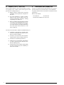
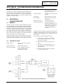
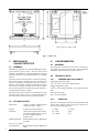
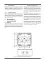
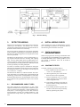
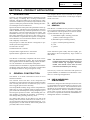
USER MANUAL
Issue: 2
IR S161
Date: 01/94
SECTION A - PRODUCT APPLICATION
1.
INTRODUCTION
The S161 is an infra-red flame detector designed to provide
early warning of flaming fires involving carbonaceous
materials. The detector makes use of “state of the art” infrared sensors and filters to provide major improvements in the
rejection of deceptive phenomena while retaining the inherent advantages of infra-red detectors.
Special attention has been paid to the optimisation of the optical bandwidth. The detector uses optical filters which are
made to THORN Security Limited's specification to restrict
the response to a narrow bond in the region of 4.4mm. The
bandwidth chosen gives high sensitivity to hydrocarbon
fires while minimising the response to other sources of infra-red radiation. In particular the response to sunlight has
been reduced to a level at which the detector can be considered completely “solar-blind”.
The complete detector may be mounted on an optional
stainless bracket which allows a wide range of adjustments in two axes.
3.
APPLICATION
3.1
GENERAL
The detector is intended for the protection of high risk
areas in which accidental fires are likely to result in flaming combustion with the production of carbon dioxide.
Typical materials in this type of risk are:
a) Flammable liquids, including petroleum
products, alcohol and glycol etc.,
b) flammable gases including methane,
The principles on which the detector is designed, are protected by the following patterns:
c) paper, wood and packing materials,
US Patent No. 4471221
e) plastics.
d) coal,
Canadian Patent No. 1191229
European Patent Application No. 823107462
Japanese Patent Application No. 62667/82
The detector is electrically compatible with most conventional 2-wire fire detection systems. The circuit techniques
used, together with the mechanical design, allows the detector to be certified for use in hazardous atmospheres.
The hazardous area classification, together with the mechanical design, allows the detector to be used as a replacement
for flameproof detectors using existing Ex d wiring.
2.
GENERAL CONSTRUCTION
The detector is of robust construction to allow its use in
harsh environments.
The infra-red sensor and other circuit components are
mounted on a single printed circuit board within a stainless
steel screening box. The box is filled with epoxy resin to
form a rugged opto-electronic assembly.
The encapsulated assembly along with an encapsulated interface unit is in turn contained within an impact-resistant
glass reinforced moulded plastic housing designed to give a
level of ingress protection to IP67. The moulding mix contains graphite to eliminate the possibility of generating a
static charge during cleaning with a dry cloth.
These substances ignite readily and burn rapidly, producing flame, often accompanied by large volumes of
dark smoke.
Note: The detectors are not designed to respond
to flames emanating from fuels which do not
contain carbon e.g. hydrogen, ammonia,
metals, and should not be used for such
risks without satisfactory fire testing.
The S161, by virtue of its construction and rejection of
spurious radiation, is suitable for use both indoors or outdoors in a wide range of applications.
3.2
USE IN HAZARDOUS
ATMOSPHERES
The detector design uses the techniques of intrinsic safety, encapsulation and increased safety to achieve a classification of Ex e s ib IIC T5. This classification allows
the detector to be used without a zener safety barrier as a
direct replacement for detectors certified Ex d (flameproof). How- ever the circuit wiring must comply with
Ex d or Ex e requirements and the use of BASEEFA certified glands rated Ex e is mandatory.
Two 20mm cable entries are provided in one side of the
housing and all electrical connections are made to two 4way blocks and an end of line terminal block housing. A cable gland plate, secured inside the metal cable glands (not
provided) enable screen continuity.
1
4.
BENEFITS OF THE S161
Infra-red flame detectors offer certain benefits over detectors working in the visible or ultra-violet regions of the
spectrum. For example they are:
a) Highly sensitive to flame thus increasing
probability of early detection of hydrocarbon fires,
b) not greatly affected by window contamination by dirt and oil deposits thus decreasing maintenance frequency leading
to operating cost reduction,
c) able to see flames through smoke and able
to see flames through high densities of solvent vapours thus increasing the probability of early detection of hydrocarbon fires
over other (ultra-violet) detectors in the
same conditions,
The S161 has all the above benefits and additionally it is:
d) completely “solar-blind” in normal conditions thus eliminating false alarms due to
direct or indirect sunlight,
e) insensitive to electric areas thus eliminating false alarms from welding operations,
f) insensitive to artificial light sources,
g) suitable for use in hazardous atmospheres
as a direct replacement for detectors certified Ex d (flameproof),
h) sealed to IP67 (when suitable cable glands
are used) ensuring long term reliability in
harsh environments.
2
5.
ORDERING INFORMATION
The S161 is supplied without a fitted bracket as in some applications detectors are bolted directly onto a bulkhead.
A separate stainless steel 316 bracket is available for better
applications.
Stock Code Number:
S161 Detector
516-009-022
Stainless Steel Bracket 517-001-184
USER MANUAL
IR S161
Issue:2
Date: 01/94
SECTION B - SYSTEM DESIGN INFORMATION
1.
INTRODUCTION
The design of a system incorporating S161 flame detectors
must take account of the detector's electrical, mechanical
and environmental characteristics, and its detection performance. This information is given below together with
guidance on detector siting.
2.
2.1
ELECTRICAL
CHARACTERISTICS
GENERAL
The S161 is a two-wire device which is designed to operate
on any fire detection control equipment currently manufactured by THORN Security Limited or similar fire detection
controllers. The quiescent current drain is very small and
the alarm condition is latched in the detector and signalled
by a large increase in current demand. Resetting is
achieved by removing the supply voltage for a period of at
least five seconds. An interface unit is located inside the
front cover adjacent to the detector module.
The Interface Unit is advice which limits the power transferred to the detector module to a safe level. The end to
end resistance of the Interface Unit is nominally 373 ohms.
2.2
TECHNICAL DATA
Supply Voltage:
18.0V to 24.0V d.c. (polarity
conscious)
Quiescent Current:
100mA max at 20V d.c.
Alarm Output Mode:
2-wire, latching 720 ohm in
series with typically 4V
switched across supply.
Fig. 1
In-rush Current:
800mA peak decreasing with
a time constant of 250ms to
the quiescent current.
Alarm Indication:
red LED visible from front of
detector.
Reset Time:
Not greater than 1 second.
Reset Voltage:
Supply must be reduced to
less than 2V.
Stabilisation Time:
20 seconds (typical)
End of Line Resistors:
0.6 Watt minimum, 2k4
minimum metal film 5% not
smaller than 2.5mm diameter
and 10mm long, actual
resistor value dependent on
controller.
Detectors from serial number 16000 onwards have been
modified to facilitate their use with control panels not
manufactured by THORN Security Limited, where the
reset is short.
The reset facility is implemented as follows:
a) For fast reset to operate it is necessary
for the supply to be removed for a minimum of 0.5 seconds,
b) the supply must fall by greater than 5
Volts,
c) the detector [or Zone] must have an
end-of-line resistor with a resistance of
less than 100k,
d) the noise immunity on the line [ripple]
is less than 3 Volts peak.
S161 Connection and Internal Wiring Including EOL
3
Fig. 2
3.
3.1
S161 Cover
MECHANICAL
CHARACTERISTICS
4.
GENERAL
The design and construction of the S161 is such that it
may safely be used over a wide range of environmental
conditions. Relevant limits are given in para. 4.2.
The detector comprises a two-part moulded plastic enclosure as shown in Figs. 2 and 3. The rear section of the
housing is attached to an optional adjustable mounting
bracket or the detector may be fitted directly to a suitable
surface.
4.1
4.2
ENVIRONMENTAL
GENERAL
TECHNICAL DATA
The front section of the enclosure contains the encapsulated electro-optical assembly and the interface unit
which is connected to the terminal blocks by a small cableform. Two sapphire windows are fitted in the front of
the housing. The upper window allows infra-red radiation to fall on the sensor and the LED alarm indicator is
visible through the lower window.
4.2.1
The front section of the enclosure is attached to the rear
section by four captive screws. A seal provided between
the front and rear sections ensures protection to IP67.
Enclosure Protection:
IP67 - IEC529, BS5490
Operating temperature range:
-20oC to +80oC (-40oC with reduced range)
Storage temperature range:
-40oC to +80oC Relative humidity: 95% (100% intermittent)
4.2.2
3.2
TECHNICAL DATA
VIBRATION
The S161 is designed to operate within specification and
without false operation when subjected to vibration on
any axis at the following levels:
Dimensions:
160mm x 160mm x 90mm without
bracket (see Figs. 4 and 5).
Weight:
2.0kg (with optional bracket)
2 - 24Hz
+1.27mm
Enclosure:
Glass reinforced polyester with an
anti-static graphite content, interior
& exterior metal fittings of
stainless steel.
24 - 55Hz
2.50g
55 - 100Hz
0.7g
Mounting Bracket:
Bright Stainless steel to BS1449 Pt
2 316S16.
Screws, etc. exposed
to the elements:
Bright Stainless Steel to BS970 Pt1
316L.
4
TEMPERATURE AND HUMIDITY
4.2.3
5.1.1
RADIO FREQUENCY
INTERFERENCE
The detector is insensitive to radio frequency interference
and will operate normally in field strengths of 10V/m at frequencies up to 1000MHz. It thus meets or exceeds the requirements of BS6667: Part 3 1985 (IEC 801-3: 1984)
severity level 3 (severe electromagnetic environments).
4.2.4
IONISING RADIATION
The S161, like other infra-red detectors, is insensitive to Xrays and gamma radiation as used in non-destructive
testing. The detector will operate normally and will not
false alarm when exposed to this type of radiation although
long term exposure to high radiation levels will ultimately
lead to permanent damage.
5.
5.1
PERFORMANCE
CHARACTERISTICS
GENERAL
A large number of fire tests have been carried out to determine the response limits of the S161 detector. The results of
these tests are summarised below. In order to appreciate
their significance, an understanding of the mode of the operation of the detector is necessary, and a brief explanation follows:
Fig. 3
MODE OF OPERATION
BEHAVIOUR IN FIRE TESTS
Flaming fires involving carbonaceous materials produce
large quantities of carbon dioxide. This part of the combustion process gives rise to a very high level of infrared radiation in the wavelength region between 4.2µm
and 4.7µm. The unique patented filtering system of the
S161 Detector restricts the radiation reaching the sensing cell to a narrow band of infra-red radiation in the region of 4.4µm.
The radiation from a fire flickers in a characteristic way
and the detector uses this flicker signal to give extra discrimination against interfering infra-red sources.
The detector circuit analyses the signal within the flicker
frequency region and, if the amplitude of the signal is
above a preset threshold level for three seconds, then an
alarm is signalled. If the signal is below this threshold
level then the detector will not alarm even after a long
period of time.
The level of the signal depends upon the size of the flame
and its distance from the detector. For liquid fuels the
level is roughly proportional to the surface area of the
burning liquid. For any type of fire the signal level varies inversely with the square of the distance.
S161 Housing Showing Fixing Dimensions
5
For convenience, fire tests are normally carried out using
liquid fuels burning in pans of known area in still air. The
sensitivity of a detector can then be conveniently expressed as the distance at which a particular fire size can
be detected.
It is important to think in terms of distance rather than time
because of the different burning characteristics of different
fuels. Fig. 5 shows the response to two different fuels
which ultimately produce the same signal level.
Fig. 4
Mounting Bracket
Fig. 5
6
The signal level given by petrol quickly reaches its maximum, and produces an alarm within about six seconds of
ignition. Kerosene, on the other hand, being less volatile,
takes about a minute to reach equilibrium and an alarm is
given in about 55 seconds from ignition. The time taken by
the fire to reach equilibrium depends of course on the initial temperature of the fuel. If the Kerosene were to be preheated to a temperature above its flash point then its behaviour would be equivalent to that of petrol at 25oC. The test
data presented below refers to fires which have reached
their equilibrium condition.
Stockcode 517-001-184
Response to Fires
Fig. 6
5.2
Detection Ranges vs Pan Area - Petrol
5.3
FIRE TEST DATA
5.2.1
PETROL
The most convenient fuel for fire tests is petrol (gasoline)
since it is readily available and quickly reaches its equilibrium burning rate.
The graph in Fig. 6 shows the detection range as a function
of pan area for petrol fires. It will be seen that this curve is
approximately a square law that is to say that to obtain detection at twice the distance the pan area must be multiplied
by four.
The sensitivity of the detector is constant over the voltage range +18.0V to +24.0V d.c. The performance outside this range is not guaranteed.
5.4
OTHER LIQUID HYDROCARBONS
Ranges achieved with other fuels burning on 0.1m2 pans are
as follows:
TEMPERATURE DEPENDENCE
The range of the detector will vary by less than +10%
over the range of -20oC to +70oC.
5.5
5.2.2
VOLTAGE DEPENDENCE
DIRECTIONAL SENSITIVITY
The sensitivity of the S161 is at a maximum on the detector axis. The variation of range with angle of incidence is shown in Fig. 7.
n-heptane
18m
Kerosene
18m
6.
DESIGN OF SYSTEM
Alcohol (I.M.S.)
15m
6.1
GENERAL
Diesel oil
15m
Ethylene glycol
18m
Using the information given in paras. 2 to 5 it is possible
to design a flame detection system having a predictable
performance. Guidance on the application of the above
data and on siting of detectors of given below.
The detection range for other pan areas may be calculated
using the square law relationship given in para 5.2.1.
5.2.3
GAS FLAMES
Most flammable gases contain carbon, and the radiation produced when such gases burn is easily detected by the
S161. Additionally, tests have shown that “accidental” fires
involving gases will produce sufficient flicker to give rapid
alarm response from the detectors. This is equally true for
fires resulting from low pressure [(less than 0.5 lb/in2 (0.035
kg/cm2))] leaks.
Typical results obtained by burning natural gas (methane)
from a 1 inch (25.4mm) diameter pipe are given below:
GAS PRESSURE
(lb/in2) (kg/cm2)
DETECTION RANGE
(metres)
0.5
0.035
30
1.0
0.070
30
5.0
0.351
50
25.0
1.758
60
6.2
USE OF FIRE TEST DATA
It has been explained in Para 5 that the sensitivity of the
detector is most easily specified in terms of its response
to well-defined test fires. Tests are conveniently carried
out using a 0.1m2 pan. Sensitivity to other pan areas is
calculated from the square law relationship.
Accidental fires by their very nature rarely of a well-defined size. It is still possible however to judge the response to a p fire using the fire test data.
For a example. A spillage fire involving a highly volatile
liquid such as petrol will spread very quickly from the
point of ignition to cover the complete surface of the
pool. Such a spillage would normally cover 2m2 or so.
Using the data for petrol fires and extrapolating to an
area of 2m2 we would expect the S161 to respond within
10 seconds at a distance of about 80 metres. At a distance
of 20 metres the response time would only be a few seconds less and in any event can never be less than 3 seconds.
7
c) the S161 may be used to look vertically
downwards on to a risk area since smoke
blocking is minimal,
If on the other hand the spillage involved a less volatile
material such as kerosene, the spread of flame from the ignition point would be much slower. The detector would
then respond in a time independent on the distance from
the fire. At 18 metres, for example, an alarm would be
given when the fire had reached 0.1m2 and at 36 metres,
when the fire had grown to 0.4m2.
6.3
DETERMINING NUMBER OF
DETECTORS
It will be clear that the number of detectors required for a
particular risk will depend on the area involved and the fire
size at which detection is required. Large areas or small
fires require large numbers of detectors.
There are as yet no agreed “rules” for the application of
flame detectors and the overall system sensitivity must
therefore be agreed between the installer and the end
user. Once this agreement has been reached the system
designer can determine the area covered by each detector
using a scaled plot based on Fig. 7 and the fire test
data. This plot is best drawn to the same scale as the site
plan so that direct imposition can be used to determine detector coverage.
In carrying out the design, certain factors should be kept
in mind:
a) For area rather than spot protection, the
best coverage will normally be obtained
mounting the detectors on the perimeter of
the area and pointing into the area,
b) as the S161 is a line of sight detector any
object within the detector's field of view
will cause a “shadow” in the protected
area. Even small objects close to the detector can cause large shadows
Fig. 7
8
d) the detectors are passive devices and will
not react with one another. They may
therefore be positioned with their fields of
view overlapping.
7.
APPROVALS AND
COMPLIANCE WITH
STANDARDS
7.1
SAFETY
The S161 has been certified by BASEEFA for use in hazardous atmospheres under certificate number Ex
87Y3550. It is classified: Ex e s ib IIC T5, indicating a primary means of protection of Ex “e” (increased safety). It
is therefore suitable for use in zone 1 or zone 2 areas if installed to the requirements of BS5345 : Parts 6 and 8.
7.2
OTHER STANDARDS
The S161 is a development from S111 offering a more robust housing. The S111 has been submitted to independent tests which show that it meets all the requirements of
the “C.E.A. Test Methods for Point Infra-red Flame Detectors” up to its designed angle of vision of 90o.
7.3
OTHER APPROVALS
The complete list of approvals for ALL equipment is given
in THORN Publication 05A-01-G1 which is updated at
regular intervals.
Relative Range vs Angle of Incidence
USER MANUAL
Issue: 2
IR S161
Date: 01/94
SECTION C - INSTALLATION
1.
GENERAL
The S161 detector is supplied with the option of an adjustable mounting brackets for fixing to a convenient rigid
surface. All electrical connections are made via the two
4-way terminal blocks and an end of line terminal block
inside the detector housing. Two 20mm cable entries are
provided. Guidance on mounting and wiring the detectors
is given below. A cable gland plate, secured inside the
housing by metal Ex d (flameproof) cable glands, provides
screen continuity.
2.
MOUNTING A DETECTOR
The location of each detector should have been determined at the system design stage according to the principles detailed in Section B marked on the site plan.
The detector may be mounted on a horizontal or vertical
surface. The actual mounting position must, however, be
decided during installation, and in choosing the position
the principles following together with the original system
requirements should be followed.
Fig. 1
2.2
2.1
CHOICE OF MOUNTING POSITION
The following points must be observed when choosing the
mounting position.
a) The detector must be positioned such that
a clear line of sight is provided to all parts
of the risk area. Roof trusses, pipework,
supporting columns etc. in front of the detector can cause significant shadowing and
should be avoided,
b) if supervision of an area immediately below the detector is required it is essential
that the angle between the detector and the
horizontal is not less than 40o,
Detector Fixing Dimensions
MOUNTING BRACKET
The detector mounting bracket is to be secured with two
M8 bolts, studs or screws at the fixing centres shown in
Fig. 1. A drilling template is provided to allow the optimum selection of the fixing centres and the 2.5mm diameter, 3mm deep pivot hole.
The surface chosen for the mounting should be flat over
the area of the bracket or detector to ensure a stable fixing.
The S161 may be operated in any position but the actual
mounting point must obviously be chosen to allow sufficient clearance for adjustment of the angle and must also
allow space for the cable assembly. A clearance of
200mm, in all directions, from the fixing point will normally be sufficient to allow the full range of
adjustment. Fig. 2 refers.
c) the detector should not be sited in a position where it will be continually subjected
to water drenching,
d) in outdoor installations in areas of high solar radiation, some form of sunshade is
recommended to prevent excess heating of
the detector,
e) the detector should not be sited in a position in which it will be subject to severe icing,
f) the detector must be mounted on a stable
structure which is readily and safely accessible for maintenance staff.
The detector may be secured directly to the fixing surface
with two or more M6 bolts, studs or screws at the fixing
centres shown in Fig. 1.
Fig. 2
Clearance Required for Full Adjustment
9
Fig. 3
3.
Detector Wiring
DETECTOR WIRING
Detectors will normally be connected in zones which may
contain up to ten detectors. All detectors on a zone are
connected in parallel and some form of end-of-line device
should be used to monitor line continuity.
The wiring between the detectors and control equipment
must provide the required degree of mechanical protection
but allow the detector alignment to be adjusted to suit the
area to be protected.
The detector is fitted with two 4-way terminal blocks giving separate terminal blocks for incoming and outgoing
lines. The two 20mm cable entries provided permit convenient connection of the incoming and outgoing lines using metal flameproof cable glands with continuity of cable
screens provided by the cable gland plate.
To ensure no moisture ingress to the detector during the
time between Installation and Commissioning tighten the
four hexagonal socket cover retaining screws to torque of
3.5-4.5N.m (2.6 - 3.3lbf.ft).
The End-of-Line Resistor (0.6 Watt minimum. 2k4 minimum. metal film 5% not smaller than 2.5mm diameter and
10mm long, actual resistor value dependent on controller)
should be fitted at the EOL Terminal Block of the last detector situated in the right hand side of the cover as shown
in Fig. 3.
3.1
RECOMMENDED CABLE TYPES
The cable selected for interconnection to the control
equipment should meet the requirements of BS5345: parts
1 & 6 or relevant approval bodies. Cables should not normally have a cross sectional area of less than 1mm2 for
solid conductors or 0.5mm2 for stranded conductors. The
terminal block accepts cables up to 4mm2 cross sectional
area.
10
4.
INITIAL WIRING CHECK
After installing the wiring as detailed above, and before connecting any detectors or end-of-line devices,
the following tests should be carried out.
4.1
TESTS ON WIRING IN
HAZARDOUS AREAS
When carrying out tests on wiring in hazardous areas
it is essential than an INTRINSICALLY SAFE INSULATION TESTER is used. Further guidance on testing systems in hazardous areas can be found in
BS5345: Part 1.
4.2
CONTINUITY TESTS
To check continuity proceed as follows:
a) Short together the bare tails of the + to
+ and - to - at each detector,
b) short together the pair at the end furthest from the control equipment,
c) using an ohmmeter set to its lowest
range, check the loop resistance at the
control equipment end,
d) if the reading obtained is less than 50
ohms record the reading obtained and
proceed to para 4.3,
e) if the reading obtained is greater than
50 ohms locate and rectify continuity
faults by quartering the system.
4.3
INSULATION TESTS
To check the insulation proceed as follows:
a) Using an ohmmeter set to its highest range,
check the resistance between the circuit and
earth,
b) if the reading obtained is greater than 1 megohm, record the reading and proceed to c),
otherwise locate and rectify the earth fault,
c) remove the short-circuit at the end furthest
from the control equipment,
d) measure the resistance between the zone
conductors,
e) if the reading obtained is greater than 1 megohm, record the reading, otherwise locate
and rectify the insulation fault,
f) replace the cover.
11
USER MANUAL
Issue: 2
IR S161
Date: 01/94
SECTION D - COMMISSIONING
1.
e) at this stage the angle of the detector should
be adjusted to view the required area and
the fixing nuts and bolts finally
tightened. The cable from the circuit to the
detector should then be routed, using cable
ties or clips as necessary, to minimise the
risk of physical damage,
SYSTEM CHECKS
Before connecting the zone wiring to the control equipment or to the detectors, a general inspection of the system
should be carried out. In particular the positions of the detectors should be checked to ensure that the requirements
given in the System Design and Installation sections are
met.
2.
CONNECTING AND
COMMISSIONING THE
DETECTORS
2.1
TESTS ON WIRING IN
HAZARDOUS AREAS
When carrying out tests on wiring in hazardous areas it is
essential than an INTRINSICALLY SAFE INSULATION
TESTER is used. Further guidance on testing systems in
hazardous areas can be found in BS5345: Part 1.
f) commission the controller as necessary.
2.3
DETECTOR TESTING HAZARDOUS AREAS
The use of naked flames for detector testing in hazardous
areas is obviously unacceptable. The T110 Test Source
has been designed specifically for the on-site testing of the
S100 Series on infra-red flame detectors in hazardous areas.
When testing the S161, the correct adaptor plate must be
fitted to the T110 Test Source.
S161 Adaptor Plate
2.2
COMMISSIONING PROCEDURE
WARNING:
ENSURE THE SUPPLY TO THE
DETECTOR IS ISOLATED
BEFORE OPENING THE COVER.
Stock Code No: 592-001-005
Note: The T110 has a charge/discharge circuit
which take several seconds to recharge.
Consequently, the T110 does not test the response time of a detector but only tests for response to a flame.
The T110 tests the S161 with a defined energy at a opened
distance, indicating reliably when the S161 is operating
above 75% of its specified performance levels.
Carry out the following procedure:
a) Repeat the HV and LV insulation and continuity tests carried out by the installation
engineer. Record the results obtained,
b) connect the loop wiring at each detector
terminal block,
c) check the correct value EOL resistor is fitted at the EOL terminal block in the last
detector,
d) fit the front cover assembly to the rear section. care should be taken to ensure that
the internal wiring is not trapped between
the terminal blocks and the front
assembly. It should be noted that a rubber
seal is provided between the front and rear
sections of the housing and this seal must
be clean and dry before assembly. It is
also important to ensure that no moisture
is trapped inside the housing. Tighten the
four hexagonal socket retaining screws to
a torque of 3.5 - 4.5 N.m (2.6 - 3.3lbf.ft),
12
USER MANUAL
Issue: 2
IR S161
Date: 01/94
SECTION E - MAINTENANCE
1.
GENERAL
The S161 detector contains encapsulated electronic assemblies. There are no replaceable or adjustable components
within the housing, which should not be opened once installed and commissioned.
Routine maintenance is therefore limited to cleaning and
testing the detectors.
1.1
ROUTINE INSPECTION
At regular intervals of not more than 3 months, detectors
should be visually inspected to confirm that no physical
damage has occurred and that the alignment of the detectors
has not been disturbed. The detector windows should be
checked to confirm that they are not blocked and that no
physical obstructions have been placed between the detector
and the protected area.
1.2
DETECTOR CLEANING
The S161 Infra-red detector is relatively tolerant of accumulations of dirt on the sensor window. However, thick
deposits of dirt and oil will cause a loss of sensitivity.
It is recommended that detectors be cleaned using water
or a detergent solution. A stiff bristle (not wire) brush
may be sued to remove heavy deposits.
Note: The act of cleaning or polishing the detector
face and window may cause a detector to
produce an alarm, it is important, therefore
that before the window is cleaned, the detector should be isolated. By isolating the
relevant circuit at the control unit. The circuit must be de-isolated as soon as cleaning is complete.
In addition, at intervals of not more than 1 year, each detector should be checked for correct operation. Any excessive
deposits of dirt, oil etc. should be removed from the detector
housing as described in 1.2.
Note: The inspection frequency specified above
should be considered as a minimum requirement to be applied in the average
environment. The inspection frequency should
be increased for dirtier environments or those
which present a higher risk of physical damage.
13