1
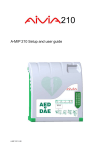
210 A-MIP 210 Installation and user guide General Information Important • The fixations must be adapted to the type of surface on which the AIVIA is fixed. Read this manual before installation and use of the Aivia. Read this section carefully and follow the instructions. The warranty does not cover damage caused by failure to follow these instructions. • The manufacturer cannot be held liable for improper installation or in the case of accident or injury during its installation. Warranty AIVIA PROTECTION are wall mounted protection units that serve to house and shelter AEDs. The AIVIA PROTECTION does not ensure control of the AED, it is the sole responsibility of the DISTRIBUTOR to inform their own SUB-DISTRIBUTORS and USERS of their obligation to verify the presence and operating status of the AED by carrying out regular on site checkups. Depending on the options chosen, the AIVIA PROTECTION can trigger a visual and sound alarm. The alarm is intended as a warning signal in case of any malfunction, but no data log of malfunctions is recorded. In no event can the presence and operating status of AEDs in an AIVIA PROTECTION be controlled from a distance. The AIVIA should in no case be a substitute for the checks and inspections recommended by the manufacturer of the defibrillator. Environmental information Installation must be carried out by a qualified operator or authorized by the Aivia’s manufacturer • When returning the AIVIA, you should only use the original packaging. Never install an AIVIA in direct exposure to sunlight. The unheated AIVIA must be installed in a temperate environment, in accordance with the manufacturer’s specifications for the defibrillator. The heated AIVIA must be installed in an environment that respects the operating temperatures of the AIVIA. You must monitor and follow up alerts related to temperature. • Do not dispose of the AIVIA or its packaging with normal household waste. Use the collection system in place in your area. The use of collection systems will help preserve the environment and your health. The characteristics of the AIVIA are subject to changes without notice. Do not disassemble the various elements that constitute the AIVIA. Do not insert any objects into any openings. Only qualified personnel may carry out repairs on the AIVIA. Failure to comply with this will void any warranty. Any operation or assembly procedures expressly prohibited or not recommended by this manual, will also void the warranty. •The AIVIA can contain batteries in compliance with EU Directives 2006/66/CE and 2008/103/CE. These cannot be disposed of with normal household waste. Please use the system for collecting used batteries in place in your area. The proper disposal of used batteries preserves the environment and your health. The manufacturer of the AIVIA reserves the right to change products at any time, including unlimited modifications to previously delivered products. The AIVIA brand is a registered trademark. Safety • To avoid risk of fire or electric shock, the AIVIA should not be exposed to any naked flame. • Leave a space of at least 13 cm around the AIVIA to assure proper ventilation. • Keep the AIVIA away from radiators or any other heat source. Do not place the AIVIA near any devices that generate heat. Do not place anything under the AIVIA. Maintenance CAUTION THE AIVIA CONTAINS BATTERIES. THERE IS A RISK OF EXPLOSION IF THE BATTERIES SUPPLIED FOR USE BY THE AIVIA ARE REPLACED BY INCORRECT BATTERIES. ONLY AN AUTHORIZED OPERATOR CAN CARRY OUT MAINTENANCE OPERATIONS, INCLUDING REPLACING THE BATTERIES. • To avoid damage, do not insert objects into any of the openings in the AIVIA. • Never install the AIVIA in direct exposure to sunlight. • Do not expose the AIVIA to any moisture when the door is open. 2 Summary Installation Important Aivia presentation Identification plate Initial opening Aivia installation Connecting the power supply to the Aivia Installing the AED Setting up the Aivia Door opening codes Alert temperatures Heating/Fan activation temperatures Close the AIVIA door Pictograms 4 4 4 4 5 6 7 7 7 7 8 8 8 Use 10 Night mode operation Heating option operation Alert operation Using the Aivia After using the defibrillator Aivia maintenance 10 10 10 10 10 10 In case of malfunction 11 Electrical Installation 13 Specifications Mechanical characteristics Technical characteristics Compliance 14 14 14 3 Installation Important Read this manual with carefully before setting up and using the Aivia. 10 Never install Aivia Aivia in direct exposure to sunlight. You risk exposing the defibrillator to excessive temperatures. Aivia presentation 10 Connector reserved for the AIVIA maintenance Connecting a cable to this connector can damage the AIVIA Identification plate 3 • The identification plate is located inside the Aivia 1 4 Reference 2 Options 5 7 6 Electronic compartment. Light sensor. Seals support Heating film *. Night and alert indicators. Door Identification plate. 1 2 3 4 5 6 7 Serial number • In the event you need to reach customer services or your distributor, please make sure you have your Aivia reference and serial number available. First opening * Option • To open the Aivia door before it is fixed on the wall, use a small screwdriver. • Slip the screwdriver between the door and the chassis of the Aivia. • Pull up the screwdriver, taking care to not leave marks on the Aivia. 8 9 8 9 Fixation holes. AED holding sandow . • Repeat on the other side of the Aivia. 4 Installation • Let a free space of 140 cm (55,11 in) in front of the supporting wall to allow for easy opening of the Aivia Aivia installation Never install an Aivia in direct exposure to sunlight. You risk exposing the defibrillator to excessive temperatures. Useful area for Aivia working space • Installation must be carried out by a qualified operator who adheres to the Bornavie charter or authorized by the Aivia manufacturer • If the Aivia is installed in a public street or place with public access, install a fixed ground plate (abutment) or column. • Fixations must be suitable for the type of surface which the Aivia is attached to. • Aivia working zone must be kept free as specified above. 1400 mm 55,11 in • The exact dimensions of the Aivia are provided at the end of this document in the Specifications section. • Make sure that every cable has been taken through the cable passage before affixing the Aivia to the wall. • To mark fixations and cable passageway, use the drilling template provided with the packaging. 5,90 in 150 mm Useful area for Aivia working space 220 mm 190 mm 220 mm 8,66 in 7,48 in 8,66 in 8,46 in 215 mm 8,5 mm 0,33 in • Put the template against the wall, with the arrow facing upwards and towards you. 51,18 in 1300 mm Fixation holes 24V DC Cables passage 5 Installation • Fixing must be adapted to the type of support the Aivia is being fixed on. • Aivia fixing must be able to carry a minimal load of 20 kg.(44lb). • Fixing example: 1 Connect the power supply to the Aivia • The Aivia must be powered using 24V DC, see the « Power supply » section • Slide the power supply cables through the cable passage. 2 1 3 4 2 1 2 3 4 Supporting wall. Pin/Nylon plug. Fixing screw, M6 minimum, M8 maximum. Washer 14mm (0,55 in) maximum. 1 2 • Washer plus screw head thickness must not exceed 8mm.(0,31 in) Slide all the required cables through the hole before fixing the Aivia to the wall. Affix the Aivia using the 3 fixation holes. Cable passage Power supply cables (24V) • Connect the cables on the connector block respecting the polarity. 2 Connect power to the Aivia 1 The Aivia must be supplied with 24VDC power, ensure compliance with the "Electrical Installation" section 1 2 +24V DC Red cable. 0V Black cable. • Plug the connector block onto the board. 1 2 1 1 2 Access door mounting screws. Electronics access door 1 • Unscrew the fixing screw with a Philips screwdriver and pull out the hatch from the top Board power supply connector • Check the power supply to the Aivia by verifying that the white indicators are illuminated. 6 Installation • Put back the hatch, inserting the lower part first. • Screw the hatch fixing screw using a philips screwdriver. Door opening codes • Modifiying the user code : The user code allows the opening, it is by default set on 0000. Type the menu code 03, then validate : 0 3 Type the new user code on 4 digits, then validate ( e.g. 2222) : 2 Installing the AED • Pull the holding strap and insert the AED behind the strap 2 2 2 • Modifying the maintenance code : The maintenance code allows the opening, and once opened, the Aivia set up. The default value is 1111. Type the menu code 04, then validate : 0 4 Type the new maintenance code on 4 digits, then validate ( e.g. 3333) : 1 3 3 3 3 2 Alert temperatures 1 2 • Low temperature alert entry (Heating option) : If this threshold is reached, The aivia will flash 4 times to indicate a temperature alert. AED to be inserted vertically. AED holding strap • The strap allows for a simple extraction of the AED while ensuring the AED is securely held. Type the menu code 101, then validate : Setting up the Aivia 1 The Aivia is setup in maintenance mode. In order to do so, power up the Aivia with the door open, or type the maintenance code on the Keyboard. 0 1 Enter the low temperature alert threshold ( e.g. 5°C) 5 You can enter a negative temperature using the 1 2 3 4 5 6 7 8 9 0 C C 1 2 C key • High temperature alert entry (Heating option) : If this threshold is matched, The aivia will blink 4 times to indicate a temperature alert. Type the menu code 102, then validate : 1 1 0 2 Aivia keyboard Enter the high temperature alert threshold( e.g. 30°C) • All the entries are validated by the 1 key .A A high pitched beep validates the entry whereas a low pitched beep signals an invalid entry. 3 0 7 Installation Heating/Fan activation temperatures Pictograms • Entering the heating temperature (Heating option) Heating will be triggered once this threshold is matched. It will stay activated as long as the temperature has not become warmer than the threshold. • The signs on the door of AIVIA inform you of what to do in case of emergency. • You must mark the emergency number to call in the SOS pictogram if one is not already noted there. Type the menu code 103, then validate : 1 0 3 Enter the heating threshold ( e.g. 10°C) 1 0 You can enter a negative temperature using the C 2 C key • Entering the fan activation temperature (Heating option): Fan activation will be triggered once this threshold is matched. It will stay activated as long as the temperature has not got colder than the threshold. • Check that the instructions stay clear and unmasked. Type the menu code 104, then validate : 1 0 4 Enter the fan activation threshold ( e.g. 35°C) 3 5 Close the AIVIA door • Completely close the Aivia door. Be sure to pull the door base toward you before shutting the door 8 Notes 9 Use Night mode operation • The Aivia is equipped with a light detector. In low ambient light, blinking white lights help identify the location of the Aivia. • Open the Aivia door by pulling it. Visual alert is given by the blinking ot the red indicators. Heating option operation • The heating option allows to maintain the AED operating temperature within working temperatures. In extreme cold temperatures, it is worthwhile checking that the alert temperature is not signaled by the flashing of the red indicators. • The fan allows the heat to be extracted from the Aivia. In hot weather, it is worthwhile checking that the alert temperature is not signaled by the flashing of the red indicators • Take the AED out. Alert operation Door opening alert: • When the door is opened the visual alert is given by the flashing of the red indicators. • If your Aivia is equipped with the siren option (Reference : X2A210-XX100 or X2A210-XX101) It will be activated for 3 minutes . • Go to the victim. • Switch on the AED. • Follow the AED’s instructions. Temperature alerts: • The temperature alert, signaled by 4 repeated flashings of the red indicators door close is triggered when the temperature gets below the minimum temperature defined, or over the maximum temperature defined. Using the Aivia If you witness an incident needing an AED. • Contact emergency services. Speak using a clear and loud voice, describe the situation without forgetting to precise the incident location. The user code will allow you to unlock the aivia. After using the defibrillator • Do not place the defibrillator back inside the AIVIA before reactivating it. • Follow the instructions in the defibrillator’s manual to reset it for use. • The manufacturer may be able to help reactivate the defibrillator. Please feel free to contact them. • After reactivating the defibrillator, replace it inside the AIVIA using the instructions in the section "Setting up the defibrillator." Aivia maintenance • Type the user code to unlock the Aivia. • Wash the Aivia surfaces using a wet cloth. Wipe the Aivia with a clean & dry cloth. Do not use washing or chemical products, they could damage it. • Do not rub the Aivia with any hard object, you might damage it permanently or streak it. • Do not use a high pressure cleaner. 10 In case of malfunction • White indicators do not light up when the aivia is switched on. 1. 2. 3. 4. 5. Check the wiring polarity. Check the power supply cable connection. Check the voltage (24V) at the connector block. Check the insertion of the connector block. Contact your distributor • White indicators do not blink in night operation. 1. 2. Check the aivia power supply. Contact your distributor • Red indicators do not blink when the door is being opened. 1. 2. Check the aivia power supply. Contact your distributor • Siren does not works when the door is opened. 1. 2. 3. Check for the siren option on the Avia identification plate. Check the aivia power supply. Contact your distributor • I do not know my maintenance/user code. 1. 2. 3. 4. 5. Shut down the Aivia power supply. Open the Aivia. Switch on the Aivia, the white indicators will be illuminated. Set the User/Maintenance code, as described in the « Setting up the Aivia » section. Close the Aivia. • Red indicators blink in a repeated way. Number of blinkings Cause Solution 1 Failing memory Contact your distributor 2 Parameters lost Set-up the Aivia again 3 Temperature sensor breakdown Contact your distributor 4 Alert temperature reached Check the AED is working correctly, if needed, contact your distributor. Aivia has been opened Check AED operates correctly, and presence of all the accessories, if needed, contact your distributor. Continuous • Aivia motorization doesn’t work. Withdraw the cap off the aivia door, and push back the door blocking axle with a stem . Cap 11 Notes 12 Electrical Installation Power supply unit SELV Wiring Mains grid 230 VAC/50Hz Power supply 24VDC/3A CLASS I www.aivia.eu/doc/A-DPM.html Power Supply Unit SELV Wiring : Must be located outside the Aivia, never installed inside the Aivia. • U1000R2V Type. 2 Isolated and gained conductors, 1,5mm² gauge, 10 meters maximum length. • The power supply block must include: • For the 24V wiring use a red or brown cable. • A 10A/30mA residual current device, serving both to protect and disconnect the hardware. • For the 0V wiring use a black or grey cable. • A SELV or equivalent 24VDC +-2% / 3A Class 1, TT Earthing system, with limited power output, and IEC 60950-1 conform. • The cable connecting the residual current device and the power supply must be a section of 1,5 mm² • The mains connection must include the primary phase, neutral, and earth. • The maximum full load secondary voltage drop must not exceed 2%, or 23.5V at the Aivia terminal. • The power block must be dust and water proof, and ventilated**. •Wires must be held against themselves by a collar at the nearest of the holding terminals. The power block wiring must conform to standards in force in the country of use. * Recommended power supply: PYRESCOM C_AL/DR75-24. ** Natural or forced convection depending on the environnment and thermal characteristics at maximum load. 13 Specifications Mechanical characteristics • Operating temperatures and humidity : Minimum: -20ºC.(-4°F) Maximum: 55ºC. (131°F) without battery option 40°C (104°F) with battery option Relative humidity: 95% without condensation. • Temperature alerts: Low temperature alert: 5°C (41°F). High temperature alert: 40ºC (104°F) • Heating option: (References: X2A220-XX001 or X2A220-XX101) Heating thresold : 10°C (50°F) by default. Fan thresold: 30°C (86°F) by default. • Maximum weight capacity: 5Kg (11 lb). • Maximum altitude: 2000 m. Compliance • Weight • X2A210-XX000:2,9 Kg (6.39 lb). • X2A210-XX100 (siren option): 3,1 Kg.(6.83 lb) • X2A210-XX001 (heating option): 3 Kg..(6.61 lb) • X2A210-XX101 (siren & heating option): 3,3 Kg. (7.27 lb) X2A210-XX***: EN 55022:2006 EN 55024: 1998/ A1 : 2001/ A2 : 2003 EN 60950-1 : 2006 • Composition: • Door: Polycarbonate. • Chassis: ABS. • Square: ABS. • Hatch: ABS. Technical characteristics • Power supply: 24 VDC +-2% / 3A, SELV source to limited power, complies with IEC 60950-1. • Current consumption: • X2A210-XX000: Minimum: 55 mA. Maximum: 200 mA. • X2A210-XX100 (siren option): Minimum: 55 mA. Maximum: 500 mA. Sound level: 90-105 dB / 1 meter. • X2A210-XX001(heating option): Minimum: 55 mA. Maximum: 2000 mA. • X2A210-XX101 (siren and heating option): Minimum: 55 mA. Maximum: 2400 mA. Sound level: 90-105 dB / 1 meter. 14 Notes 15 www.aivia.eu 2013-07-03 [email protected] *A-MIP210-EN-204* 16