1
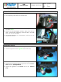
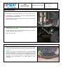
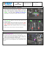
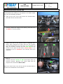
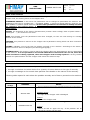
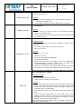
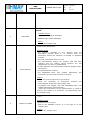
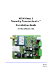
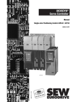
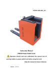
ADJUSTMENTS
AND
INSPECTIONS
GAMMA 66-83-108
Doc.
Emesso
Rev.
10004918
12/2006
00
Pag.
1 di 13
ADJUSTMENTS AND INSPECTIONS
READ THE OPERATING AND MAINTENANCE MANUAL
Electrical Equipment Inspection
1. Disconnect the battery plug.
2. Verify the cleanliness and the tightening of the battery
terminals.
3. Check the connection and the tightening of the power
cables: remote control switches, fuses, motors, etc.
4. Re-connect the battery connector.
5. Check the signal lamps and the switches:
•
Check the functioning of the manipulators of the rise
and descent of the brushes base (on models where
the actuator is provided)
•
Check the switch with signal lamp and the brushes
motor (with the machine functioning).
•
Check the signal lamp of the water cock and the
solenoid valve (with the machine functioning).
•
Check the switch with signal lamp and the suction
motor.
•
Verify the forward and backward movement, the
acceleration and the braking.
•
Check the operation of the hourmeter.
•
Check the operation of the solenoid valve.
ADJUSTMENTS
AND
INSPECTIONS
GAMMA 66-83-108
Inspection Water Supply
Check the cleanliness and positioning of the solution filter :
1. Fill completely with water the solution tank
2. Check the tightness of the hoses and the adjustment of
the water cock
3. Check that the detergent solution, when the cock is
open, arrives with continuity onto the floor and that
there are not any leakages.
4. Check then that with the closed water cock there is not
any solution outlet.
Inspection Suction
1. Check the cleanliness and functionality of the filter float.
2. Check the tightness of the gasket on the filter cap
3. Check the air seal of the cover on the recovery tank.
4. Check the connections and the tightness of the suction
hose and the squeegee hose.
5. Check the tightness of the hose and of the exhaust
plug.
Doc.
Emesso
Rev.
10004918
12/2006
00
Pag.
2 di 13
ADJUSTMENTS
AND
INSPECTIONS
GAMMA 66-83-108
Adjustment Brake
Adjustment hand and working brake:
1. Check that the releases of the lever are not more than 3.
2. If necessary, re-establish the correct range adjusting the
lock nuts of the brake cable.
3. Check that the red signal lamp of the brake is connected
with the first release.
4. Adjustment brake pads: check the braking uniformity,
with the brake inserted
5. trying with the drive, and checking that, the wheels
remain blocked at the same time.
6. Block the lock nuts.
Adjustment Squeegee
1. Adjust the inclination register of the rear squeegee
rubber when the squeegee is in function, so that this has
an even bending through the whole squeegee. Block the
ring nut.
2. Adjust the height of the wheels with the suitable wing
nut checking that the rubber has an inclination of around
30°-45° and that it is not too much pressed down onto
the floor nor too much lifted. The rubber has to be
uniformly tilted backwards in its whole length of the
squeegee.
Doc.
Emesso
Rev.
10004918
12/2006
00
Pag.
3 di 13
ADJUSTMENTS
AND
INSPECTIONS
GAMMA 66-83-108
Adjustment Brushes Gamma 66 / Gamma 83
1. Adjustment inclination during working operation: lower
the brushes base and adjust the support so that the
brush during the descent touches the floor in the rear
part; in the front part it should remain lifted about
5/8mm. To increase the inclination, loosen the four
screws, move the support forwards or backwards
depending on the specific necessity and lock the screws.
2. Adjust the uniformity of the two brushes unscrewing the
two lock nuts placed on the two lower arms of the
pressure screws.
3. Leaving a light print of the brushes on the floor, check
their uniformity. In case of need, act upon the screws
right and left previously loosened from the lock nut:
screwing down more pressure will be on the related
brush.
4. Block the two lock nuts at the end of the operation.
Tension screw belt Gamma 66
Check the tension screw:
1. The screw head must rest on the reduction gear.
2. Between the screw head and the reduction gear there
does not have to be any clearance, and it should not
force too much against the reduction gear.
This screw permits to maintain a correct belt tension, and at
the same time a correct alignment of the transmission shaft
is given.
Doc.
Emesso
Rev.
10004918
12/2006
00
Pag.
4 di 13
ADJUSTMENTS
AND
INSPECTIONS
GAMMA 66-83-108
Adjustment Brushes Gamma 108
In case an uniform alignment of the brushes is not achieved,
and therefore the cleaning is not perfect in its whole width,
carry out the following operation:
1. Take off the front cover that covers the brushes base,
then take off the central brush.
2. Unscrew the two lock nuts of the screws M10 for the
pressure, adjust the length of the spring, that has to be
of 30mm in neutral position.
3. Screw down the two screws until an inclination in the
upper front part of the brushes base is obtained, then
check when lowering the base that the two brushes
touch simultaneously in the rear part; if it is necessary to
align the brushes, unscrew the two lock nuts on the
screws of the right and left arms; screw down if it is
necessary to lift or unscrew if the contrary has to be
obtained.
4. Lift the brushes base, couple the central brush, then
lower it
5. unscrew the two screws of M10 and make work the
pressure springs. Between the screw head and the
support there should be about 2mm .
Block then all the lock nuts, and try with the brushes base in
pressure the steadiness of the machine.
Doc.
Emesso
Rev.
10004918
12/2006
00
Pag.
5 di 13
ADJUSTMENTS
AND
INSPECTIONS
GAMMA 66-83-108
Doc.
Emesso
Rev.
10004918
12/2006
00
Pag.
6 di 13
Menu of the Console
HEADING: the features of the console and of the chopper card: voltage and maximum current of the
chopper card, the working hours of the chopper card.
PARAMETER CHANGE: in this menu the parameters can be changed to personalise the machine. The
parameters that can be modified are : CUT BACK SPEED 1 (minimum speed machine) and the CUT
BACK SPEED 2 (medium speed machine). All the other parameters are decided in Fimap and they
are related to the traction motor. It is forbidden to change them without previous Fimap
authorisation.
TESTER: the quantities of the electric characteristics (traction motor voltage, state of power switch =
closed/open ...) are showed in this menu.
SAVE: this permits, once the parameters have been changed, to enter the new setting in a storage
location of the console.
RESTORE: this permits to restore on the chopper card a parameter setting which has been entered in
the console.
ALARMS: indicates a list of the last five alarms occurred on the machine. According to the alarm a
specific corrective action is adopted (see following paragraph).
PROGRAM VACC: this section is used to teach the chopper about the potentiometer which is assembled
on the machine. It is an operation to be carried when there is the alarm Vacc not ok, when the
pedal accelerator is being replaced, when the chopper card is being replaced. A wrong relation
between the potentiometer and the chopper card causes the machine stop.
Alarms and Decoder
The chopper card visualises an anomaly on two levels of information
1. through a red alarm led which blinks for a quantity of times relative to the type of anomaly
2. through a message on the console that specifies more details on the nature of the anomaly.
Following table reports for each alarm the possible anomaly and of how to proceed on the machine.
Number of
blinkings
MESSAGE
NOTES
The test of self-diagnosis of the chopper card carried out both on rest as in drive verifies
an anomaly
1
WATCH DOG
Possible causes
- the logic of the chopper card is damaged
Actions
- replace the chopper card
The data of the hourmeter inside the chopper card
1
EEPROM DATA KO
Actions
- switch
off and on again the key. If the problem will be
solved the counter will be reset.
ADJUSTMENTS
AND
INSPECTIONS
GAMMA 66-83-108
Doc.
Emesso
Rev.
10004918
12/2006
00
Pag.
7 di 13
The data of the hourmeter and of the alarm stored in the chopper
card are not correct
1
EEPROM OFF LINE
Actions
- switch off and on again the key. If the problem persists
replace the chopper card
- if the problem will be solved the data will be cancelled
The memory of the chopper card has lost the adjustment and
operation data
1
EEPROM PAR KO
Actions
- switch
off and on again the key. If the problem persists
replace the chopper card
- if the problem will be solved the data will be replaced with
the standard data
Incorrect starting sequence
Possible causes
- error
in the sequence Key/drive selection made by the
operator
- the micro pedal and/or micro drive are stuck
- wiring not correct
Actions
2
INCORRECT START
check the starting sequence which is:
- switch on the key
- select drive (forwards/backwards)
- press the accelerator
- check that the drive microswitch
and the manipulator
forward/backward traverse selector do not have the
contacts stuck and that they work correctly
- verify
the continuity of the circuit that connects the micro
drive pedal, the chopper card and the drive manipulator.
The first check recognises a voltage VMN lower than the
25% of the battery voltage
Possible causes
- wrong connections on the motor
- motor current leakage to the ground
Actions
- check
3
VMN LOW
that the motor terminals are well isolated from the
motor casing both inside and outside the motor. Verify that
there is not dirt that causes current leakage between the
terminals and the motor body
- verify that the motor is not wet and in case dry with an air
flow
- check
that the connections on the motor and on the
chopper card are correct (verify the type of traction motor
assembled, the correct wiring and the connections on the
chopper VMN, positive and negative)
if the problem persists replace first the chopper card and, if
necessary, also the motor
ADJUSTMENTS
AND
INSPECTIONS
GAMMA 66-83-108
Doc.
Emesso
Rev.
10004918
12/2006
00
Pag.
8 di 13
Starting test check possible faults on the power circuit
branch .
Possible causes
3
VMN HIGH
-
chopper power branch damaged
MOSFET logic control damaged
Action
-
replace the chopper card
The chopper card recognizes an anomaly in the mechanical
stroke of the accelerator
Possible causes
- the
operator switched on the machine with the
accelerator pressed down or he pressed down the
accelerator before the selection of forward or backward
traverse
- the seat microswitch does not work
- the potentiometer and/or the chopper
card has been
changed and the relating values between the two
components are to be re-programmed
- a cable between the potentiometer and the chopper card is
4
VACC NOT OK
interrupted
- the potentiometer is faulty
- the PROGRAM VACC (see
chapter Adjustment
Inspection) has not been carried out correctly
and
Actions
- check the correct sequence to get traverse
- check
the continuity of connections between
potentiometer accelerator and chopper card
the
- re-program
the chopper card with PROGRAM VACC (see
chapter Adjustment and Inspection)
- check the functionality of the potentiometer (it could be
broken) and replace it if necessary (re-programming then
the chopper card)
The chopper card tests if on rest the signal of the current is zero. Otherwise, it blocks the
traction
Possible causes
5
I HIGH AT STAND
- defective current sensor
- fault in the feedback circuits,
chopper card
Actions
- replace the chopper card
or in the logic or on the
ADJUSTMENTS
AND
INSPECTIONS
GAMMA 66-83-108
Doc.
Emesso
Rev.
10004918
12/2006
00
Pag.
9 di 13
Test on working condition: the negative point brings is
at a wrong
Possible causes
- the potentiometer is not well connected to the chopper
6
card
NPOT NOT OK
- potentiometer defected
Actions
- check the good connections potentiometer – chopper card
- check the potentiometer efficiency
The chopper card works out of the temperature range
(-30°C + 70°C)
Possible causes
7
TH PROTECTION
- chopper card faulty
- the machine runs in braking condition and the chopper gets
overheated
Actions
-
check the temperature of the site where the machine works
check the consumption of the traction motor
The driver that controls the driver power switch do not operate properly
Possible causes
8
DRIVER SHORTED
COIL SHORTED
-
the driver is defected
Actions
32
permanent
BATTERY LOW
blink
replace the chopper card
Battery level too low: the chopper card cuts the power to the
traction motor for its safeguard
Actions
check the charge of the batteries
check the cleanliness and the good connections on the
chopper card of the cable that come from the battery
The alarm is indicated when both the forward and backward
requests are activated simultaneously
Possible causes
permanent
switched on
FORW BACK
- wiring not correct
- microswitch forward or backward stuck
Actions
- check
the correct functionality of the contacts of the
manipulator
-
verify the wiring relative to the manipulator
if the defect persists replace the chopper card
ADJUSTMENTS
AND
INSPECTIONS
GAMMA 66-83-108
Doc.
Emesso
Rev.
10004918
12/2006
00
Pag.
10 di 13
Programming of the Chopper card
FOR A MORE DETAILED DESCRIPTION CONSULT THE
USER MANUAL AND THE FUNCTIONAL DESCRIPTION OF
THE CHOPPER ZAPI.
1. Switch OFF the general key and plug the console in the
special connector. The OFF condition is necessary to save
the memory card from loss of data.
2. Switch on the machine (key ON).
MX
3. It appears: model of the chopper card, voltage, ampere – working
hours of the machine
HOURS
v.2.1
.0
4. Press ENTER to get the main menu
5. You read the first option of the main menu: PROGRAM = CHANGE OF
PARAMETERS
SELECT
6. Press ENTER and check, using the button ROLL, if the values of the
parameters are the ones indicated in the below chart:
CHOPPER MX GAMMA 66/83/108
MENU
PROGRAM
GAMMA 66/83
GAMMA 108
ACCELERATION DELAY
3
3
CUTBACK SPEED 1
0
0
CUTBACK SPEED 2
6
6
COMPENSATION
4
4
TRACTION IMAX
9
9
BRAKING
5
5
RELEASE BRAKING
2
1
SPEED LIMIT BRAKING
4
1
MAX SPEED FORWARD
9
9
MAX SPEED BACKWARD
8
8
CREEP SPEED
2
2
ADJUSTMENTS
AND
INSPECTIONS
GAMMA 66-83-108
Doc.
Emesso
Rev.
10004918
12/2006
00
Pag.
11 di 13
7. At the end press OUT and confirm ENTER if some parameters have been changed.
ATTENTION: YOU ARE FORBIDDEN TO CHANGE ANY PARAMETERS RELATED TO THE
SAFETY USE CONDITION OF THE MACHINE LIKE THE ONES RELATED TO
ACCELERATION, BRAKING, ETC. ONLY THE DIFFERENT SPEED REDUCTION VALUES CAN
BE MODIFIED (CUTBACK SPEED 1 – 2)
8. Select with ROLL "RESTORE PARAM." (in case of memory loss of
the chopper) = REPROGRAMMING CHOPPER PARAMETERS
SELECT
MENU
RESTORE PARAM.
9. Press ENTER
10. It appears the code of the program 00 (it is possible to store
inside the console up to 5 programs numbered from 01 to 05)
SELECT: Mod. 00
11. Press ENTER to confirm the restoring of the program
12. The confirmation request of the operation appears:
ENTER = SI, OUT = NO
ARE YOU SURE?
YES=ENTER NO=OUT
13. Press ENTER to confirm the restoring operation
WAIT!
14. The message WAIT appears
15. At the end of the operation it appears
16. Run through the menus with ROLL UP from RESTORE to
PROGRAM VACC = PROGRAMMING VOLT ACCELERATOR PEDAL
SELECT MENU
RESTORE
SELECT MENU
RESTORE PARAM.
17. Stop your run when you read “PROGRAM VACC”
SELECT
18. Press ENTER to go into the menu “PROGRAM VACC”
PROGRAM VACC
19. The actual maximum values appear which refer to the forward
and backward movement
VACC SETTING
4,8
MENU
4,8
20. Press ENTER
21. Now the chopper is ready to read the minimum and maximum
value of the potentiometer signal
22. Press the lever for the forward movement paying attention to
move slowly at the beginning of the stroke and to get at the
0.0
0.0
ADJUSTMENTS
AND
INSPECTIONS
GAMMA 66-83-108
Doc.
Emesso
Rev.
10004918
12/2006
00
Pag.
12 di 13
end of the stroke
23. Repeat the operation with the backward movement
24. On the screen the new values min and max appear on both
forward and backward movement
FORW
BACK
4,4
4,4
25. Press ENTER
26. The request of confirmation for the new value appears
ARE YOU SURE?
YES = ENTER
NO = OUT
27. Press ENTER to confirm
28. Run through the different menus with ROLL UP or ROLL DOWN
from “PROGRAM VACC” up to the heading
29. Press OUT to come back to the main heading. Switch off the key
and then disconnect the console from the chopper card
SELECT
MENU
PROGRAM
MX
V.2.1
HOURS
General check of the machine
Check that all switches and signal lamps operate properly:
- Brushes base
- Suction motor
- Solenoid valve (if the optional kit is present)
- Brushes motor
- Parking brake
- Check the display for the charge level of the batteries
- Check the good operation of the hourmeter
- Check the good operation of the speed commutator
- Check the condition of the batteries, terminals and cables
Functional tests of the machine
- Fill the tanks with water and check eventual leakages
- Check the sealing of the whole water unit and the uniform falling of the water onto the brushes
- Make the correct adjustments of the squeegee and test
- Adjust the brushes base inclination and test
- Adjust the front splash guard and test
- Check the efficiency of the brake system
- Brake at the maximum speed and check that the wheels stop simultaneously
- Verify: forward and backward movement, speed reductions, acceleration and braking
ADJUSTMENTS
AND
INSPECTIONS
GAMMA 66-83-108
Periodic check differential
1. Differential: check the quantity of grease in the
differential. If necessary, add through the grease
nipple. Use grease of type SHELL Super Grease EPO
or another type with the similar characteristics.
2. Check the clearance of the chain adjusting it if
necessary, through the adjuster in the rear lower part.
Final check
Check all the functions: scrubbing, drying and drive
Doc.
Emesso
Rev.
10004918
12/2006
00
Pag.
13 di 13