1
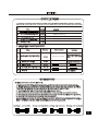
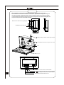
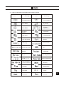
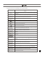
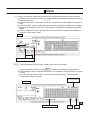
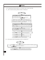
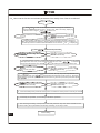
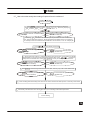
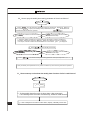
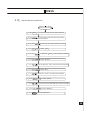
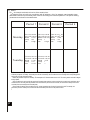
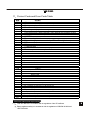
ENGLISH
E-II-AMR09Y
INSTALLATION MANUAL
& USER GUIDE
WEEKLY CENTRALIZED CONTROLLER
AMR09Y
For correct installation, read this manual before starting installation.
Only trained and qualified service personnel should install, repair or service air conditioning equipment. Users
should not install the air conditioner by themselves.
All pictures are only sketches. If there is any difference between pictures in this manual and the actual shape
of the air conditioner you purchased, the actual shape shall prevail.
Installation
Safety Precautions
Read this specifications manual carefully before using the equipment.
This specification manual describes the conditions of operating the centralized controller and its control functions.
Warning
Indicates that an improper operation may cause human death or serious injury.
Caution Indicates that an improper operation may cause human injury or material damage.
For convenience of future reference, keep this manual properly after reading it.
Warning
Dealers or professional staffs shall be consigned to carry on installation, otherwise electric shock or fire accident may be caused by improper installation.
Conduct installation strictly according to this installation instruction. Improper installation may lead to electric shock or fire accident.
Reinstallation shall be conducted by professional staffs, otherwise electric shock or fire accident may be caused by improper installation.
Do not disassembly or assembly it randomly. Random disassembly and assembly may cause the abnormal operating and heating of the air conditioning
system, thus leading to fire accident.
Caution
Do not install it in the place with the flammable gas leakage. Once the flammable gas leaks, the leakage will stay among the surrounding of the weekly
timer and cause fire accident.
The wiring shall adapt to the current of weekly-timer central controller, otherwise it is easy to cause the leakage and heating, thus leading to fire accident.
System Wiring Instructions
•
Connecting diagram for air-conditioning system with central network
Correct connecting diagram 1
Correct connecting diagram 2
2 Other relevant explanation (There are two kinds of indoor unit, namely indoor unit with
built-in network module or external network module.)
Indoor
MD-NIM01
XYE
Installation
Accessory List and Items
The following is the packing list of the weekly-timer central controller MD-CCM09. Confirm whether it contains all accessories.
Num
Name
Quantity
1
2
3
4
5
Remarks
one piece
AMR09Y
Cross recessed pan head tapping screw
six pieces
GB845/ST3.8X25-C-H (S)
Plastic expansion tube
six pieces
Ø 6x30
Installation and operating instructions
one piece
E-II-AMR09Y
Matching resistor
four piece
120
4 Field installation accessories prepared
Num
Quantity
Name
Model selected
Remarks
one piece
RVVP-300/300 3x1 mm2
Used for communicating with the
indoor unit of the air conditioning
system
Three-core cable
one piece
RVV-300/500 3x1.5 mm2
Used for the supplying power to the
weekly-timer central controller
Switch case
one piece
Three-core shielded cable
Cable tubes (plug sleeve, anti-loosening screw)
three piece
several
Cable tie
Used for binding cable (according to
the specific situation)
Installation Instructions
Installation instructions to the central controller:
1 Directly connect 20V~50/60Hz power supply to ends L and N of the socket on the back of the central controller.
2 The signal cable and power cable of the central controller cannot be contained in the same cable tube. The distance
between the signal cable tube and power cable tube shall be between 300 mm -500 mm at least.
3 The total signal cable length of the central controller shall not exceed 1, 200 m.
4 Make sure there is no joint in the middle of the shielded cable. If such a joint exists, use a socket to connect it.
5 After finishing the connection of the central controller, do not use megger to check the insulation of the signal cable.
6 Connecting mode between the central controller and network interface:
The communication port between the central controller and the network interface of the air conditioning system is polar.
The X, Y, and E pins on both sides shall be corresponding and cannot be cross-connected.
Installation
5,The installation method of the central controller using electrician switch case
The thickness of the central controller cable shall be adjusted according to the length of
the cable. A proper cable tube shall be used to install the cable of the central controller.
Insert the flat tip screwdriver into the recess on the top panel of the case and slightly turn
to open the top cover of the central controller.
Dimension: as shown in the right diagram
Installation screw hole (four)
Slightly turn flat tip screwdriver to open the top cover (two)
Screws (GB845/ST3.9*25) used for fixing the central controller
base
Top cover
Y E
L N
OFF
ON
COM
Power connector of the central controller 220V/AC
OFF
ON
COM Emergency Stop Switch, used to shut down all air conditioners.
COM Emergency Open Switch, used to start up all air conditioners.
Communication interface to the indoor unit
Installation
Installation Method
6,Connecting diagram of network-based air conditioning system (There are two types of indoor units, namely indoor unit
with external network interface module on the main control board or built-in network interface module in the main control board.)
Time
Run Mode
Mode Automation
Cool Heat
Fan Dry
Fan Speed
Weekly-Timer Economy
Run
Off
Electric
Auxiliary
Heater
Set
Swing
Query
Lock
Keyboard
Lock
Remoter
operate
result
Lock
Heat
Lock
Cool
7.1
On-line condition matrix
table of air conditioners
0-63
How to use
7,Indicator description of the weekly-timer central controller
General drawing of the liquid crystal display of the weekly-timer central controller
How to use
7.2 LCD icon description of the weekly-timer central controller
Icon
Icon
Meaning
Automation Mode
Meaning
Fan Only Mode
Cool Mode
Dry Mode
Heat Mode
Fan Speed
High/Middle/Low
Electric
Auxiliary
Heater
Lock Heat
Lock Cool
Lock Remoter
Lock Keyboard
Setting
Operate Result
Querying
Weely Timer Off
All
Online
Protecting
Set Temperature
Error
Period1 2
3
4
T2A Indoor pipe Temperature A
T2B Indoor pipe Temperature B
T3 Outdoor pipe Temperature
Room Temperature
Monday
Tuesday
Wednesday
Thursday
Friday
Saturday
Sunday
Confirm to save
Set Time
Set Airconditioner
Used to select the air conditioner
to be set or queried
Query Airconditiner
Enter the setting page
of the weekly timer
On/Off Weekly-timer
Set
Run Mode
Set Swing
Set Lock
Set
Fan Speed
Reset
How to use
8,Key description of the weekly-timer central controller
8.1 General key layout of the weekly-timer central controller
How to use
8.2
Key instructions of the weekly-timer central controller
Key Name
Usage
Press the ON/OFF button. All air conditioners will be shut down if they are running, on the contrary, they will be started up.If you press the button for less
than 5 seconds, the startup mode is the last running mode of the air conditioner. If you press the button for more than 5 seconds, the startup mode is cooling,
high Speed,24 degrees.
Set
Press the SET button, and then select set single or set all . set single indicates to set the parameter (such as mode/ temperature/
Fan speed/ weekly timer) of an selected air conditioner. set all indicates to set the parameter of all air conditioners controlled by the central controller.
Query
Press the query button to query the running condition of the air conditioner, such as on/off, temperature setting, indoor temperature, running mode
and Fan speed. Press up , down , Left and right to select the air conditioner that you want to query.
When querying or setting the indoor unit, press the up to select the indoor unit to be set or queried.
When querying or setting the indoor unit, press down to select the indoor unit that you want to set or query.
When querying or setting the indoor unit, press Left to select the indoor unit to be set or queried. In setting the weekly timer, it is used for
selecting the day of the week and the time of startup and shutdown.
When querying or setting the indoor unit, press right to select the indoor unit to be set or queried. In setting the weekly timer, it is used for
selecting the day of the week and the time of startup and shutdown.
Add
Reduce
When querying the indoor unit, press the Add button to query more parameter of the indoor unit. In setting the indoor unit, it is for modifying the
setting temperature. In setting the weekly timer, it is for modifying the time of startup and shutdown.
When querying the indoor unit, press the Reduce button to query more parameter of the indoor unit. In setting the indoor unit, it is for modifying
the setting temperature. In setting the weekly timer, it is for modifying the time of startup and shutdown.
Mode
In setting the indoor unit, it is used for setting the running mode of the indoor unit which includes Automation,Cool, Heat, Fan Only, Dry and Off. You can
select among them.
Fan
In setting the indoor unit, it is for setting the wind speed of the indoor unit which includes high speed, middle speed, low speed and automatic speed. You
can select among them.
Swing
Lock
Reset
Program
Weekly
Time
Confirm
Cancel
In setting the indoor unit, it is for setting the swing-function of the indoor unit. The running mode is selected between swing-on and swing-off .
When setting, press the Lock button to lock the remote controller of all or single indoor unit. Press the Query button and hold under the main page,
then repress the Lock button again to lock the keyboard of the central controller; press the Mode button and then repress the Lock button to lock
the running mode.
The central controller re-scans the indoor unit in the network as recharging after power off.
Under the main page, press the Program b utton to set the weekly timer of single indoor unit or all indoor units . Press the Query button
and hold, and then press the Program b utton to query the weekly timer parameters of the indoor unit.
Under the main page, press the Weekly button to start up or shut down the weekly timer function. .
Under the main page, press the Time button for 5 seconds to enter the time-modifying status, and then press Add or Reduce button to modify
the time. Press Left or Right to select minute/ hour/ day/ month/ year. Finally, press the Confirm b utton to save the modification.
Save data and send the command required to the indoor unit, such as setting the mode of the air conditioner.
Cancel the last operation and return to the last interface.
How to use
8.3
The main interface of the weekly-timer central controller (user interface)
Cancel
1 Under the other pages, press
to return to the main interface.
2 Under the other pages, automatically return to the main interface when no operation
for a period of time.
3 The main interface displays the on-line condition of the indoor unit.
Sixty-one indoor units
are on-line.
Date
The on-line condition of the indoor unit
8.4 Setting interface of single weekly-timer central controller
1 Under the main interface, press Set to select to the single setting interface
2 Automatically return to the main interface when no operation for a period of time.
3 Set the running status of single air conditioner under this page.
Indoor Net-address
Room Temprature
28 degree
Set temprature
20 degree
Cool
High Speed
setting
Set Successfully
on
How to use
8.5 Setting interface of weekly timer parameters of single weekly-timer central controller
1 Under the main interface, press
Program to display the parameter setting interface of
single weekly timer
2 Automatically return to the main interface if no operation is performed for a period of
time.
3 Under this page, set the weekly timer parameters of single air conditioner, including
startup time, shutdown time, the running mode of this period, temperature and wind
speed.
4 One air conditioner can be at most set with four periods in one day from Monday to
Sunday, seven days in total.
Period1
Monday
Time on ,Time off
8.6
Unified setting interface of the weekly-timer central controller
Under the main interface, press Set to display the unified setting interface.
Automatically return to the main interface if no operation is performed for a period
of time.
3 Set the running mode of all air conditioners under this page, including mode,
temperature and Fan speed.
1
2
Set unsuccessfully
All indoor
Weekly-timer off
Lock
remoter
Lock
Cool
How to use
9
The operating flow description of the weekly-timer central controller
9.1 How to set the running status of the air conditioner?
Under the main interface
1 Press Set to enter the setting status interface of single air
conditioner. Press the button repeatedly to select Single and
All alternately, display Set .
If you select Single, press
to select one.
2 Selecting All indicates to set the running status of all air
conditioners, and All is displayed. Selecting Single displays
the address of the air conditioner; for example, if the air conditioner
whose address is 12 is selected, 12# is displayed.
3,Press Mode to select running mode: automatic, cooling, heating,
air supply, dehumidification, or shutdown. If you select Shutdown
mode, press Confirm to send shutdown command, finishing shutdown
setting.
4 If you select the cooling or heating mode,
press Add Reduce to adjust the temperature (the scope is
within 17-30 degree). No temperature adjustment for other modes.
5 Press Fan to regulate wind speed, which can be selected among
automatic speed, low speed, middle speed and high speed.
6
Press
Swing
to open or close swing
7 Press Confirm to save the above setting and send to the
corresponding air conditioner, finally finish setting.
9.2 How to query the running status of the air conditioner?
Under the main interface
1 Press Query
Press
2 Press
Add
to enter the query status of single air conditioner, displaying
to select one air conditioner.
Reduce
to view more parameters of the air conditioner.
Query
;
How to use
9.3 How to lock and unlock the remote controller of the air conditioner?
Under the main interface
1 Press Set to enter the setting status interface of single air conditioner,
press the button repeatedly to select Single and All alternately,
displaying Set . If you select Single , press
to select one.
2 Selecting All indicates to set the running status of all air conditioners,
and All is displayed. Selecting Single displays the address of the air
conditioner; for example, if the air conditioner whose address is 12 is selected,
12# is displayed.
3 Press Lock to send the lock or unlock command of the remote controller to the
corresponding air conditioner and finish setting.
9.4 How to lock and unlock the mode of the air conditioner?
Under the main interface
1 Press Mode and hold, then press
interface of the mode-locking.
Lock
, enter the setting
2 If the air conditioner is in the mode of unlocking, press
to select cooling-locking or heating-locking,press Confirm to send
mode-locking command.
3 If the air conditioner is in the mode of locking, press Confirm to send the
selected unlock command to all air conditioners,
9.5 How to lock and unlock the keyboard of the weekly-timer central controller?
Under the main interface
Press and hold Query , and then press
1
2
Lock
The keyboard will be locked if it is unlocked.
If it is locked, it will be unlocked.
.
How to use
9.6 How to set the function and relevant parameters of the weekly timer of the air conditioner?
Under the main interface
1 Press Program to enter the setting status interface of single air conditioner,
press the button repeatedly to select Single and All alternately, displaying
Set ;if select sigle
press
to select one.
Press Confirm to select air conditioner to
the next step
Press
Cancel to cancel the selection and
return to the last step.
2 Selecting All indicates to set the weekly timer parameters of all air conditioners,
and All is displayed. Selecting Single displays the address of the air conditioner;
for example, if the air conditioner whose address is 12 is selected, 12 #
is displayed.
3 Press
to select the day of the week
Press Confirm to select the day of the week
to the next step
Press
Cancel to cancel the selection and
return to the last step.
4 Set the parameter of period 1, including shutdown time, startup time, running mode, Fan speed
and temperature. First of all, set the startup and shutdown time. Press
to select the
startup time and shutdown time. Press Add Reduce to modify the startup and shutdown time.
Press Confirm to save the parameter of the
period 1 to the next step
Press
Cancel to cancel the set of period 1 and
return to the last step.
5 Press Mode to select running mode: automatic, cool, heat, Fan-only , Dry, or Off. If you select the cool ,
automatic or heat mode, press Add Reduce to adjust the temperature (the scope is within 17 - 30 degree).
Press Fan to regulate Fan speed, which can be selected among automatic speed,low Speed,middle speed
and high speed
Press Confirm to save the parameter of the
period 1 to the next step
6
7
Press
Cancel to cancel the set of period 1 and
return to the last step.
Finish the weekly timer parameter setting of the air conditioner within period 1 of the day of the week.
Continually set periods 2, 3, 4 according to the above operation.
8 After finishing the setting of the periods, continually select the day of the week needed to be set,
to set the weekly timer parameter from Monday to Sunday, seven days in total.
Finish setting
How to use
9.7 How to close the weekly timer setting of a period of an air conditioner?
Under the main interface
1 Press Program to enter the setting status interface of single air conditioner,
press the button repeatedly to select Single and All alternately, displaying
Set ;if select sigle
press
to select one.
Press Confirm to select air conditioner to
the next step
Press
Cancel to cancel the selection and
return to the last step.
2 Selecting All indicates to set the weekly timer parameters of all air conditioners,
and All is displayed. Selecting Single displays the address of the air conditioner;
for example, if the air conditioner whose address is 12 is selected, 12 #
is displayed.
3 Press
to select the day of the week
Press Confirm to select the day of the week
to the next step
Press
Cancel to cancel the selection and
return to the last step.
4 Set the parameter of period 1, including shutdown time, startup time, running mode, Fan speed
and temperature. First of all, set the startup and shutdown time. Press
to select the
startup time and shutdown time. Press Add Reduce to modify the startup and shutdown time.
Press Confirm to save the parameter of the
period 1 to the next step
Press
Cancel to cancel the set of period 1 and
return to the last step.
5 Press Mode to select running mode: automatic, cool, heat, Fan-only , Dry, or Off. select Off
Press Confirm to save the parameter of the
period 1 to the next step
6
7
Press
mode.
Cancel to cancel the set of period 1 and
return to the last step.
Finish shutting down the weekly timer function of the air conditioner within period 1 of the day of the week.
Continually shut down the timer during periods 2, 3, 4 according to the above operation.
Finish setting
How to use
9.8 How to query the weekly timer setting parameter of the air conditioner?
Under the main interface
1 Press Query to enter the query status of single air conditioner, displaying Query .
Then press Program to query the weekly timer parameters. Press
to select the air
conditioner that needs to be queried.
Press Confirm to select air conditioner to
the next step
Press
Cancel to cancel the selection and
return to the last step.
2 Selecting All indicates to set the weekly timer parameters of all air conditioners,
and All is displayed. Selecting Single displays the address of the air conditioner;
for example, if the air conditioner whose address is 12 is selected, 12 #
is displayed.
3 Press
to select the day of the week
Press Confirm to select the day of the week
to the next step
4 Press
Press
Cancel to cancel the selection and
return to the last step.
to select the weekly timer setting parameter of the queried periods 1, 2, 3, 4.
Query the weekly timer parameters of any indoor unit within any time according to the above operation.
9.9 How to start up or shut down the weekly timer function of all air conditioners?
Under the main interface
1
Press
Weekly
If the weekly timer function is shut down, then start up it;
if the weekly timer function is started up, and then shut down it.
2
3
If the weekly timer function is shut down, display
Weekly Timer Off
How to use
9.10
How to modify the system time?
Under the main interface
1
Press Time
for 5 seconds, enter the time-setting interface.
2 Press
for a long time to select the minute/ hour/ day/
month/ year that need to be modified.
3
First, press
4 Press
5
Reduce
modify
Add
Reduce
Add
Reduce
modify
to select the
9 Press
10 Press
modify
Month
Add
Reduce
Day
10 Press
Add
9 Press
Confirm
Reduce
that needs to be modified.
Day
Hour
to modify
that needs to be modified.
Hour
again to select the
11 Press
that needs to be modified.
Month
again to select the
Press
8 Press
Year
to select the
then Press
6 Press
7
Add
to select the Year that needs to be modified.
to modify
Minute
Minute
to save the modification
that need to be modified.
10 Others
10.1 An example to show the function of the weekly timer
1 Take the indoor unit of the air conditioner with an address 04 for example, set the weekly timer
parameters and start up the weekly timer function according to the above operation. The specific setting
parameter is as shown in the table below:
Period 1
Period 2
Period 3
Monday
Time on =07:30
Time off =18:00
Mode = cool
Temp = 24
Fan
= High
Time on =18:30
Time off =21:00
Mode= Fan-only
Temp =
Fan
= High
Time on =21 30
Time off =23 30
Mode = cool
Temp = 24
Fan
= High
Tuesday
Time on =07:30
Time off =18:00
Mode = cool
Temp = 24
Fan
= Low
Time on =18:30
Time off =19:00
Mode = Off
Temp =
Fan
=
Period 4
From the above table, we can see that the indoor unit has been set weekly timer parameters for two days every week, namely period 1, 2, 3
of Monday and period 1 of Tuesday. If the weekly timer function is started up, the air conditioner will run according to the corresponding period
setting when it is within the specific period.
Notes to the parameter of period 1 of Monday: The startup time is 07:30 and shutdown time is 18:30. The running mode is cool with 24 degree
and high Speed.
If the air conditioner is running within the set period of the weekly timer and there is other control device to control the air conditioner, the air
conditioner will run according to the set parameter of the control devices (such as remote controller, line controller and weekly-timer central
controller) till to the next set period of the weekly timer.
If the set mode of a period of the air conditioner is Off, it means the weekly timer function of the period is invalid. For example, the
set mode of period 2 of Tuesday is Off, which shows that the set weekly timer function of the period is invalid.
•
How to use
11
Protect Code and Error Code Table
EF
EE
ED
EC
EB
EA
E9
E8
E7
E6
E5
E4
E3
E2
E1
E0
07#
06#
05#
04#
03#
02#
01#
00#
PF
PE
PD
PC
PB
PA
P9
P8
P7
P6
P5
P4
P3
P2
P1
P0
3
od
ree
ir
Other faults
Water-level detection fault
Fault protection of the outdoor unit
Freshness fault
Inverter module protect
Excess flow of compressor (four times)
Communication fault between main board and display board
Losing control of wind speed examination
EEPROM error
Zero-crossing detection error
Exhaust temperature sensor faulty of T3 or T4 or digital compressor
T2B sensor fault
T2A sensor fault
T1 sensor fault
Communication fault
Phase-sequence error or phase-failure
Communication fault between the central controller and the network interface module
Communication fault between the network interface module and the main control board
Other protection measures
Reserved
Reserved
Reserved
Reserved
Reserved
Reserved
Excess flow of compressor
Over-voltage or under-voltage protection
Low-voltage protection of air exhaust
High-voltage protection of air exhaust
Temperature protection of exhaust pipe
Temperature protection of compressor
High temperature protection of condenser
Cold air-proof or defrosting-proof protection
Temperature protection of evaporator
Technical indices and requirements
••••
EMC and EMI are in accordance with the regulations of the CE certificate.
Electric appliance safety is in accordance with the regulations of GB4706.32-2004 and
GB/T7725-2004.
DE - COMMISSIONING DISMANTLING & DISPOSAL
This product contains refrigerant under pressure, rotating parts, and electrical connections which
may be a danger and cause injury!
All work must only be carried out by competent persons using suitable protective clothing and safety precautions.
Read the Manual
Risk of electric shock
Unit is remotely controlled
and may start without warning
1. Isolate all sources of electrical supply to the unit including any control system supplies switched by the unit. Ensure that all points of electrical and gas
isolation are secured in the OFF position. The supply cables and gas pipework may then be disconnected and removed. For points of connection refer
to unit installation instructions.
2. Remove all refrigerant from each system of the unit into a suitable container using a refrigerant reclaim or recovery unit. This refrigerant may then be
re-used, if appropriate, or returned to the manufacturer for disposal.Under No circumstances should refrigerant be vented to atmosphere. Where
appropriate, drain the refrigerant oil from each system into a suitable container and dispose of according to local laws and regulations governing
disposal of oily wastes.
3. Packaged unit can generally be removed in one piece after disconnection as above. Any fixing down bolts should be removed and then unit lifted from
position using the points provided and equipment of adequate lifting capacity. Reference MUST be made to the unit installation instructions for unit
weight and correct methods of lifting. Note that any residual or spilt refrigerant oil should be mopped up and disposed of as described above.
4. After removal from position the unit parts may be disposed of according to local laws and regulations.
E-II-AMR09Y
ENGLISH