1
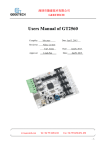
RADDS
RAPS128
RepRap Arduino-Due Driver Shield
RADDS Power Stepper Driver with
1/128 Microstepping
HALL-E
LCD-DISPLAY
Hall Effect Endstop
RADDS LCD Control Panel
Next Generation 32-Bit RepRap Set
Userguide created by @mundsen
V 2 – Feb 2015
ATTRIBUTION-NONCOMMERCIAL-SHAREALIKE 3.0 UNPORTED (CC BY-NC-SA 3.0)
UserGuide_V2_ooznest
Page 2 of 44
Table of Contents
1
INTRODUCTION............................................................................................................................. 5
2
RADDS ............................................................................................................................................ 6
3
4
5
6
2.1
FEATURES ................................................................................................................................. 6
2.2
W IRING DIAGRAM ....................................................................................................................... 8
2.3
PIN DEFINITIONS AND DIMENSIONS .............................................................................................. 9
2.4
SET MICRO STEPPING MODE .....................................................................................................10
2.5
INSTALL STEPPER DRIVERS LIKE A4988, DRV8825 OR RAPS128...............................................14
2.6
CONNECT STEPPER MOTORS ....................................................................................................15
2.7
CONNECT END STOPS ..............................................................................................................18
2.8
EXTENSION BOARD ..................................................................................................................19
2.9
ARDUINO DUE.........................................................................................................................20
2.10
UDOO QUAD .........................................................................................................................20
RAPS128.......................................................................................................................................21
3.1
FEATURES ...............................................................................................................................21
3.2
VERSION TRACKER ..................................................................................................................22
3.3
W IRING ...................................................................................................................................22
3.4
ADJUST V-REF .......................................................................................................................23
3.5
ADJUST DECAY ........................................................................................................................23
HALL-E ..........................................................................................................................................24
4.1
FEATURES ...............................................................................................................................24
4.2
W IRING ...................................................................................................................................24
4.3
PIN DEFINITIONS ......................................................................................................................25
4.4
DIMENSIONS ............................................................................................................................25
4.5
MAGNET PLACEMENT ...............................................................................................................26
4.6
OPTION FOR EXTRA-ACCURATE ADJUSTMENT ............................................................................27
LCD PANEL ..................................................................................................................................29
5.1
FEATURES ...............................................................................................................................29
5.2
W IRING ...................................................................................................................................30
5.3
DIMENSIONS ............................................................................................................................30
OTHER ELECTRONICS ...............................................................................................................31
UserGuide V2
Page 3 of 44
6.1
EXTRUDER/HOT END ...............................................................................................................31
6.2
PSU (POWER SUPPLY UNIT) AND ELECTRICAL GOOD SIZING ......................................................32
7
SOFTWARE ..................................................................................................................................40
7.1
ARDUINO SOFTWARE ................................................................................................................40
7.2
REPETIER ................................................................................................................................40
7.3
MARLIN ...................................................................................................................................40
8
APPENDIX B – WEB LINKS .........................................................................................................41
9
NOTES ..........................................................................................................................................42
10
YOUR SETTINGS .....................................................................................................................43
UserGuide_V2_ooznest
Page 4 of 44
1 Introduction
These products were directly inspired by things I found in the RepRap communities, and are the
consequence of a continuous improvement effort.
My first printer was a Rostock mini that I had cloned. At that time, I had no knowledge about 3D
printers, but I found the idea of printing a toy for my son so awesome that I wanted to learn more
about the subject.
I was indeed impressed by the printing result when - after months - I was finally able to breathe
life into my Rostock Mini. However, when measuring the printed objects with the calipers, the
disillusionment came :-).
Then I`ve built my second delta built with a similar result. Only now, I began to think :-).
How do I get a reliable quality print result?
What mechanism is stiff enough to not only to be accurate but also able to handle fast printing?
What do I need to achieve these goals? And so on.
As a mechanical engineer, I quite quickly had a rough idea for the mechanics of a clever delta
printer design.
Now what do I need to achieve an acceptable position accuracy / precision???
First, I had to solve the electronics, and started googling to find a way to achieve what I want.
In the German RepRap forum, I stumbled on a little known solution made by Dr. Martin
Henschke - The RADDS-Shield!!!
It is a daughterboard for the 32-bit Arduino Due, similar to the RAMPS, the 8-bit daughterboard
for Arduino Mega. However, this solution offers much more calculation power then the current 8bit CPU, plenty of power. Although it was a beta and prototype state, it seems to be wellworking. I just thought it might work.
I want a controller like that!!!
However, I have a big problem, I have no idea of electronics and certainly do not know anything
about soldering - now what? A long odyssey began, but now it is done.
Now you can simply order the RADDS-Shield, associated components, and bless your printer
with it :-).
Enough said for now ... Have Fun...
Angelo
UserGuide V2
Page 5 of 44
2 RADDS
2.1 Features
This guide describes RADDS 1.2 and 1.5 (For the older RADDS 1.1 use the RADDS 1.1
guide)
The RADDS-Board provides the following connectivity’s:
•
6 Steppers on-board : X,Y,Z, E0, E1, E2. (Sample: 3 axis and 3 extruders (Z-axis, and
E3 extruder, comes with 2 pins strips for optional second stepper).
•
6 Heavy duty MOSFET`s (Sample: 1 HeatBed, 3 HotEnds and 2 fans)
•
SD-Card (micro-SD-slot onboard, optional external SD-slot)
•
Standard LCD (5V) with 4x20 characters (HD44780 compatible)
•
Rotating encoder (on LCD panel)
•
6 endstops (Xmin,Ymin,Zmin,Xmax,Ymax;Zmax)
•
5 thermistors and an ADC
•
3 servomotors
•
I2C, SPI, CAN, DAC, RS232 and 8 digital-pins available via pin strips
Additional Features:
•
EEPROM
•
Control-LEDs for loads and operation voltage
•
Catch-diodes on the MOSFET`s
•
Car-fuses instead of thermo fuses
•
Variable input voltage: can be supplied from 10V up to 25V
•
Heatbed electronic control supports up to15A without a heatsink
•
Premium screw terminals
•
12bit ADC (analog to digital converter) upgraded from 10 to 12 bit. Now temperature
calculation is done on 4096 measure points instead of 1024, what give a read
temperature with 4x better resolution. Combined to a new firmware algorithm that uses
660 measure points to extrapolate results, a new level of accuracy is reached for reprap
temperature control…
UserGuide_V2_ooznest
Page 6 of 44
Version Tracker
2.1.1 RADDS 1
First edition :-) with 8-pin-SD-extern connector
2.1.2 RADDS 1.1
2 pins for reset and back button (LCD) added (10-pin-SD-extern connector)
2.1.3 RADDS 1.2
DC/DC converter added for 10 - 25 V power supply.
2.1.4 RADDS 1.5
Several layout changes for more stable temperature reading:
•
Heated bed connection separated
•
Motor ground separated up to the green connector
•
Hotend ground separated up to the green connector
•
Better shielded coil at the DC/DC converter and coil moved away from ADC lines
•
220 µF at 3,3 V line added for Due clones with unstable 3,3 V supply
•
100 µF capacitors changed to 47 µF - better for RAPS128 and enough for POLOLUS
•
Better shielded coil at the DC/DC converter and coil moved away from ADC lines
UserGuide V2
Page 7 of 44
2.2 Wiring diagram
UserGuide_V2_ooznest
Page 8 of 44
2.3 Pin definitions and dimensions
Stepper motor pins:
Steppers
Coil 1
Coil2
Pololu
RAPS-128
Pin
11
1
1B
1A
12
2
1A
2A
21
1
2A
1B
22
2
2B
2B
UserGuide V2
Page 9 of 44
2.4 Set micro stepping mode
When you use stepper drivers like the A4988, DRV8825 and RAPS128 (NOT WHEN USING
EXTERNAL DRIVERS LIKE SILENCIOSO) you have to set the micro stepping mode using the
dipswitches on the back of the RADDS board.
A4988
DRV8825
RAPS128
MS1
MS2
MS3
MS1
MS2
MS3
Off
Off
Off
Off
Off
On
Off
Off
On
Off
On
Off
On
On
On
On
Modes
MS1
MS2
MS3
STEP
Off
Off
Off
Off
1
Off
Off
On
Off
Off
1/2
Off
On
Off
Off
On
Off
1/4
Off
On
On
Off
On
On
Off
1/8
On
Off
Off
On
Off
Off
On
1/16
On
On
On
On
Off
On
1/32
Off
On
On
1/64
On
On
On
1/128
In the table, you find the different stepping modes for usual drivers.
UserGuide_V2_ooznest
Page 10 of 44
When using the DRV8825 the combinations HLH, LHH and HHH all gives 1/32 STEP
Off = Logic low level (not connected or ground). On = logic high level(2-5V)
NOTE: you have to set the same stepping mode in the configuration.h file and update the
controller software
When altering the stepping mode, you have to separate the RADDS board from the Arduino
DUE/UDOO QUAD, because dipswitches are hidden under the RADDS board.
By using this tool, you can remove the RADDS board without making any damages.
Download STL and OpenSCAD files using this URL:
http://www.dr-henschke.de/demount.zip
UserGuide V2
Page 11 of 44
2.4.1 Micro stepping
A stepper motor always has a fixed number of steps. Micro stepping is a way of
increasing the number of steps by sending a sine/cosine waveform to the coils inside
the stepper motor. In most cases, micro stepping allows stepper motors to run
smoother and more accurately.
Micro stepping between pole-positions is made with lower torque than with full
stepping, but has much lower tendency for mechanical oscillation around the steppositions and you can drive with much higher frequencies.
If your motors are near to mechanical limitations and you have high friction or
dynamics, micro steps do not give you much more accuracy over half-stepping. When
your motors are 'overpowered' and/or you do not have much friction, then micro
stepping can give you much higher accuracy over half-stepping. You can transfer the
higher positioning accuracy to moving accuracy too
Source: http://www.reprap.org/wiki/Stepper_motor#Micro_stepping
If you want to alter the micro stepping value on one or more axis, you have to set the correct
value. When using Silencioso, you set it using the dipswitches on the Silencioso and modify the
values in the configuration.h file
Each time you increase the stepping one level (sample: from 1/16 to 1/32) you have to multiply
the steps per unit value by two.
Sample – You are using 1/16 steps per unit and the value is 80 and want to use 1/32 steps per
unit.
If your steps per unit value is 80, you have to multiply 80 by two (2x80).
New steps per unit value = 160
UserGuide_V2_ooznest
Page 12 of 44
// #define DEFAULT_AXIS_STEPS_PER_UNIT
{78.7402,78.7402,200.0*8/3,760*1.1} // default steps per unit for Ultimaker
//#define DEFAULT_AXIS_STEPS_PER_UNIT {80,80,2560,107} // default
steps per unit for OrdBot 1/16
#define DEFAULT_AXIS_STEPS_PER_UNIT {160,160,5120,214} // default
steps per unit for OrdBot 1/32
This code sample is from Marlin.
The “default steps per unit for OrdBot 1/16” gives you the values for 1/16 micro stepping.
80, 80, 2560, 107
X-Axis = 80 steps/mm
Y-Axis = 80 steps/mm
Z-Axis = 2560 steps/mm
Extruder motor = 107 steps/mm (this is the setting for Bulldog Lite Extruder. You have to find
the correct setting for the extruder you use)
In the next code line, you find “default steps per unit for OrdBot 1/32”. This is the settings when
1/32 micro stepping are used. Here all values have been multiplied with two.
UserGuide V2
Page 13 of 44
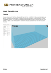
2.5 Install stepper drivers like A4988, DRV8825 or Raps128
Before you install stepper drivers, you have to locate the stepper drivers DIR pin.
When you orientate the RAPS128 like in the image, the DIR pin is in the upper right corner
When you insert the stepper drivers, the drivers DIR pin have to point towards the DIR label on
the RADDS driver socket.
UserGuide_V2_ooznest
Page 14 of 44
2.6 Connect stepper motors
The Z and E3 axis comes with dual motor pin connections so you can connect an additional
stepper easily on these axis..
NOTE: The pins where you connect Z, Y and X stepper motors are in the opposite direction
compared to E1, E2 and E3
UserGuide V2
Page 15 of 44
Sample: A setup where you use dual stepper motors for the Z-axis, X and Y-axis + one extruder.
This is a normal setup on many printers.
With this setup, you have two spare outputs, where E3 have pins for dual steppers in the same
way as the Z-output.
UserGuide_V2_ooznest
Page 16 of 44
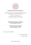
2.6.1 Stepper motors
Before you can connect the stepper motor to RADDS, you need some information on the
stepper motor you have.
Look at your motor, find its part number. Then Google it. Try to find a schematic or a data-sheet
that will indicate which wire goes to which pole. Note the colors that correspond to each coil.
Wiring diagram for Wantai 42BYGHW609 stepper motor (from www.wantamotor.com).
If you can`t find the motor`s part number, you can use another method to find the motor`s pole
pairs.
When two wires for a pole (A +C or B+D) touch together it makes a closed circuit for that pole
and it gets harder to turn the stepper motor.
1.
Try to turn the motor when no cables touch together – it should turn freely.
2.
Touch two of the cables together – if the motor gets harder to turn, you have found a
pole pair. If not, try to touch two other cables together until the motor gets harder to move.
3.
When you have two cables together that makes it harder to turn the motor, you have
found a pole pair.
Note the colors for each pole pair (Pair 1 = BLK + GRN, Pair 2 = RED
+ BLU)
UserGuide V2
Page 17 of 44
On the Wantai 42BYGHw609 the colors are:
11 = Black
12 = Green
21 = Blue
22 = Red
It does not matter if you swap the pole pairs. If the motor turns the wrong way, you can reverse it
in the configuration file.
2.7 Connect end stops
NOTE
when using electronic endstops like the HALL-E end stop, only use endstops that have
max 3,3V out on the signal pin.
Mechanical endstops:
Connect the mechanical endstops to the GND and Signal pins so they are normally closed (push
= open)
UserGuide_V2_ooznest
Page 18 of 44
2.8 Extension board
By using this board, you can get two extra stepper drivers.
Extension board size and pins.
UserGuide V2
Page 19 of 44
2.9 Arduino DUE
The Due has a 32-bit ARM core that can outperform typical 8-bit microcontroller boards. The
most significant differences are:
•
32-bit core.
•
CPU Clock at 84 MHz.
•
96 Kbytes of SRAM.
•
512 Kbytes of Flash memory for code.
Mount the RADDS board on the top of the Arduino DUE.
Use the USB Programming port when connecting the DUE to a computer for software update or
controlling the printer.
2.10 UDOO QUAD
If you want more computer power, you can replace the Arduino DUE with an UDOO QUAD
minicomputer. UDOO QUAD is a minicomputer that can run Linux or Android with an embedded
Arduino DUE http://www.udoo.org/features/
UserGuide_V2_ooznest
Page 20 of 44
3 RAPS128
3.1 Features
•
THB6128 chip
•
Motor voltage 10 - 25V
•
Motor current 0 to 2.2 A adjustable via potentiometer (V-REF)
•
Motor decay adjustable via potentiometer (Decay)
•
Sleep and Boost Mode
•
Logic voltage is generated from the motor voltage
•
Up to 128 micro steps possible (recommended maximum of 32 micro steps for 8-bit
electronics, such as Arduino Mega with RAMPS.)
•
Short Circuit Shutdown
•
Pre-installed heat sink
•
The size corresponds to the popular Pololu drivers and the pinout is compatible but not
identical.
•
Max 1/128 micro stepping when used in combination with RADDS (or other 32-bits
controllers that supports 1/128 micro stepping)
•
Can be used on RAMPS, rumba and other RepRap electronics, but 8-bit electronics
usually are too slow for 1/64 and 1/128 micro stepping.
CAUTION: Inverted activation signal Enable = HIGH (at Pololu drivers enable = LOW, invert
in firmware!)
UserGuide V2
Page 21 of 44
3.2 Version Tracker
V1 - This is the first RAPS128
V2 - C1 change from 10 µF to 0.1µF
3.3 Wiring
3.3.1 Minimal pinout
3.3.2 Maximum pinout
UserGuide_V2_ooznest
Page 22 of 44
3.4 Adjust V-REF
The arrows indicate the measurement points for the reference voltage. Use a voltmeter and
measure the voltage between the ground terminal and the pot wiper on the driver’s v-ref
potentiometer.
Recommended voltage range: 0.8 to 1.6 V. This corresponds to a theoretical peak engine power
from 0.73 to 1.46 A
3.5 Adjust Decay
By turning the decay potentiometer, the way of voltage and current decay in the motor coils is
changed. A medium setting has been proven to work with many Nema 17 motors."
UserGuide V2
Page 23 of 44
4 HALL-E
4.1 Features
•
Hall-effect sensor (magnetic)
•
Operating voltage 3,3V or 5V
•
Potentiometer for sensitive range setup
•
The sensor provides an analog signal that is proportional to the magnetic field strenght
that is compared with the preset value set by the potentiometer.
•
LED that indicates end stop status
•
Includes HALL-E sensor + magnet
4.2 Wiring
Sample: HALL-E end stop connected to RADDS (Ref chapter 2.8 )
UserGuide_V2_ooznest
Page 24 of 44
4.3 Pin definitions
4.4 Dimensions
The mounting holes is 3,2mm in diameter
Position of the hall sensor on the circuit board
UserGuide V2
Page 25 of 44
4.5 Magnet placement
The magnet has red color in this illustration
The sensor will detect the magnetic field of the magnet in the front of itself, as shown by picture
above. If the sensor does not detect the magnet, try to rotate the magnet upside-down,
according the fact that magnets have 2 poles, and only one is detected.
UserGuide_V2_ooznest
Page 26 of 44
4.6 Option for extra-accurate adjustment
Using a spindle potentiometer (5-10 kOhms), adjustment can be made a lot more sensitive.
Only the wiper and one end of the resistor is connected. The third wire is connected to the
potentiometer shield.
You have to disable the internal potentiometer when an external potentiometer is connected. For
this purpose, the stop is bent (1) and the wiper rotated to the exactly middle between the two
ends of the resistance track (2)..
UserGuide V2
Page 27 of 44
The spindle potentiometer has 10 turns and 10 kOhms. One turn corresponds to 1 kOhm. The
potentiometer on the circuit board has 5 kOhm and a corresponding adjustment from 1.4 to 3.1
mm (one neodymium magnet N45 with D = 4 and H = 1).
The external potentiometer can be used as a simple and accurate way to fine-tune your Z-end
stop.
UserGuide_V2_ooznest
Page 28 of 44
5 LCD Panel
5.1 Features
•
4x20 characters LCD panel
•
SD Card reader
•
Back button
•
Reset button
•
Combined rotary encoder and push button for menu control
•
Potentiometer for LCD contrast adjustment
•
Buzzer
•
Cable kit
•
Supports RADDS (3,3V logic)
UserGuide V2
Page 29 of 44
5.2 Wiring
5.3 Dimensions
UserGuide_V2_ooznest
Page 30 of 44
6 Other electronics
6.1 Extruder/Hot End
This image shows a normal direct drive extruder/hotend setup. If Bowden is used the setup is
almost the same, but there is a tube between the extruder and hotend.
Wiring:
-
Stepper motor to E1
-
Hotend Fan to FAN 1
-
Filament Fan to FAN 2
-
Thermistor to Thermistor 1
-
Heater to Heater 1
If you have more than one extruder, you must use E2, Thermistor 2 and Heater 2 (Hotend Fan
and Filament Fan to the same terminals as Extruder 1).
UserGuide V2
Page 31 of 44
6.2 PSU (Power Supply Unit) and electrical good sizing
6.2.1 Introduction
There is many options for powering your printer. The easiest and most common is one single
12V PSU. We include some other alternatives as samples.
However, you get better stepper motor performance and the heated bed reaches the given
temperature faster if you use a 24V PSU.
There is other alternatives like use separate PSU to power the heated bed..
When calculating how much power you need it is normal to divide the power in two.
1. All the electronics, like controller, hotend, steppers.. (10A at max load/Fuse=10A)
P= U x I = 12V x 10A = 120W
2. The heated bed (A typical heating bed like MK2a is 180W but there are differences
between suppliers and batches. A voltmeter would be useful… Assume this is 180W
powered. I = P / U = 180W / 12V = 15 A)
Total power needed at max load = 120W +180W = 300W
If your power is under powered you can get problems with unstable temperatures, skipping
steps, overheating/damaged power..
For more information about how to calculate the power needed visit: http://doku.radds.org
NOTE: Be careful and check all your connections so you are certain that there is no
errors in polarity (+/-) or shorted cables before you turn on the power. Errors can
lead to damaged PSU or other electronics.
UserGuide_V2_ooznest
Page 32 of 44
6.2.2 12V / 24V Choice
The standard for reprap is 12V. This is a good choice because this is suitable for heating
purposes like an heated bed and an hotend. 12vdc is standard for most of components, and it is
always standart for lot of other electrical stuffs, like fans, lightings… The biggest advantage
about 12V usage is that you can easily find any power supply unit. ATX PSU are just fine for
reprap printers, easy to implement, delivers a good quality 12V signal, availible with power range
needed (easy to find more than 600W psu), and it’s not too expensive.
Nevertheless, it could be sometimes useful to use 24V.
First reason, according to me, is the poor quality of some heated bed who can’t reach target
temperatures, In this case, you could most of the time make them working with a little more
volts, it means, 24V power supply + PWM modulation in order to reduce voltage down to
14v/15V. It may boost a weak heated bed.
Other reason, is if you often need high temperatures (lot of ABS, nylon), or you do not like to
wait too much time for pre-heating. 24V Power supply with 24V components (bed, hotend),
because power will actually be four times higher (twice V and twice A).
If you use 12V 40W hotend, current will be 3,3A.
With 24V 40W hotend, current will be only 1.7A. Therefore, you do not need to resize your wires,
and it will be more power efficient, with a bit less electrical losses.
There are much ways to supply power to RADDS according what you need.
UserGuide V2
Page 33 of 44
6.2.3 12V PSU
Standard 12V PSU setup. Used most of the time, should be reliable for most of the purposes.
Everything is powered with the same 12v PSU. Initial choice with an ATX
PSU.
UserGuide_V2_ooznest
Page 34 of 44
6.2.4 24V PSU Alternative 1
With this setup you use a 24V PSU to power the printer, instead of standard 12v.
RADDS allows you to supply it with 10V-25V, so you can directly plug it on a 24V PSU
It will supply 24V to all your components (hotends, fans, etc…), so they must be 24V
components, because standard 12V devices may receive severe damage, even could burn.
According to your firmware, you could still use 12V components one some outputs, with a
correct PWM setup in order to shut voltage down, see next
chapter.
UserGuide V2
Page 35 of 44
6.2.5 24V PSU Alternative 2
This setup is the one you would use, if you need a powerful 24V heated bed, but each other
component like hotend, fans, lights, etc… are standard 12V ones.
Software (firmware) will be used in order to reduce the power delivered to 12V components,
thanks to the PWM modulation, which applies high frequency micro-cuts to the 24V signal, and
gives the corresponding percentage of the voltage to the connected device. So that your 12V
devices are powered with virtual 12V
voltage.
UserGuide_V2_ooznest
Page 36 of 44
Software/firmware settings:
PWM modulates a square electric signal type Hi_Lo_Hi_Lo_Hi_Lo
The duration of the Hi period, and the Lo period, enables to generate a virtual lower voltage. It’s
very reliable, especially with DC motors, and more and more used in electronics.
PWM is 8bits coded so 256 values are available. 0=0%time to max voltage = no voltage.
255=100% of time to full voltage = full voltage. 128 is the average, 50% time to 0V, and 50%
time to 24V (24 for example). But it don’t means it will generate 12V, it not so easy. It’s always
24V but only a part of the time so that 12V devices could be supplied.
With 24V PSU, each output where a 12V device (heater, fans, lights…) is connected must be
PWM-controlled in order to receive a “virtual” 12V voltage. This is achieved by altering some
settings in the configuration.h file of your firmware.
Values depends on the Hotend, so it’s difficult to give an always working figure.
Usually, a good value is to divide original PWM value by 4.
For example, a 12V PSU with a ‘255’ PWM setting would be reduced to ‘64’ when supplied with
24V PSU.
Also depends of the individual Fan electronic setup.
By most of them, it works, but we give no warranty for this.
In practice, we have tested these Values in the Firmware:
PWM from 230 to 100
Other PWM 255 to 120
The fan from 255 to 100 is ok
Search for settings like this in the configuration.h file
#define EXT0_PID_MAX 255 120
#define EXT0_PID_INTEGRAL_DRIVE_MAX 230 to 100
#define EXT0_EXTRUDER_COOLER_SPEED 255 to 100
UserGuide V2
Page 37 of 44
6.2.6 Dual PSU 24V and 12V
In this setup you combine a 24V (300-400W) PSU and a 12V (100W) PSU.
Sample: you power your RADDS, steppers and heated bed using 24V and fans, heater and case
LED by 12V.
RADDS do switch the negative side. Sample: To turn on Fan 1 RADDS switches the negative
fan pin to GND. The positive fan wire is connected to +12V so the fan start.
UserGuide_V2_ooznest
Page 38 of 44
6.2.7 wires sizing
There are two power-inputs on RADDS, one for the Heated Bed, another for everything else. As
seen in the wiring diagrams: each of these loops have the same electrical consumption (180W
for both), so wirings will be the same size for each.
We recommend using high quality copper wires (between the PSU and RADDS + between
RADDS and the heated bed.
Use this table to choose the ideal area:
Ampere
mm²
AWG
Up to 5A max
1,5
15
6A to 15A max
2,5
13
16A to 20A max
4
11
21A to 25A max
6
10
Online calculator used to calculate these values. (http://www.solar-wind.co.uk/cable-sizing-DCcables.html)
Calculations done for 1meter wires, which is more than you usually need), loss 2%, and current
that have to travel inside the wires.
UserGuide V2
Page 39 of 44
7 Software
7.1 Arduino software
Free software used to edit the configuration files and/or upload new firmware to the Arduino
DUE / UDOO QUAD.
http://arduino.cc/en/Main/Software
7.2 Repetier
You can configure and download Repetier firmware using the “Repetier-Firmware
Configuration tool
http://www.repetier.com/downloads/
If you use the Repetier host software to control your printer and your printer is acting strange/you
get communication errors you may have to alter a setting in the Repetier Host software:
1. Start Repetier host
2. Click on the “Printer Settings” icon
3. Alter the “Receive Cache Size” value from 127 to 63
7.3 Marlin
https://github.com/bobc/Marlin/tree/Marlin_v1
https://github.com/Wurstnase/Marlin4Due
Marlin4Due is a further development of bobc's version. It is faster and many of the 8-bit
limitations are eliminated.
Current status:
Very limited testing. Only a small subset of functions have been tested. Testers should watch out
for anything going wrong, including unexpected head movement, program hanging and runaway
UserGuide_V2_ooznest
Page 40 of 44
8 Appendix B – Web links
•
Martin Henschke: http://www.dr-henschke.de/RADDS_due.html
•
RADDS documentation, forum, wiki : http://doku.radds.org/nb/
•
max3dshop: http://max3dshop.org/
•
RepRap RADDS wiki: http://reprap.org/wiki/RADDS
•
Arduino DUE: http://arduino.cc/en/Main/ArduinoBoardDue
•
Arduino software: http://arduino.cc/en/Main/Software
•
RADDS case for OrdBot: http://www.thingiverse.com/mundsen/designs
•
RADDS LCD Case: http://www.dr-henschke.de/LCD_Box.zip
•
Thingiverse RADDS group: http://www.thingiverse.com/groups/radds
UserGuide V2
Page 41 of 44
9 Notes
UserGuide_V2_ooznest
Page 42 of 44
10 Your settings
Parameter
UserGuide V2
Value
Comment
Page 43 of 44
Parameter
UserGuide_V2_ooznest
Value
Comment
Page 44 of 44