1
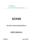
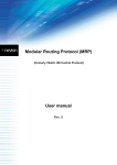
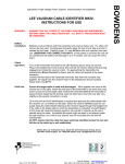
9454/9455
Installation and User Guide
Compatible Equipment
9425
9040
660
8440
Remote Keypad
Internal Sounder
Speech Communicator
4-Channel ‘Minicom’
496331 Issue 1
1 of 12
9454/5
Introduction
The 9454 and 9455 are fully programmable control units designed to meet
the requirements of larger domestic and medium commercial installations.
A basic system comprises a main control unit complete with built-in keypad,
The control unit houses the system electronics, power supply, battery and
remote signalling device (if fitted). A numeric keypad and row of indicators
(LEDs) on the outside of the unit allow the user and installer to operate the
system.
Remote keypads provide the user with the facility to set and unset the system
from strategic locations within the premises and allow the installer to program
the system. Up to TWO remote keypads may be connected to a system. The
keypads also have an optional key press PA facility.
The 9454 is a five zone system, with three ‘open collector’ type outputs.
The 9455 is a six zone system, with three single pole relay outputs.
In both systems, one output is timed (sounders) one is untimed (strobe) and
one is fully programmable. If required the 9455 can incorporate a keyswitch
for full setting and unsetting.
Technical Specification
Zones
Display
Keypads
Expansion
BS 4737
Log
Panel Siren
Extension Spkr
Battery
12 V Power
12V Aux Output
Dimensions
Weight
Comms Output
2 of 12
9454: Five plus entry/exit and PA, all closed circuit. With
individual tamper.
9455: Six plus entry/exit and PA, all FSL.
LED.
1 built-in plus up to two remote keypads (9425).
None.
Full Spec.
9454: 15 events. 9455: 15 events.
Yes.
9040. 1 max.
6.5 Ah.
9454 Quiescent Panel 50mA.
9455 quiescent panel 65mA.
9425 RKP = 40mA.
500mA.
Panel: h x w x d 163 x 257 x 72mm.
RKP: h x w x d 115 x 115 x 28mm.
Panel 1.7Kg approx.
9454: PA, Intruder, Open/Close.
9455: PA, Intruder, Open/Close.
496331 Issue 1
9454/5
Wiring
Figure 1. 9454 PCB Layout
Figure 2. 9455 PCB Layout
496331 Issue 1
3 of 12
Communicator Output Pins
9454/5
Figure 3. Wiring a Bell to the 9455.
Notes:
1. Bell O/P programmed as normally closed (SCB).
2. Link TR to0V if no external tamper is required.
3. Connect all bell wiring to the control panel with the exception of the +12V
Aux supply, until initial power-up is complete, then final connections can be
made.
4. You can fit a maximum of two 9040 16Ohm speakers to the 9455 if the
internal speaker is disconnected.
5. The SCB module shown is a typical example only. See manufacturers
instructions supplied with individual units for further information on wiring
diagrams.
Communicator Output Pins
Pin on panel
Function
Pin 1
PA
Pin2
Line Monitor Input
Pin 3
Intruder
Pin 4
Open/Close
Pin 5
+12V
Pin 6
0V
4 of 12
Colour
Red
Blue
Yellow
Black
Brown
Orange
496331 Issue 1
Pin on communicator
ST2
O/P
ST3
ST4
12V
0V
9454/5
Keypad Wiring
Notes:
1. Pins 3 and 4 are 5V positive removed in alarm to trigger.
2. Pin 2 is a 12V +ve input for Line Fault.
3. If a communicator is fitted and has an output for line fault, connecting a +ve
to the Line Monitor Input will reduce any programmed bell delay to zero and
give a visual indication on the panel LED (LF).
4. If a communicator is not fitted remove the communicator wiring harness from
the main pcb.
Keypad Wiring
Figure 4. Keypad Connection.
Notes:
1. Maximum cable distance: Daisy chain = 300m, Star Wire = 100m per leg.
2. Do not wire the extension speaker or circuit wiring within the same cable as
the remote keypad.
Programming
Initial Start Up
Before applying power to the control panel or end station, ensure that all used
circuits are connected. The control panel or end station lid switch should be
defeated or closed and NO power connections to detectors, sounders or
battery should be made at this stage.
496331 Issue 1
5 of 12
Programming Commands
9454/5
Note: If connections to the bell and AUX power are made when the system is
powered up, damage to the main pcb may occur.
1.
2.
3.
4.
Apply mains to the control panel or end station. The green “Power” and
“Day” LED will illuminate and the internal sounder will sound.
Key-in the factory default customer code “1234”. The internal sounder
will stop and the “Tamper”, “Service” and “Fault” LEDs will be flashing.
Key-in the factory default engineer code, “0” followed by “ENTER” then
“7890”. The “Fault” and ”Service” LEDs will flash and the internal
sounder will be bleeping.
Open the control panel or end station lid. The internal sounder stops
bleeping and the “Service” LED will be steady. Make connections to
AUX power, stand-by battery and connections to SAB. Proceed to
program the system.
Note: If an SAB/SCB module is fitted within the bell, it will continue to ring until the
panel supply is connected and until the bell cover lid tamper switch is closed.
Programming Commands
To change the factory default program, use the commands listed in this
section as follows:
1. Enter the command number.
2. Enter one or more digits to give the new program.
3. Press ENTER.
The panel will give a double bleep to show that it has accepted the
command. If you enter the command incorrectly the panel gives a single
tone.
Default Settings
When delivered from the factory, the panel is programmed as follows:
Zone 1, Entry Route Part Set zone.
Zone 2, Normal alarm, active in Part Set, Omit allowed.
Zone 3, Normal Alarm, active in Part Set, Omit allowed.
Zone 4, Normal Alarm, active in Part Set, Omit allowed.
Zone 5, Normal alarm.
Zone 6, (9455 only) Normal Alarm.
Zone 7(E/E) Part set.
User code 1234.
6 of 12
496331 Issue 1
9454/5
Engineering Program Commands
Engineering Program Commands
To change
Zones 1-5(6)
Key in: Followed by + ENTER
01-05(6) 0 = Not used
1 = Normal Alarm
2 = 24 Hour Alarm
3 = Entry Route
4 = 9454: Dbl knock: 9455: Fire zone
5 = 9454: Chime. 9455: Dbl knock
6 = 9454: Part set zone. 9455:Chime
7 = 9455: Part set zone
OMIT = Omit Allowed
Entry/exit zone options
07 0 = Reset to none
5 = 9454: Chime
6 = 9454: Part set zone. 9455: Chime
7 = 9455: Part set zone.
Programmable Output
11 18 = 9454: PIR set latch
29 = 9454: Shock sensor reset
19 = 9455: PIR set latch
28 = 9455: Shock sensor reset
39 = 9455: Tamper alarm function
49 = 9455: System part set
Engineer Access
20 Any 4 digit code
Bell output type
21 0 = 9454: SAB. 9455: normally open
1 = 9454: SCB. 9455: normally closed
Internal sounder
22 1 = Follows strobe
0 = Follows bell
PA
30 0 = Audible Alarm
1 = Silent Alarm
System Reset
31 0 = Customer Reset
1 = Engineer Reset
Abort facility
32 0 = Disabled
1 = Enabled
Keypad PA
33 0 = Disabled
1 = Enabled
System status
34 0 = LEDs ON
1 = LEDs OFF
Exit Mode
35 0 = Timed or Terminated
1 = Final Door Set
Control panel ET and
36 0 = Exit terminator
RKP I/P function (9455 only)
1 = Keyswitch set
Rearm
40 0 = Never
1 = Once
2 = Twice
3 = Three times
4 = Always
496331 Issue 1
Default
y
y
7890
y(9454)
y(9455)
y
y
y
y
y
y(9455)
y(9454)
y
y
y
7 of 12
Engineering Program Commands
9454/5
To change
Key in:
External sounder delay
41
Ext. sounder duration
Entry Time
Exit Time
42
43
44
CSID code
Part Set Entry/Exit
50
60
Part Set Entry Response
61
Part Set Exit Mode
62
Part Set Alarm Response
63
Engineer Log
90
8 of 12
Followed by + ENTER
0 = Nil
1 = 1.5 mins
2 = 3 mins
3 = 5 mins
4 = 10 mins
5 = 15 mins
6 = 20 mins
7 = No duration
0 = Nil
1 = 1.5 mins
2 = 3 mins
3 = 5 mins
4 = 10 mins
5 = 15 mins
6 = 20 mins
7 = No duration
0 = Continuous
1 = 10s
2 = 20s
3 = 30s
4 = 60s
5 = 90s
6 = 120s
0 = Continuous
1 = 10s
2 = 20s
3 = 30s
4 = 60s
5 = 90s
6 = 120s
nnnn (key in four digit code)
0 = As Final Exit
1 = Normal Alarm
0 = As Entry Route
1 = Start Entry Timer
0 = As Full Set
1 = 10 Second Set
2 = Instant Set
0 = Local (No comms)
1 = Full Alarm
1 see earlier events.
3 to see more recent events.
ENTER to quit log. (15 events max.)
496331 Issue 1
Default
y
y
y
y
y
y
y
y
9454/5
To change
Key in:
External Sounder
91
Strobe
92
Internal Sounder
93
Test keypad LEDs
94
Programmable output
95
Walk Test
97
Load Factory Defaults
98
Leave Engineering Mode
99
Refresh NVM
Followed by + ENTER
ENTER to stop test.
ENTER to stop test.
ENTER to stop test.
ENTER to stop test
ENTER to stop test.
ENTER to stop test.
Default
Refresh NVM (System Memory Chip)
The 9454/5 control panels have a Non Volatile Memory chip which retains all
programmed information and access codes. If the system suffers a total
power failure, the NVM will retain all information and the panel will only
require powering up and resetting. However, if the end user forgets the user
access code or the installer wants to return the panel to the factory programmed settings, continue as follows:
1. Power down the control panel, mains and battery.
2. Find the RST pins, located to the middle of the control pcb.
3. Place a small screwdriver blade to short between the “RST” pins (on the
9455 also use a short length of wire to short out the Kick Start pins).
With the blade still across the pins, power up the control panel battery
first, then Mains.
All the LEDs will flash.
4.
Remove the screwdriver blade.
The control panel loads the factory default codes.
5.
Key-in 1234, then press 0 Enter 7890. Momentarily close, then open up
control panel lid. Re-program the system.
Engineer Reset
When an engineer requires to reset the system e.g., after an alarm condition,
the control panel or end station lid does not require to be opened. Enter the
engineer code to reset the system, followed by 99.
496331 Issue 1
9 of 12
Fault Finding
9454/5
To Re-Enter Programming Mode
1.
2.
3.
Press 0 then Enter.
Key in the Engineer Access Code.
The “Fault” and “Service” LEDs flash and the internal sounder starts
bleeping.
Open the control panel lid.
The internal sounder stops bleeping and the Service LED glows steadily. The system is now in programming mode.
To Leave Programming Mode
1.
2.
Close the panel lid.
Key in 99.
Fault Finding
Under normal conditions, the “Fault”, “Service” and “Alarm” LEDs will not be
illuminated. Only the “Mains”, “Day” “Full” and “Part Set” LEDs should be
illuminated during normal use of the system. Any other LEDs which are
illuminated or flashing, signify a fault or alarm condition.
Note: The “Mains” LED will be illuminated permanently.
Any condition indicated by a combination of the “Fault”, “Service” or “Alarm”
LEDs are to be considered an abnormal condition, as shown on the opposite
page:
10 of 12
496331 Issue 1
9454/5
Fault Finding
496331 Issue 1
11 of 12
9454/5
User Commands
Full Set System
1 + ENTER + User code
Part Set System
2 + ENTER + User code
Unset/Reset System
User code
Omit zone
1 (or 2) + ENTER + User code + OMIT + zone
number (repeat OMIT + zone number for other
zones as required).
Omit 24 hr zone
OMIT + ENTER + User code + zone number (+
zone number for other zones as required)
Change User code
4 + ENTER + Old code + Old code (the system
beeps twice)+ New code (the system beeps twice)
Read Log
5 + ENTER + User code
1 to read earlier events
3 to read later events
ENTER to leave the log
Chime On/Off
7 + ENTER + User code
Bell Test
8 + ENTER + User code
Walk Test
9 + ENTER + User code
ENTER to end the test
12 of 12
496331 Issue 1