1
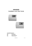
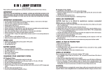
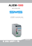
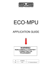
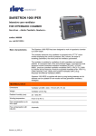
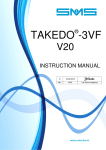
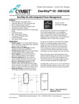
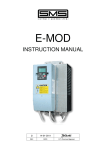
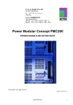
ALIEM
USER MANUAL
Draft_04
08-10-2015
D. Cavalli
REV.
DATE
Checked and Approved R. T.
PAGE INTENTIONALLY LEFT BLANK
2
ALIEM 1000 USER'S MANUAL "Draft_04" version dated 08-10-2015
1 – INTRODUCTION
ALIEM 1000 is an emergency power supply able to reproduce the THREE-PHASE voltage 400V 50/60Hz,
by using the voltage 24Vdc supplied by 2 batteries.
As an alternative to this, that its specific use, it’s possible also the SINGLE-PHASE operation (input and
output 1~230Vac), as described in Chapter 5.1.
ALIEM 1000 installation then makes possible to move the lift even in the absence of mains voltage.
During the stand-by phase, in addition to recharging the batteries, ALIEM 1000 checks their efficiency.
It is available in a single size, 1000VA (see Section 3 ).
2 - IMPORTANT SAFETY WARNINGS
Read this manual carefully before proceeding with installation or maintenance.
Safety warnings do not cover all the causes of device failure, but provide information on the most common
causes:
The following symbols appear in this document or on the equipment to warn the user on potential hazards
and require special attention.
THIS SYMBOL INDICATES AN ELECTRICAL SHOCK HAZARD.
THIS SYMBOL INDICATES TO PAY CLOSE ATTENTION .
If the device is visibly damaged, if components are missing, or if the power required is
greater than the power provided by the device, do NOT proceed with the installation.
When the device is connected to the line, it is subjected to dangerous voltages.
Installation, inspection and maintenance of the device must be performed by authorized
personnel adequately trained and must be carried out only when it is isolated from the mains
and from the batteries.
Improper installation may result in malfunction of the equipment, injury or even death.
Carefully follow the safety regulations in force
The device must be connected to the GROUND and the circuits must be protected
adequately, in accordance with the regulations in force.
To ensure the correct operation of the device and to prevent the risk of fire, use cables with
appropriate cross section in accordance with the current and the connection length.
Make sure no external object enters the device as it can lead to the malfunction of the
product or hazardous conditions when connecting to the mains or the batteries.
Make sure that the control terminals of the device are not subjected to voltage with powers
referred to the electrical network.
The control and power conductors must be carefully isolated from each other.
The examples and the diagrams contained in this manual are for demonstration purposes only.
The contents of this manual is subject to change without notice.
The manufacturer declines all liability for damages, either indirect or consequential, arising from the
use or application of the device.
ALIEM 1000 USER'S MANUAL "Draft_04" version dated 08-10-2015
3
3 – TECHNICAL SPECIFICATIONS
Rated Power
1000VA
Maximum Power Peak
1500VA
400V 50Hz
(380-10% ÷ 400 +10%)
N°2 12V 18Ah
Allowed mains voltage
Batteries
Rated current (DC)
50A (*)
Maximum rated current (DC)
75A (*)
Operating Voltage
>19V
Room temperature
<27,5V
0 ÷ 50°C
Degrees of Protection
IP20
(*) At maximum output power
3.1 – ALIEM 1000 CODE FORMAT
The code shown on the label describes some technical features that uniquely identify the product.
ALM 1000 S. 4 T 2
2 = Number of power supply batteries
T = Range available for future versions
4 = Series 400V
S = Standard Version
1000 = 1000VA
ALM = Identifier ALIEM
3.2 – PROTECTION FUSES
In order to protect the circuits connected to the network and prevent hazardous conditions in
the event of external short circuit, it is recommended to insert upstream of the power line (L1L2-L3) 3 fuses type gG with trigger current below 4A
4 – WIRING
The electrical connections to the device ALIEM 1000 must be performed by respecting the insulation and the
maximum temperatures allowed for the cables.
The Table shows the minimum cross sections referred to cable type N07V-K.
Terminals L1-L2-L3-LN - Q1-Q2-Q3-QN (Line)
1.5mm²
Terminals NN-PE-LL (Battery charger)
16mm²
Terminals 0 – 24 (Batteries)
16mm²
Terminals 24-4P-ZF-TE-BF (Control inputs/outputs)
1 mm²
Terminals NCE-CE-NOE-NOR-CR (Relay outputs)
1.5mm²
4
ALIEM 1000 USER'S MANUAL "Draft_04" version dated 08-10-2015
4.1 – CONNECTION TO THE MAINS
On the upper part of the device are fitted 8 terminals
labelled L1-L2-L3-LN-Q1-Q2-Q3-QN, through which
ALIEM 1000 is placed between the mains power supply
(input L1-L2-L3) and the primary circuit of the operating
transformer (output Q1-Q2-Q3).
Inside the device are fitted relay contacts which, during
normal operation, transfer the power of the network to the
load.
In case of main power failure, these contacts open
automatically to isolate the electrical network, and ALIEM
1000 generates a THREE-PHASE voltage with neutral on
Q1-Q2-Q3-QN, for powering the operating transformer
even in this condition.
The maximum current that can circulate on terminals L1-L2-L3-LN-Q1-Q2-Q3-QN is 4A.
Greater currents can cause hazardous conditions and damage to the device.
4.2 – CONNECTING THE BATTERY CHARGER
ALIEM 1000 comes with an internal charger, which must be supplied with a voltage of 230V 50/60Hz
( + / -10 %) on terminals LL-NN .
This power does not necessarily have to be interrupted during the emergency cycle and can, therefore, be
directly connected to the mains.
No external fuses are required, because the device is already equipped with appropriate protections.
4.3 – BATTERY CONNECTION
On the front panel are fitted the terminals 0-24 for the battery connection.
External fuses are not required, because ALIEM 1000 is equipped with appropriate protections, including
protection against connection with reversed polarity.
4.4 – CONNECTION OF CONTROL CIRCUITS
INPUTS
The controls for the inputs of ALIEM 1000 must be provided with dry contacts, referred to the 24Vdc voltage,
present on terminal 24 of the device.
Minimum operating current = 3mA.
By connecting the inputs at voltages higher than 30Vdc or with power referring to different
voltages, they may be damaged.
24
4P
24
ZF
4th POLE Input (4P) :
With active input (contact closed) the device is enabled to function.
With input inactive (contact open), the device is not enabled for operation.
The opening of the contact during the emergency operation immediately cuts off
voltage supply, bringing the device in standby condition.
EMERGENCY END input (ZF):
The input is only checked during the emergency cycle and the user can choose, via
a switch, if the end of the emergency cycle corresponds to the contact that opens
(N.C.) or that closes (N.O.).
When the "emergency end" option is inactive, the device provides the emergency
power supply continuously.
When the above option is active, ALIEM 1000 waits for a time programmable via
Dip-switch and then stops the emergency cycle, returning to stand-by mode.
ALIEM 1000 USER'S MANUAL "Draft_04" version dated 08-10-2015
5
MANUAL OPERATION (TE) input:
24
The input allows ALIEM 1000 to start an emergency cycle even in the presence
of network voltage.
When the input is active (closed contact), the emergency cycle is enabled.
When the input is inactive (open contact) the device returns to standby mode.
TE
OUTPUTS
NOE
RE
CE
NCE
NOR
RR
CR
24
BF
BF
UP
COMMON
DOWN
BF
6
RE Relay Output → EMERGENCY CYCLE IN PROGRESS
Internal dry contact:
Switching power: 250Vac / 3A – 30Vdc / 3A
The RE output is active from the beginning to the end of the emergency cycle.
It can be used to control any external breaker that isolates the network
(see Diagrams Chap.9 ).
RR Relay Output → TIMED EMERGENCY
Internal dry contact:
Switching power: 250Vac / 3A – 30Vdc / 3A
The RR output is activated with a delay of 2 seconds in relation to RE output
and is disabled 2 seconds earlier. It can be used to control any contactor that
enables motor inverter power supply, directly via ALIEM 1000 or batteries
(see Diagrams Chapter 9).
BF Output → BATTERY STATE MONITOR
ALIEM 1000 is equipped with a sophisticated system for checking the battery
efficiency.
The battery check is performed by ALIEM 1000 during the stand-by phase, if
the batteries are no longer efficient and must be replaced, output BF will be
activated. By connecting a relay between terminals BF and 24, this information
can be used for remote diagnostics.
The BF output works in a different way during the emergency phase:
at the beginning of the emergency cycle, the BF relay energizes and stays ON
until eventually the overload protection trips. In this case ALIEM 1000 cuts off
the output power, then it automatically resumes it, but in this second step the
BF relay is not energized.
So the BF relay can be used in the control panel to switch the direction
commands, in order to move the car in the opposite direction, which is
supposed to be the most favourable one.
ALIEM 1000 USER'S MANUAL "Draft_04" version dated 08-10-2015
5 – OPERATION
ALIEM 1000 detects the mains power failure (even of one phase only) and, if the contact 4P is closed,
after a few seconds it enables the emergency procedure:
- It activates the internal RE relay and cuts off the power supply which normally comes from the mains.
- After a proper delay, it activates the RR relay and then it turns on the converter, which reproduces the
supply voltage on terminals Q1-Q2-Q3-QN.
- At the activation of the external control of "Emergency End" (ZF), ALIEM 1000 waits for a programmable
time, then turns off the converter by interrupting the power supply on output terminals Q1-Q2-Q3-QN,
then disables the RR relay.
- After 2 seconds, it returns to standby mode, disabling the RE relay, and connects again the operating
transformer to the mains.
The maximum time allowed for the emergency cycle is 2 minutes.
If the overload protection trips, ALIEM 1000 will try a second starting. At the next starting, the BF output is
not activated any more, this to allow the control panel, with appropriate wiring, to make the lift to move in the
opposite direction.
A new emergency operation will only be possible after the restoration of the mains supply, and a subsequent
lack thereof.
ALIEM 1000 can also be activated via an external control, both in the presence and in the absence of
mains voltage.
5.1 – SINGLE-PHASE OPERATION VERSION
In case of single-phase mains supply 230Vac, the input voltage shall be connected to terminals L1 – LN,
while the output voltage shall be taken from terminals Q1 – QN.
6 – SETTINGS
DIP
TIPO
OFF
ON
1
Activation Delay Time
2 seconds
10 seconds
2
ZF Input Function
Opens at Floor
Closes at Floor
Shutdown Delay Time
DIP 3
OFF
ON
OFF
ON
5
Not used
/
/
6
Mains frequency
50Hz
60Hz
7
Mains Supply Type
Three-phase
Single-phase
3
4
DIP 4
OFF
OFF
ON
ON
15 seconds
10
“
5
“
0
“
ALIEM 1000 USER'S MANUAL "Draft_04" version dated 08-10-2015
7
7 – SIGNALS
MAINS voltage
present
DIAGNOSTICS
Device
powered
(24Vdc)
Blinking during battery test
Led ON = Batteries to be
replaced
Battery charger
powered
(230V 50/60Hz)
Battery polarity
REVERSED
DIAGNOSTICS
Led A
Led B
Led C
Description
Device “Ready”
Emergency Running
Car in the stop zone
High Voltage Inverter Overcurrent
Low Voltage Inverter Overcurrent
Battery Alarm
Overtemperature
Overload (Max. 4 seconds)
8 – SAFEGUARDS
♦
♦
♦
♦
♦
♦
8
Block in case of overcurrent during the emergency cycle.
Check battery efficiency.
Maximum operation time: 2 minutes.
Overtemperature.
Overload.
Battery Voltage too high or too low.
ALIEM 1000 USER'S MANUAL "Draft_04" version dated 08-10-2015
Notes
= Led OFF
= Led ON
= Led FLASHING
9 – APPLICATION DRAWINGS
ALIEM 1000 USER'S MANUAL "Draft_04" version dated 08-10-2015
9
APPLICATION DRAWING TYPE 1
Control Panel Supply and Inverter Auxiliary Supply by ALIEM 1000
Inverter Power Supply by Batteries
Use this application in case of Inverter arranged for Emergency Operation with Batteries, with Auxiliary
Supply 230Vac for the control circuit.
IMPORTANT: In this example Batteries 48V are considered.
The voltage and the capacity of the batteries depend on the type of motor used (**).
Main
Switch
R
S
T
N
PE
KL
~
~
CBAT Bat. Charger.
- +
- +
N° 2 Batteries
12V (**)Ah
24V (ALIEM)
CE
CR
-
24
4P
L1
L2
L3
LN
LL
Enable
Input
NCE
NOR
KL
KR
24
NN
0V
-
+
IE
24V
Battery Charger
Supply
Emergency End
Input
NOE
PE
+
N° 2 Batteries
12V (**)Ah
ZF
Q1
Q2
Q3
ALIEM 1000
QN
KR
IMPORTANT
The battery NEGATIVE pole
(connected to0V - ALIEM) MUST
NOT be connected to GROUND
Emergency End
Contact
+
~
*
0V (ALIEM)
Operation
Voltage
~
_
KR
L1
NOTE (*):
Filter included in the
delivery of ALIEM 1000
400
400
400
AC
AC
KL
KR
10
Line Contactor (closed in normal operation, open in emergency)
Emergency Supply Contactor
ALIEM 1000 USER'S MANUAL "Draft_04" version dated 08-10-2015
L3
Main Inverter
With Auxiliary
Supply 230Vac
in Emergency
N
Operation Transformer
L2
APPLICATION DRAWING TYPE 2
Control Panel Supply and Inverter Auxiliary Supply by ALIEM 1000
Inverter Power Supply by Batteries
Use this application in case of Inverter arranged for Emergency Operation with Batteries, with Temporary
Auxiliary Supply 230Vac on L1-L2 for the control circuit (for example, VACON V20).
IMPORTANT: In this example Batteries 96V are considered.
The voltage and the capacity of the batteries depend on the type of motor used (**).
Main
switch
R
S
T
N
PE
KL
~
~
CBAT Bat. Charger
- + - +
~
~
CBAT Bat. Charger
-
+
-
+
N° 2 Batteries
12V (**)Ah
24V (ALIEM)
-
+
-
+
-
+
-
+
N° 6 Batteries
12V (**)Ah
IE
CE
CR
24
4P
L1
L2
L3
LN
Enable
input
LL
NOR
KL
KR
24
0V
NN
24V
Battery Charger
Supply
Emergency End
Input
NCE
PE
ZF
Q1
Q2
Q3
ALIEM 1000
QN
KR
NOTE (*):
Filter included in the
delivery of ALIEM 1000
Emergency End
Contact
0V (ALIEM)
~
Operation
Voltage
TRE
+
~
*
_
KR
L1
400
400
400
L2
L3
N
IMPORTANT
The battery NEGATIVE pole
(connected to0V - ALIEM) MUST
NOT be connected to GROUND
Main Inverter
Operation Transformer
KL
KR
TRE
Line Contactor (closed in normal operation, open in emergency)
Emergency Supply Contactor
Timer to switch off the auxiliary supply after 3-5sec.(before the inverter switches on the power output)
ALIEM 1000 USER'S MANUAL "Draft_04" version dated 08-10-2015
11
APPLICATION DRAWING TYPE 3
Control Panel and Main Inverter Supply by ALIEM 1000
Use this application in case of geared lift system with asynchronous motor MAX 4kW or in case of gearless
lift system with inverter provided with “Battery Saving” option.
Main
Switch
R
S
T
N
N° 2 Batteries
12V 18Ah
PE
-
+
KL
24V (ALIEM)
CE
CR
24
4P
L1
L2
L3
LN
LL
Enable
Input
Emergency End
Input
NCE
NOR
KL
KR
24
PE
NN
0V
24V
Battery Charger
Supply
ZF
Q1
Q2
Q3
QN
ALIEM 1000
+
~
Emregency End
Contact
~
*
_
KR
0V (ALIEM)
NOTE (*):
Filter included in the
delivery of ALIEM 1000
Operation
Voltage
400
400
400
N
L1
L2
L3
Main Inverter
Operation Transformer
KL
KR
12
Line Contactor (closed in normal operation, open in emergency)
Emergency Supply Contactor
ALIEM 1000 USER'S MANUAL "Draft_04" version dated 08-10-2015
10 – TROUBLESHOOTING
IN PREPARATION
11 – DIMENSIONS AND WEIGHT
CLAMP FOR DIN RAIL MOUNTING (din46277)
- WEIGHT about 2kg
For further clarifications and suggestions please contact:
SMS SISTEMI e MICROSISTEMI s.r.l. (SASSI HOLDING group)
Via Guido Rossa, 46/48/50 Loc. Crespellano 40053 Valsamoggia BO - ITALY
Phone: +39 051 969037 Fax : +39 051 969303 Technical Support: +39 051 6720710
E-mail: [email protected] website : www.sms-lift.com
ALIEM 1000 USER'S MANUAL "Draft_04" version dated 08-10-2015
13