1
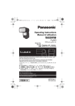
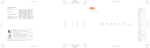
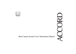
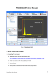
L5BG2_XE(VCC-4795P)(ENGLISH).fm
English
Deutsch
1 ページ 2006年12月20日 水曜日 午前11時6分
Français
DIMENSIONS (Unit: mm)
3
INSTRUCTION MANUAL
67
PRECAUTIONS
136
127
1
VCC-4795P
54
■ In case of a problem
■ Protect from high temperatures
Do not use the unit if smoke or a strange odor comes from the unit,
or if it seems not to function correctly. Turn off the power
immediately and disconnect the power cord, and then consult your
dealer or an Authorized Sanyo Service Center.
Do not install close to stoves, or other heat sources, such as
spotlights, etc., or where it could be subject to direct sunlight, as this
could cause deformation, discoloration or other damages.
Be careful when installing close to the ceiling, in a kitchen or boiler
room, as the temperature may rise to high levels.
■ Do not open or modify
Color CCD Camera
11
15.4
24.4
28
1/4”-20 UNC
Do not open the cabinet, as it may be dangerous and cause damage
to the unit. For repairs, consult your dealer or an Authorized Sanyo
Service Center.
■ Do not put objects inside the unit
Make sure that no metal objects or flammable substance get inside
the unit. If used with a foreign object inside, it could cause a fire, a
short-circuit or damage. Be careful to protect the unit from rain, sea
water, etc. If water or liquid gets inside the unit, turn off the power
immediately and disconnect the power cord, and then consult your
dealer or an Authorized Sanyo Service Center.
■ Be careful when handling the unit
■ Cleaning
• Dirt can be removed from the cabinet by wiping it with a soft cloth.
To remove stains, wipe with a soft cloth moistened with a soft
detergent solution and wrung dry, then dry by wiping with a soft
cloth.
• Do not use benzine, thinner or other chemical products on the
cabinet, as this may cause deformation and paint peeling. Before
using a chemical cloth, make sure to read all accompanying
instructions. Make sure that no plastic or rubber material comes
into contact with the cabinet for a long period of time, as this may
cause damage or paint peeling.
To prevent damage, do not drop the unit or subject it to strong shock
or vibration.
■ Do not install this unit close to magnetic fields
The magnetic fields may result in unstable operation.
About this manual
■ Protect from humidity and dust
Before installing and using the camera, please read this manual carefully.
Be sure to keep it handy for later reference.
To prevent damage, do not install the unit where there is greasy
smoke or steam, where the humidity may get too high, or where
there is a lot of dust.
Depending on the conditions of use, installation and environment,
please be sure to make the appropriate settings and adjustments.
If you need help with installation and/or settings, please consult
your dealer or an Authorized Sanyo Service Center.
CONNECTION EXAMPLE
Monitor display
Monitoring
SPECIFICATIONS
Video output
Video S/N ratio
Backlight compensation
White balance
Gain control
Light control
Lens mount
Flange back
Electronic shutter
Aperture compensation
Sync system
Day/Night mode
Operating Environment
[Monitoring/Recording system]
Recording
1AC6P1P2970-L5BG2/XE (0705KP-SY)a
Scanning system
Image sensor
Number of effective pixels
Horizontal resolution
Minimum illumination
(approx.)
[Monitoring system]
Monitoring
Printed on recycled paper
Digital Video Recorder
Monitor display
Power supply
Power consumption
(approx.)
Weight (approx.)
:
:
:
:
PAL standard 625 lines, 50 fields/sec.
1/3" interline transfer method CCD
752 (H) x 582 (V)
More than 520 TV lines
: Gain high: 0.01 lx (F 1.2, B/W mode),
0.45 lx (F1.2, color mode)
Gain normal: 0.02 lx (F 1.2, B/W mode),
0.6 lx (F1.2, color mode)
: 1.0 V(p-p)/75 Ω, composite, BNC
: More than 48 dB (AGC off: More than 50 dB)
: OFF, Multi-spot metering (High/Normal), Center zone
metering
: ATW/Manual
: Normal/High
: Optical auto iris lens/Electronic iris (indoor use)
: CS mount
: 12.5 mm ± 0.5 mm adjustment
: 1/50, 1/120, 1/500, 1/1000, 1/2000, 1/4000, 1/10000 sec.
: Sharp/Normal
: Internal sync/Line lock
: Auto (High/Low), Manual (at CONTROL terminal)
: Temperature: –10°C – +50°C (14°F – 122°F)
Humidity: less than 90 % RH (no condensation)
: 24 V AC ±10%, 50 Hz/ 12 – 15 V DC
: 3.7 W (with auto-iris lens)
: 400 g (without lens)
Appearance and specifications are subject to change without prior notice
or obligations.
TROUBLESHOOTING
Before sending the camera out for repair, check the items below.
If the problem persists after checking these items, consult your
dealer or an Authorized Sanyo Service Center.
■ If no image appears
• Is the coaxial cable attached securely?
• Are the power and voltage normal?
• Has the iris of the lens been adjusted correctly (with the LEVEL
dial)?
• Is there adequate illumination?
■ If the image is unclear
•
•
•
•
Is the monitor adjusted correctly?
Is the flange-back position correctly set?
Is the lens in focus?
Is the lens clean?
Dirt or fingerprints on the lens can adversely affect the image.
Gently wipe any dirt or fingerprints off the lens with a soft cloth or
lens cleaning paper and cleaning fluid (commercially available).
SERVICE
The camera is a precision instrument. Handle it carefully and always
follow the safety precautions. If the camera requires service, never
try to repair it yourself or open the casing.
For servicing, maintenance, or repairs, consult your dealer or an
Authorized Sanyo Service Center.
SANYO Electric Co., Ltd.
Printed in Japan
Please note:
Your SANYO product is designed and
manufactured with high quality materials and
components which can be recycled and
reused.
This symbol means that electrical and
electronic equipment, at their end-of-life,
should be disposed of separately from your
household waste.
Please dispose of this equipment at your local
community waste collection/recycling centre.
In the European Union there are separate
collection systems for used electrical and
electronic products.
Please help us to conserve the environment
we live in!
This symbol mark and recycle system
are applied only to EU countries and
not applied to countries in other areas
of the world.
L5BG2_XE(VCC-4795P)(ENGLISH).fm
2 ページ 2006年12月20日 水曜日 午前11時6分
Français
Deutsch
English
CONNECTIONS AND ADJUSTMENTS
b Attaching the lens
b Camera attachment
b Flange-back adjustment
Use any DC type and CS mounting lens equipped with an auto iris (sold separately).
When attaching the camera, make sure to verify that the attachment surface will allow full
tightening of the screws. Plaster board, etc., may not give a strong enough attachment, and
it is recommended to use a reinforcement, or other method so that the screws are anchored
securely.
This normally does not need adjustment. If the picture is out of focus at the telephoto position,
adjust the flange-back position as described below.
1
2
3
• When monitoring lighting or other extremely bright objects
(which exceed the maximum required illumination),
smearing may occur in the vertical or horizontal direction
(either above and below the high-brightness object or as a
perpendicular band). In such a case, adjust the angle of
illumination and other factors while observing the monitor.
5 mm max.
• Depending on the type of the lens, the shape of
the lens plug may differ. In this case, consult your
dealer or an Authorized Sanyo Service Center.
• Apply adapter ring (sold separately) when you use
any C mounting lens.
Pin layout for LENS terminal
Brake coil (–)
Drive coil (+)
Brake coil (+)
Drive coil (–)
POWER VIDEO
OUT
CONTROL
LINE
PHASE
CBG
GND
AC24V
DC12V
b Supported coaxial cables
Tighten.
A Bracket screws (longer)
b Camera adjustments/settings
3 Day/Night function switchover point
6 Backlight compensation
The camera comes pre-adjusted and ready to install at the time of
factory shipment, but you can make adjustments or settings if you
need.
This switch is used to set the timing for automatic switching
between color and black-and-white images.
Only when using an auto-iris lens
If you have trouble adjusting the camera, consult your dealer or an
Authorized Sanyo Service Center.
H
H
S
M
C MWB LL
a Set the switchover point to brighter side so that the automatic
switch may trip in brighter condition for switchover between color
and black-and-white images.
B/W
1
4
5
6
7
8
LSB L
N
N
2
MSB
3
OFF ATW INT
RED
L
H
LEVEL
A. I.
LENS
BLUE
Only when using a manual or fixed iris lens (EI)
<DC 12 V connection>
1
2
3
• Set the lens aperture to the shortest F-stop.
• When using a manual or fixed iris lens under fluorescent light, the
image may flicker.
DC12V
2 Electronic shutter speed setting
(unit: second)
Check that polarity is correct.
1/50
1/120
1/500
1/1000
Color
Switchover point
4
9
1 EI setting (for indoor use)
GND AC24V
B/W
Low
Multi-spot metering
Backlight compensation
to the entire screen*
High
a Set the switchover point to darker side so that the automatic switch
may trip in darker condition for switchover between color and
black-and-white images.
9 10
ES/EI C-BW
AP BLC WB SYNC
GAIN
Color
Switchover point
4
12 3 4 5 6 7 8
To prevent a fire hazard use any
UL listed wire rated VW-1.
Loosen.
B
• When using an RG-59U (3C-2V) cable, do not use it
on piping or air wiring.
b Power cable
7
Normal
8
7
1
Under near infrared lighting or other similar conditions, hunting reaction may occur because the
Day/Night function is not carried out normally. In such case, refer to the following diagram for cable
connection to fix the image either to color or black-and-white by using an external switch, etc.
CONTROL terminal
(F indicates a connection point.)
B/W
Color
Day/Night
function*
C
(Color)
–
F
–
F
B
(B/W)
F
–
–
F
G
(Ground)
F
F
–
F
C B G
AWG24:
600 m max.
* You can control the timing for automatic switchover between color and black-and-white images by using the
C-BW switch. (Refer to “3 Day/Night function switchover point”.)
You cannot control the switchover operation by using an external switch, etc., while switching between
color and black-and-white images is actually in progress by the DAY/NIGHT function.
3
1/2000
1
2
3
1/4000
1
2
3
1
2
4 Auto gain control (AGC)
High sensitivity
Increased electronic sensitivity to obtain a
bright image in a lower illuminance*
Normal
sensitivity
5
5
3
1/10000
2
3
1
2
3
1
2
3
• Using the high speed electronic shutter indoors with low lighting,
will give darker pictures. In such a case, add some lights to make
sure the lighting is sufficient.
• If the lighting is very bright, pay attention to the light angle in order
to avoid or minimize the smear phenomenon effect.
• If the entire image is too dark or too bright, refer to the “9 Lens
iris level adjustment”
8
7
OFF
7
8
8
7 White balance (color compensation)
• The color image will be displayed first when the power is turned on.
• When switching between color and black-and-white images
automatically, it is normal for movement of the optical filter to be
heard and for a vertical black band to move across the screen.
• Switching from black-and-white to color may occur if there is a
significant degree of reflection from the object when using infrared
illumination in black-and-white image. Adjust the illumination to
avoid switching to color image.
• The focus setting position may differ between color and
black-and-white images. Carry out adjustment to ensure that the
focus for both images is in the optimum position.
* This setting causes noise generation and a grainy image.
5 Aperture compensation
1
CONTROL
2
Center zone metering
Backlight compensation
to the central portion of
the screen
* If the background of the object is extremely dark, set to Center zone
metering.
Sharp outline
Normal outline
6
6
Auto-Tracing
White balance
Manual White Balance
Turn clockwise to
augment the color.
9
9
RED
BLUE
8 Sync setting
Line-Lock
(Only when using an AC power supply)
Synchronizes the unit with power
frequency*
Internal sync
LINE
PHASE
10
b CONTROL terminal connection
Set to the maximum
telephoto position and
focus the picture.
Repeat steps 2 and 3 until the image stays in-focus when changing from a wide-angle position to
a telephoto position.
ON
• If you use a cable other than the type above, the
image or sync signal will be attenuated and will not be
transmitted correctly.
2
Set to the maximum
wide-angle position
and focus the picture.
1
4
High
Cable type – Length: RG-59U (3C-2V) – 250 m max.,
RG-6U (5C-2V) – 500 m max., RG-11U (7C-2V) – 600 m max.
<AC 24 V connection>
A
• You can change the bracket topside down. Make sure to
use the longer screws A to secure the bracket.
LINE PHASE
dial
POWER lamp
3
B Camera screws (shorter)
10
(Rear panel)
* Adjust the roll by turning the LINE PHASE dial on the second and
subsequent cameras.
If the vertical roll cannot be corrected by adjusting the LINE PHASE
dial on the second and subsequent cameras, try adjusting the LINE
PHASE dial on the first camera. If it still cannot be corrected, please
check that the polarity of the power cords of all connected devices is
correct.
9 Lens iris level adjustment
When using an auto-iris lens, if the entire image is too dark or too
bright, adjust the contrast.
Low (darker)
High (brighter)
L
H
LEVEL
A. I.
LENS