1
Operating instructions
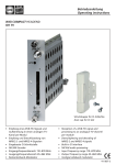
VS 21
Multi channel programmable Filter-Amplifier
GB
Operation LED
Handset OK 41A
For digital and analogue channels
6 inputs: B I-II / B III / VHF-UHF and 3 UHF inputs split over 10 UHF programmable clusters
Each cluster with 1 to 7 channels bandwidth
All settings by WISI handset OK 41 / OK 41A
COPY function permits transfer of all settings from one unit to another
OK41A handset with memory function for saving up to 10 settings to copy them to another unit
Highly selective filters
Low noise figure and high gain split band amplifiers
High output level of 123 dBµV
Automatic levelling of signal or manual via 30 dB attenuator
Selectable remote power on VHF-UHF and UHF inputs
-30 dB test output
- 13 -
Index
Page
Safety and installation notes
Mounting - Dimensions
Operation with handset OK 41 / OK 41A
- Menu structure
Main menu
Attenuator settings
Cluster programming
- Setting Start and Stop channels
- Single channel mode
- Switching off a cluster
- Overlapping cluster
GB
Page
15
15
16
17
18
19
19
20
20
20
20
Setting inputs
General attenuator UHF
Automatic level adjustment
Copy function with OK 41A
General Reset
Block diagram
Specifications
Operating principle
8+)
%,,,
FK FK
FK
FK FK
I
I
8+)
)0
FK
FK FK I
8+)
0+]
I
FK FK
8+)
8+)
9+)8+)
8+)
%,,,
%,,,
6HWWLQJV
&OXVWHU
2XW
6WDUW&KDQ 6WRS&KDQ &OXVWHU
6WDUW&KDQ 6WRS&KDQ &OXVWHU
6WDUW&KDQ 6WRS&KDQ 6WDUW&KDQ 6WRS&KDQ &OXVWHU
96
0XOWL&KDQQHO
3URJUDPPDEOH)LOWHU$PSOLILHU
I
&OXVWHU 6WDUW&KDQ 6WRS&KDQ 6HOHFW,QSXW8+)&O
8VH$XWR/HYHOIXQFWLRQIRUDOO8+)
LQSXWV
96LVOHYHOOLQJDOO8+)FKDQQHOVWR
G%9RXWSXWOHYHO JHQHUDO
DWWHQXDWRULVVHWWRG%
73G%
8VH%,,,DQG%,,,DWWHQXDWRUIRUWKH
RWKHUVLJQDOV
)0
- 14 -
FK FK
FK
FK
FK
FK FK
FK
FK
FK
I
21
21
21
21
22
22
23
Safety and installation notes – please observe!
Caution
The mains voltage must match the rated input
voltage of the unit (230 VAC).
Connecting cable — Lay the cable so that noone can trip over it.
— Lay the cable with a
downward loop so that any water condensing
on it can drip on the floor instead of running
into the unit.
Selecting the installation location
Excessive temperatures will reduce the operating
lifetime of the unit. Do not install the unit directly
above or in the vicinity of radiators or heating
systems where it would be subjected to thermal
radiation or oil vapours.
Caution – danger!
In accordance with EN 50 083-1, the antenna
system must comply with the safety requirements
with respect to grounding, potential
equalisation, etc.
Service work
Service work may be carried out only by qualified
personnel. Always disconnect the supply voltage
before starting any such work.
Important
This amplifier is equiped with a fan on the back
side to improve cooling capacity. Leave a
minimum space of 15cm around to the product
to guarantee a maximum of ventilation.
Cleaning
Only use a dry soft cloth to clean the cabinet. Do
not use solvent
Moisture
Water dripping or splashing onto the unit will
damage it. If there is condensation on the unit,
wait until this has evaporated before switching
the unit on.
Mounting — Dimensions
1. Ground
2. Place the adapter into the holder
3. Connect the power supply to the
amplifier
4. Plug the mains cable to the
adaptor. LED (6) illuminates.
5. Click the adapter holder to the
amplifier
(6)
- 15 -
GB
Operation with handset OK 41 / OK 41A
Handset OK 41 / OK 41A
(Accessory)
WI S I
VS 2 1 V2 . 7
Standby
Plug the handset into the socket.
Connect power supply voltage to basic unit.
The software version (e.g. „V 2.7") is displayed.
Press any key to call the module menu.
Main menu
Up
GB
Right
Left
Down
keys
— Select parameters
key
— Move to parameter menu.
key
— Back.
Parameter menu
keys
— Select parameter.
key
— Move to parameter sub-menu.
key
— Back.
Parameter sub-menu
OK 41A = (Accessory)
keys
— Back
keys
— Change the value, e.g. change 52 to
62.
- Saving data: data are saved automatically.
- 16 -
Menu structure
WISI VS 21
v2.7
Parameter Submenu
Main Menu
Parameter-Menu
Band I -II
20 dB
Attenuator
0 dB
I -II
Band III
20 dB
Attenuator
20 dB
III
Band VHF /UHF
20 dB
Attenuator V /UHF
20 dB
Cluster 1 (UHF 1)
30 dB Ch .52-54
Start Chan . CL.1
Stop Chan
Attenuator
Start Chan . CL.1
Channel 52
Stop Chan . CL.1
Channel 52-54
Attenuator
30 dB
Cluster 8 (UHF 2)
30 dB Ch .52-54
Start Chan . CL.8
Stop Chan
Attenuator
Select Input
Start Chan . CL.8
Channel 52
Stop Chan . CL.8
Channel 52-54
Attenuator
30 dB
General Att . UHF
10 dB
Auto Level
Attenuator G .UHF
10 dB
CL.8
Select Input
UHF3: Cluster 10
CL. 1 xxxxxxxxxx
parked cluster
Auto Level
Show Last Result
Start AGC !
Data Import
CL.1
Auto Level .....
CL. 1 2 /30
DataImport
Import
Data
RS-232
RS-232Interface
Interface
VS21 Position
1
VS21 Position
2
Load Defaults
Data Store
Data Store
VS 21 Position
1
VS 21 Position
VS 21 Position
1
2
- 17 -
GB
Main Menu
Press
to enter the "Main Menu". Press
again to enter the "Parameter-Menu".
Main Menu
WISI VS 21
v2.7
Band I -II
20 dB
Band III
20 dB
Band VHF /UHF
20 dB
GB
Cluster 1 (UHF 1)
30 dB Ch .52-54
Cluster 10 (UHF 2)
30 dB Ch .52-54
General Att . UHF
10 dB
Auto Level
Data Import
Data Store
- 18 -
Attenuator settings
Enter with
the "Parameter Submenu" and change the attenuation with
Band I -II
20 dB
Attenuator
20 dB
buttons.
I -II
Cluster programming
The amplifier consists of 3 UHF inputs. They are splitted into 10 clusters.
A cluster is a group of channels consisting of max. 7 channels.
Choose the combination by yourself with setting "Start" and "Stop"
channels.
channels
1 2 3 4 5 6 7
GB
channels
1 2 3 4 5 6 7
channels
1 2 3 4 5 6 7
channels
1 2 3 4 5 6 7
Setting Start and Stop channels
button.
1. Select one of the cluster 1...10 and press
2. First select "Start Channel" and set the Start channel.
3. Press .
4. Select "Stop Channel" and set the "Stop channel".
Start Chan . CL.8
Stop Chan
Attenuator
Example
Start
Start Chan . CL.8
Channel 52
Stop Chan . CL.8
Channel 52-55
Attenuator
30 dB
Stop
Cluster
(8)
channel
52
55
CL.8
- 19 -
Single channel mode
Note:
Setting the "Start channel" (example ch 33)
also sets the "Stop channel" autom. to ch 33.
Overlapping
Switching off a cluster
- Select "Start" channel and set to OFF.
The "Stop" channel"is set autom. to OFF.
22
Overlapping cluster
- * The digit displays overlapping.
29
24 25
5. Attenuator
- Set the attenuator 0-30 dB for each cluster.
GB
Setting cluster inputs
The 3 UHF inputs of the amplifier are splitted
into 10 clusters.
The input can only be configured for
cluster 8, 9, and 10.
Select the "Parameter-Submenu" and
configure the inputs.
Start Chan . CL.8
Stop Chan
Attenuator
Select Input
Start Chan . CL.8
Channel 52
Stop Chan . CL.8
Channel 52-54
Attenuator
30 dB
CL.8
Select Input
UHF3: Cluster 10
Note:
Cluster 1 and 2 are assigned to UHF 1.
Cluster3, 4, 5, 6 and 7 are assigned to UHF 2
Cluster 8, 9 and 10 are assigned to UHF 2 or 3.
Each cluster can be set to OFF. For example:
only one cluster is needed for UHF 2 switch
OFF the other clusters.
- 20 -
UHF 1
2
UHF 2
8
UHF 3
0
2
2
7
5
1
3
channel
General attenuator UHF
Select in the "Main Menu" - "General Att. UHF" and press
again to enter the "ParameterMenu". All input levels can be set. The default setting for this attenuation is 11 dB.
General Att . UHF
11 dB
Attenuator G .UHF
11 dB
Automatic level adjustment
1. First select the START and STOP channels
for each cluster.
2. Set the clusters to OFF which are not in use.
3. Start "AGC".
4. The amplifier starts levelling automatically
the clusters.
This procedure will take about 1 to 2 minutes,
depending on the number of channels and
clusters to be equalized.
5. The amplifier displays the results in the
parameter sub-menu:
CL. 1
XXXX I XXX I XI
cluster 1
parked cluster
cluster 5
signal weak
Note:
The automatic level adjustment set the output
level of the clusters at 100 dBµV (for an input
level between 50 to 80 dBµV).
The general attenuator is fixed to 11 dB after
the automatic level adjustment. It can be
adjusted from 0 to +20 dB to get a level
between 90 to 110 dBµV (see "General Att.
UHF ).
The difference between analog and digital
signals is very small. You can correct this after
automatic levelling has finished.
cluster 9
signal strong
Copy function with OK 41A (Accessory)
The data import function allows to store settings from the OK 41A handset or from another VS 21.
The OK 41A consists of 10 "Memories". Select one of the OK 41A memory ("Position1...10").
Select "Data import" to store the datas from master and restore to the -Unit to be set- with "Data
Store"
- 21 -
GB
General Reset
Select "Data import" and "Load default".
Block diagram
GB
- 22 -
Specifications
GB
/ 14W
WILHELM SIHN JR. GmbH & Co. KG
Empfangs- und Verteiltechnik
P.O. BOX 1220, 75219 Niefern-Oeschelbronn, Germany
Phone +49 7233 66 280, Fax - 66 350,
E-mail: [email protected] / Internet: http://www.wisi.de
... a link to the future
10/05
Technical modifications reserved
- 23 -
GB
- 24 -