1
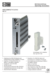
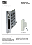
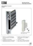
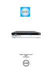
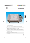
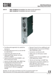
Betriebsanleitung Operating instructions WISI COMPACT HEADEND OH 76 F • • • • • Empfang eines DVB-S-Signals und Aufbereitung in einen analogen TV-Kanal Empfang und Entschlüsselung von MPEG-2-Signalen Eingangsfrequenzbereich 950–2150 MHz Ausgangsfrequenzbereich 45–862 MHz Restseitenband-Modulator • • • • • Reception of a DVB-S signal and processing to an analog-TV-channel Demultiplexing and decoding of MPEG-2 signals Input frequency range 950–2150 MHz Output frequency range 45–862 MHz Vestigial sideband modulator 412 278 a Headend OH 41 (OK 41 A) (Zubehör) / Headend OH 41 (OK 41 A) (Accessory) WI S I OH 5 0 HEADEND V1 . 0 0 Up Right Left Down Hinweis: Nach erfolgter Programmierung ziehen Sie das Handset ab. Note: After programming disconnect the handset. Stand by Betriebsspannung am Grundgerät angeschlossen und „Initialisierung der Module“ abgeschlossen. Handset an Buchse des Grundgerätes einstecken. Durch Drücken einer Taste gelangt man in das Modul- oder System-Menü. Stand by Supply voltage connected to basic unit and wait till mode “Initialising the modules” has finished. Plug the handset into the socket on the basic unit. Press any key to call the module menu or System menu. Modul-Menü / Module menu Modul 1 OH 76 F / Module 1 OH 76 F Parameter-Menü / Parameter menu Modul 2 OH 85 / Module 2 OH 85 DiSEqC Sat-IF Parameter-Untermenü / Parameter sub-menu 1894 Modul 14 OH 88 H / Module 14 OH 88 H Modul-Menü / Modul menu ▲▼ Tasten / keys — Modul 1… 14 wählen / Select module 1...14 ▶ Taste / keys — Weiter zum Parameter-Menü / Move to parameter sub-menu ◀ Taste / keys — Zurück / Back -2- Headend OH 41 (OK 41 A) (Zubehör) / Headend OH 41 (OK 41 A) (Accessory) Parameter-Menü / Parameter menu ▲▼ Tasten / keys — Parameter wählen / Select parameter ▶ Taste / keys — Weiter zum Parameter-Untermenü / Move to parameter sub-menu ◀ Taste / keys — Zurück / Back Parameter-Untermenü / Parameter sub-menu ◀▶ Tasten / keys — Zu ändernde Stelle wählen Cursor blinkt unter der Stelle z.B. 1894 Bei Überschreiten des dargestellten Zahlenbereiches, zurück zum Parameter-Menü Select the digit to be changed Cursor blinks below the digit, e.g. 1894 If the permissible range is exceeded, the unit returns to the parameter menu ▲▼ Tasten / keys — Wert ändern z.B. 1894 in 1834 Change the value, e.g. change 1894 to 1834 Speichern / Saving data Autom. nach Verlassen des Parametermenüs oder ca. 60 Sekunden nach der letzten Eingabe. Data are saved automatically after leaving the parameter, or 60 seconds after the last entry. Front-LED / Front LED indication rot/red kein Eingangssignal / no input signal grün/green Eingangssignal wird dekodiert / decoding input signal Front Klinkenbuchse 3,5 mm (A/V) / Front A/V connector 3.5 mm Audio-Links / audio left Video (1 Vss / 75 Ω) GND für Audio + Video / GND for audio + video Audio-Rechts / audio right -3- Bedienung / Instructions DiSEqC Eingangsebenenwahl LNB off ........................keine LNB-Speisung SAT1-SAT16 . ................Ebenenwahl mit DiSEqC-Protokoll LNB DC . ......................nur LNB-DC-Speisung Level Selection LNB off ........................no LNB feeding SAT1-SAT16 . ................level selection with Diseq protocol LNB DC ........................only dc-feeding for the LNB Sat-IF SymRate 950–2150 MHz Eingangsfrequenzwahl Eingangsfrequenz des gewählten Kanal-Tuners 950–2150 MHz Input frequency selection input frequency of the tuner of the selected channel Eingangssymbolrate 1000–45000 kSym/s Symbolrate des gewählten Kanal-Tuners 1000–45000 kSym/s Sat-Lev Input symbol rate symbol rate of the tuner of the selected channel Eingangspegel des empfangenen SAT-Signals in dBμVPegel des dekodierten Eingangsignals Dekodierung ist im Bereich von ca. 40–80 dBµV möglich. Input level of the satellite signal at the input in dBμVLevel of the decoded input signal Decoding works in the range between 40 to 80 dBµV Sat-CNR Sat-BER -4- Signal/Rauschabstand Eingangssignal in dB in dB Signal to noise ratio of the input signal <1.00e-7 Bitfehlerrate Eingangssignal Bitfehlerrate des dekodierten Signales <1.00e-7 Bit error rate of the input signal Bit error rate of the input signal Bedienung / Instructions Program Programmauswahl 1 Das Erste _T ..........Pgm.-Name; ‚_‘ = FTA; T = TV 2 zdf_neo _T* ........Pgm.-Name; ‚_‘ = FTA; T = TV; ‚*‘ = ausgewählt 3 NDR Kultur _R . ........Pgm.-Name; ‚_‘ = FTA; R = Radio Programme selection 1 Das Erste _T ..........Pgm.-Name; ‚_‘ = FTA; T = TV 2 zdf_neo _T* ........Pgm.-Name; ‚_‘ = FTA; T = TV; ‚*‘ = selected 3 NDR Kultur _R .........Pgm.-Name; ‚_‘ = FTA; R = Radio Die Darstellung dient nur als Beispiel und ist aus verschiedenen Programmströmen zusammengefügt. Hier werden die vorhandenen Services dargestellt. Der Service wird mit einer laufenden Nummer dargestellt, dann folgt der Service-Name. Die Zeichen „_“ oder „#“ zeigen den Verschlüsselungsstatus des Eingangssignales an: „_“ steht für FTA (free to air) nicht verschlüsselt und „#“ steht für einen verschlüsselten Service. Das nächste Zeichen gibt den Servcie-Typ an „T“ = TV, „R“ = Radio. Ein Service kann durch verlassen des Untermenüs ausgewählt werden. Der Service wird daraufhin eingestellt, erkennbar durch den sich drehenden Balken rechts. The following description only serves as an example, which is combined from services of different transponders. It displays the available services. The services are represented with a consecutive number, followed by the service name. The symbol “_” or “#” are showing the status of the Decryption: “_” stands for FTA (free to air), and “#” stands for an encrypted service. The next symbol shows the type of service: “T” for TV, “R” for radio. A service can be selected by leaving the sub menu. The service will then be tuned. While this is happening you will see the “active” bar turning on the right side of the display. PgmLang Programmauswahl deuStehen bei einem Service mehrere Sprachen zur Verfügung, so werden diese hier dargestellt und es kann eine ausgewählt werden Programme selection deuIf multiple languages are available, one of the displayed can be selected. -5- Bedienung / Instructions F-Out Out-Att Zoom 471,25 Ausgangsfrequenz 45,00–862,00 in 0,25 MHz 471,25 Output frequncy 45,00–862,00 in 0,25 MHz 5 dB Ausgangsdämpfungssteller 0–15 dB in 1-dB-Schritten 5 dB Output attenuator 0–15 dB in 1-dB-steps Bildausgabeformat 4:3 Box.........................Bildformat 4:3 in Letterbox 16:9..............................Bildformat 16:9 4:3 Pan.........................Bildformat 4:3 pan scan Aspect ratio format 4:3 Box.........................Aspect ratio 4:3 in Letterbox 16:9..............................Aspect ratio 16:9 4:3 Pan.........................Aspect ratio 4:3 pan scan VPSMode Video Programming System Modus off................................keine Übertragung der VPS-Info EIT................................VPS-Info aus EIT wird eingefügt TTX..............................VPS-Info aus Teletext wird eingefügt Video programming system info mode off................................no distribution of VPS info EIT................................VPS info from EIT will be inserted TTX..............................VPS info from teletext will be inserted SubMode Untertitel-Modus teletext.........................Untertitel aus Teletext DVB..............................Untertitel aus DVB-TS-Daten Sub title mode teletext.........................Sub title from teletext DVB..............................Sub title from DVB-TS data SubLang Untertitel-Sprache off................................keine Untertitel DVB..............................Untertitel aus DVB-TS-Daten Sub title language off................................No sub title DVB..............................Sub title from DVB-TS data -6- Bedienung / Instructions Bor.Up* Videosignalausgabe Rand oben 0..................................Startzeile für ausgegebenes Videosignal Video signal output border up 0..................................Start line for displayed video signal Bor.Dwn* Videosignalausgabe Rand unten 576...............................Endzeile für ausgegebenes Videosignal Video signal output border down 576...............................End line for displayed video signal Bor.Lft* Videosignalausgabe Rand links 0..................................Startpixel auf der linken Seite des Videosignales Video signal output border left 0..................................Start pixel for displayed video signal Bor.Rgh* Videosignalausgabe Rand rechts 720...............................Endpixel auf der rechten Seite des Videosignales Video signal output border right 720...............................End pixel for displayed video signal VidNorm PAL NTSC-M SECAM Video Norm des Ausgangsignals PAL NTSC-M SECAM Video standard of the output signal * Werden die voreingestellten Boarder-Werte verändert, so wird automatisch der Teletext ausgeblendet. If the boarder values are changed the tele text will be surpressed. -7- Bedienung / Instructions TV-Std TV-Standard des generierten Ausgangssignals B/G...............................alle Audiosignalarten sind zulässig D/K...............................alle Audiosignalarten sind zulässig I....................................Audiosignal stereo oder dual wird auf mono umgestellt L...................................wie bei I M.................................wie bei I TV standard of the generated output signal B/G...............................any audio signal is permitted D/K...............................any audio signal is permitted I....................................stereo or dual tone will be changed to mono L...................................stereo or dual tone will be changed to mono M.................................stereo or dual tone will be changed to mono A-Mode Art des generierten Audioausgangssignals auto..............................Die Art des Ausgangssignals wird automatisch anhand des Eingangssignals ausgewählt stereo...........................Als Audiosignal wird fest stereo generiert dual..............................Als Audiosignal wird fest dual generiert mono-r.........................Das Audiosignal wird aus Kanal rechts generiert mono-l.........................Das Audiosignal wird aus Kanal links generiert Mode of the audio output signal auto..............................The mode selection operates automatically dependant on the input signal stereo...........................Audio signal is generated in stereo dual..............................Audio signal is generated in dual tone mode mono-r.........................Audio signal is generated from right channel mono-l..........................Audio signal is generated from left channel A-Level TP-Gen +12… -12 Audiosignal Pegelanpassung +12… -12 Audio signal level adjustment Testbildgenerator Ausgangssignal off................................Testbild aus B/W..............................Testbild schwarz/weiss color.............................Testbild Farbbalken Test pattern generator output signal off................................Test pattern off B/W..............................Test pattern black and white color.............................Test pattern color -8- Bedienung / Instructions MPEG-SW MPEG Dekoder Software-Version V1.00Hier wird die Version der MPEG-Dekoder-Software dargestellt. Auch diese kann geg. durch Update verändert werden. MPEG decoder software version V1.00It displays the version of the MPEG decoder software. It can change by software updates. SW-Ver OH 76 F Modul Software-Version V1.23Hier wird die Softwareversion des OH 76 F Modules dargestellt. Diese ändert sich geg. Nach einem Software Update. OH 76 F module software version V1.23It displays the software version of the module. It may change in case of a software update. HW-Ver OH 76 F Modul Hardware-Version V1.00Hier wird der Hardwarestand des OH 76 F Modules ausgegeben. Wird vom Software-Update benötigt. OH 76 F module hardware version V1.00It displays the hardware version witch is needed for software updates. BL-Ver OH 76 F Modul Bootloader-Version V1.16Hier wird die Bootloader-Version des Modules ausgegeben. OH 76 F module bootloader version V1.16It displays the bootloader version of the module. -9- Bedienung / Instructions Update OH 76 F Modul Update noDurch Wahl von „yes“ kann hier gezielt ein yesSoftware-Update an dem gewählten OH Modul durchgeführt werden. Insert USB StickUSB Stick mit OH 76 F Software in OH 50 USB Anschluss einstecken. V1_59.bin_Es wird immer die Software mit der höchsten Versionsnummer angezeigt. Durch die „Up“ „Down“ Tasten kann, wenn vorhanden, aber auch eine andere Version ausgewählt werden Die Versionen sind aufsteigend sortiert. Durch Drücken der Rechts-Taste wird die Version für das Update ausgewählt. Start Update:Yes Nun bei Start Update „Yes“ wählen und mit der V1_59.bin„Rechts-Taste“ bestätigen. Das Update wird dann gestartet. Mit „No“ wird das Update der Modul software übersprungen. Hinweis: Liegen den Update-Dateien auch Erweiterungsupdates bei werden diese ebenso angezeigt. Der Updatevorgang erfolgt wie bereit beim Modulupdate beschrieben OH 76 F module update no A controlled software update of the selected yesmodule can be done by selecting “yes”. Insert USB StickConnect a USB-stick with the OH 76 F software to the USB-connector. V1_59.bin_It displays the software with the highest version number first. Other versions can be selected with the “Up” and “Down” keys. The versions are sorted in ascending order. The selection of the version can be done by the “right”-key. Start Update:Yes Now select Start Update ‚yes‘, and confirm it V1_59.binwith the “right”-key. The update will be started. Selecting “no” skips the update of the module software. Note: If in the Update files extention updates are available they will be also displayed. The update procedure is the same as described in the module update. - 10 - Technische Daten / Specifications Eingang / Input Eingangsimpedanz / Input Impedance Eingangsfrequenzbereich / Input frequency range Eingangsfrequenzschritte / Input frequency steps Rückflußdämpfung am Eingang / Input return loss ZF-Frequenz/-Bandbreite / IF-frequency / -bandwidth Eingangspegelbereich / Input level range AFC / AFC Modulationsart / Modulation scheme Symbolrate / Symbol rate Filterung / Filtering Dämpfung / Roll-Off FEC outer code / FEC outer code FEC inner code / FEC inner code Datenformat / Data format Spektrale Invertierung / Spectral inversion Ausgang / Output Ausgangsimpedanz / Output impedance Ausgangsfrequenzbereich / Output frequency range Frequenzschritte / Frequency steps Frequenzstabilität / Stability of output frequency Ausgangskanal Bandbreite / Output channel bandwidth Ausgangspegel / Output level (1 dB steps) TV-Normen / TV-standards Video-Norm / Video-standard Video-Format / Video-format Video-Decoder / Video decoder Audio-Decoder / Audio decoder Audio-Format / Audio format Gruppenlaufzeit / Group delay (-0,5 … 4,43 MHz) S/N Video / S/N video (CCIR-rec. 567-1) S/N Audio / S/N audio ( color test pattern) Amplitudengang / Stability of output level Störabstand / Spurious innerhalb Kanal / inside TV-channels außerhalb Kanal / outside a TV-channels 75 Ω 950 - 2150 MHz 1 MHz > 8 dB none (Zero-IF) 47 - 70 dBµV ± 5 MHz QPSK 1 – 45 MS/s Nyquist √ cos 35% RS (204,16) Conv. (1/2, 2/3, 3/4, 5/6, 7/8) EN302307 C-Band/KU-Band 75 Ω 45 – 862 MHz 250 kHz ± 30 kHz 7/8 MHz 95 – 105 dBµV B/G, D/K, I, L, M, N PAL, SECAM, NTSC 4:3, 16:9, 4:3-Zoom MPEG-2 (ML @ MP) MPEG-2 (L1/L2) Mono, Stereo, Dual < 80ns > 58dB > 50 dB ± 1,5 dB > 55 dB > 55 dB - 11 - Technische Daten / Specifications Allgemeine Daten / General specifications Abmessungen / Dimensions Anschlüsse / Connectors RF-input RF-output Power Control Stromaufnahme (ohne LNB-Versorgung) / Current consumption (without LNB-supply) Leistungsaufnahme / Power consumption Betriebstemperaturbereich / Operating temperature range Solltemperaturbereich / Nominal temperature range - 12 - 220 (253 *) x 105 x 29,5 mm * with F-connector 1 x F-connector 1 x F-connector Connector on board Connector on board 0,80 A / 12 V < 10 W - 20 °C to + 55 °C + 5 °C to + 55 °C DiSEqC Zuordnungstabelle / DiSEqC allocation table DiSEqC-Ebene SAT1 SAT2 SAT3 SAT4 SAT5 SAT6 SAT7 SAT8 SAT9 SAT10 SAT11 SAT12 SAT13 SAT14 SAT15 SAT16 Standardzuordnung LNB A (z.B.: Astra) vertikal Low-Band LNB A (z.B.:Astra) horizontal Low-Band LNB A (z.B.: Astra) vertikal High-Band LNB A (z.B.: Astra) horizontal High-Band LNB B (z.B.: Eutelsat) vertikal Low-Band LNB B (z.B.: Eutelsat) horizontal Low-Band LNB B (z.B.: Eutelsat) vertikal High-Band LNB B (z.B.:Eutelsat) horizontal High-Band LNB C vertikal Low-Band LNB C horizontal Low-Band LNB C vertikal High-Band LNB C horizontal High-Band LNB D vertikal Low-Band LNB D horizontal Low-Band LNB D vertikal High-Band LNB D horizontal High-Band DiSEqC level SAT1 SAT2 SAT3 SAT4 SAT5 SAT6 SAT7 SAT8 SAT9 SAT10 SAT11 SAT12 SAT13 SAT14 SAT15 SAT16 Standard allocation LNB A (ex.: Astra) vertical Low-Band LNB A (ex.:Astra) horizontal Low-Band LNB A (ex.: Astra) vertical High-Band LNB A (ex.: Astra) horizontal High-Band LNB B (ex.: Eutelsat) vertical Low-Band LNB B (ex.: Eutelsat) horizontal Low-Band LNB B (ex.: Eutelsat) vertical High-Band LNB B (ex.:Eutelsat) horizontal High-Band LNB C vertical Low-Band LNB C horizontal Low-Band LNB C vertical High-Band LNB C horizontal High-Band LNB D vertical Low-Band LNB D horizontal Low-Band LNB D vertical High-Band LNB D horizontal High-Band - 13 - - 14 - - 15 - 02/11 WISI Communications GmbH & Co. KG Empfangs- und Verteiltechnik Wilhelm-Sihn-Straße 5–7 75223 Niefern-Oeschelbronn, Germany Tel.: +49 72 33-66-292, Fax: 66-320, E-mail: [email protected], http://www.wisi.de Technische Änderungen und Druckfehler vorbehalten! Technical Modifications reserved. WISI cannot be held liable for any printing error.