1
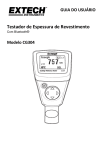
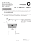
Nothing else measures up!
Prospect House
George Cayley Drive
Clifton Moor
York
England
YO30 4XE
Tel: +44 (0) 1904 692723
Fax: +44 (0) 1904 690385
E-Mail: [email protected]
...for secure online ordering of all our products!
Ref:.. \operat98\instructions 15\346010.qxp 05-01-15
Compact Coating
Thickness Meter
Code: 346010
Operating
Instructions
©York Survey Supply Centre 2015
Compact Coating
Thickness Meter
occasional measurements. It provides statistical analysis.
Single values are not saved. The statistical analysis
program can evaluate 80 readings.
• GROUP mode permits measurement and storage of
readings in a free programmable memory. A maximum of
400 readings and 4 series of measurements can be
analyzed according to various statistical criteria.
1. General Information
The DT-156 coating thickness gauges work either on the
magnetic induction principle or on the eddy current principle,
depending on the type of probe used. You can select the
type of probe via MENU system, or it will work automatically.
The gauges conform to the following industrial standards:
GB/T 4956-1985
GB/T 4957-1985
JB/T 8393-1996
JJG 889-95
JJG 818-93
1.3 Supply Schedule
• Gauge with two 1.5V batteries, plastic carrying case,
operating instructions, steel and aluminium substrate.
• USB connecting cable
• Program disc for Windows 98/2000/xp/Vista/7
1.4 Probe
The probe systems are spring-mounted in the probe sleeve.
This ensures safe and stable positioning of the probe and
constant contact pressure. A V-groove in the sleeve of the
probe facilitates reliable readings on small cylindrical parts.
The hemispherical tip of the probe is made of hard and
durable material. Hold the probe by the spring-mounted
sleeve and put on measuring object.
Features
• Measured Coatings: Non-magnetic coatings (e.g. paint,
zinc) on steel; insulating coatings (e.g. paint, anodizing
coatings) on non-ferrous metals
• Operating with MENU easily
• Two measuring modes: CONTINUE and SINGLE mode
• Two working modes: DIRECT and GROUP mode
(4 groups)
• Statistic Display: AVG, MAX, MIN, NO., S.DEV
• One point calibrating and two points calibrating
independently for each working mode
• Zero calibrating easily
• Memory for 320 readings (80 for each group)
• Delete single readings and all group readings easily
• High alarm and Low alarm for all working modes
• Low battery, error indication
• USB interface for PC analysis software
• Disable Auto-Power-Off function via MENU setting
1.5 Specifications
Ref:.. \operat98\instructions 15\346010.qxp 05-01-15
F
N
Measuring range
0~1250µm
0~49.21mils
0~1250µm
0~49.21mils
Working principle
Guaranteed
tolerance
(of reading)
1.1 Application
• This compact and handy gauge is designed for
non-destructive, fast and precise coating thickness
measurement. The principal applications lie in the field of
corrosion protection. It is ideal for manufacturers and their
customers, for offices and specialist advisors, for paint
shops and electroplaters, for the chemical, automobile,
shipbuilding and aircraft industries and for light and heavy
engineering.
• DT-156 gauges are suitable for laboratory, workshop and
outdoor use.
• The probe can work on both principles, magnetic induction
and the eddy current principle. One probe only is required
for coating measurement both on ferrous and non-ferrous
metal substrates. It is adaptable to specific tasks: i.e. they
can be used on special geometries or on materials with
special properties.
1.2 Description of the Gauge
• For measurement on steel substrates, the gauge works on
the magnetic induction principle, for measurement on
non-ferrous metal substrates, it works on the eddy current
principle.
• Measurement values and user information are shown the
LCD, a display backlight ensures easy reading of screen
data in dark conditions.
• Two different operating modes are available: DIRECT mode
and GROUP mode.
• DIRECT mode is recommended for simple, quick,
Sensor probe
Precision
Min. curvature radius
Diameter of min. area
Magnetic Induction
0~850µm
(±3%+1µm)
850µm~1250µm
(±5%)
0~33.46mils
(±3%+0.039mils)
33.46mils~49.21mils
(±5%)
0~850µm
(±3%+1µm)
850µm~1250µm
(±5%)
0~33.46mils
(±3%+0.039mils)
33.46mils~49.21mils
(±5%)
0~50µm (0.1µm)
50µm~850µm (1µm)
850µm~1250µm
(0.01µm)
0~50µm (0.1µm)
50µm~850µm (1µm)
850µm~1250µm
(0.01µm)
1.5mm
3mm
0~1.968mils
(0.001mils)
1.968mils~33.46
mils (0.01mils)
33.46mils~49.21mils
(0.1mils)
7mm
Basic critical thickness 0.5mm
0~1.968mils
(0.001mils)
1.968mils~33.46
mils (0.01mils)
33.46mils~49.21mils
(0.1mils)
5mm
0.3mm
Working temperature
0°C~40°C (32°F~104°F)
Size (HxDxW)
110 x 50 x 23mm
Working RH
2
Eddy Current
Weight
20%~90%
100g
7
©York Survey Supply Centre 2015
• Now take approx. 10 readings on the uncoated,
shot-blasted sample to produce the mean value Xo.
• After this take approx. 10 further readings on the coated,
shot-blasted test sample to produce the mean value Xm.
• The difference between the two mean values is the mean
coating thickness Xeff over the peaks. The greater standard
deviation S of the two values Xm and Xo should also be
taken into consideration: Xeff = (Xm - Xo) ± S
Method B:
• Carry out a zero calibration of 10 readings on a
shot-blasted, uncoated sample. Then carry out a foil
calibration on the uncoated substrate. The foil set should
consist of a number of individual foils of max. 50 microns
thickness each and should roughly correspond to the
estimated coating thickness.
Method C:
This method also gives reliable results. Simply follow the
two-point calibration method using 2 foils as described in
section 4.2.3. For a maximum approach to the respective
nature of the surface, the foil value can be reached by using
several foils - 50µm each. The mean coating thickness
should be calculated from 5... 10 readings. The statistics
program is very useful here.
NOTE: For coatings thicker than 300µm, the influence of
roughness generally is of no importance and it will not be
necessary to apply the above calibration methods.
system for details, the DIR statistics will be lost. The
following statistical values are calculated:
NO: Number of readings in Work Mode.
AVG: Average value.
Sdev: Standard Deviation.
MAX: Maximum reading.
MIN: Minimum reading.
6.1 Statistical Terms
Average value ( )
The sum of readings divided by the number of readings.
Standard Deviation (Sdev.)
The sample standard deviation is a statistic that measures
how “spread out” the sample is around the sample mean.
The sample standard deviation increases with increasing
spread. The standard deviation of a set of numbers is the
root mean square of the variance S2.
The variance of a list is the square of the standard deviation
of the list, that is, the average of the squares of the
deviations of the numbers in the list from their mean divided
by the (number of readings -1)
Variance
Standard deviation
NOTE: Deletion must take place immediately after an outlier
or erratic reading has been taken. See the Delete function in
the MENU system.
4.3 General Remarks on Measurement
• After careful calibration has been made, all subsequent
measurements will lie within the guaranteed measuring
tolerance.
• Strong magnetic fields near generators or live rails with
strong currents can affect the reading.
• When using the statistics program for obtaining a mean
value it is advisable to place the probe several times at a
typical measuring spot. Any false readings or outliers can
be removed immediately via the MENU system.
• The final reading derives from the statistical calculation and
from the guaranteed tolerance levels of the gauge.
Coating thickness D = X ± s ± µ.
6.2 Storage Capacity Overflow
• In GROUP mode, if the storage capacity is exceeded,
statistics will not be updated, although measurement can
continue. If the memory is full, subsequent readings will be
omitted from the statistics. They will be marked with “FULL”
in the LCD (in single measuring mode).
• In DIRECT mode, if the memory is full. The newest reading
will replace the oldest reading and the statistics will be
updated.
7. Delete Functions
In MENU system, you can find the following functions:
• Delete current data: If you find the last measuring reading is
wrong, you can delete it via this function. At the same time,
the statistics will be updated.
• Delete all data: You can delete all data and statistics of the
Current Work Mode.
• Delete group data: This function includes “delete all data”
function. In addition, this function will delete HIGH alarm,
LOW alarm and One and Two Point Calibrations.
Example:
Readings: 150µm, 156µm, 153µm
Mean value: X = 153µm
Standard deviation: s = ±3µm
Measuring uncertainty: µ = ±(1% of reading + 1µm)
D = 153 ± 3 ± (1.53µm + 1µm)
= 153 ± 5.5µm
5. Limit Function
• Limits can be entered in DIRECT and a selected GROUP
memory at any time, i.e. before, during and after a series of
measurements. There are practical uses for limits.
• Any reading which falls outside the set tolerance limits will
be registered by a warning indication:
H: reading above HI limit.
L: reading below LO limit.
Please set the limit values using MENU system.
6. Measurement Using Statistics
The gauge calculates statistics from a maximum of 80
readings (GRO1 ~ GRO4: in total, a maximum of 400
readings can be stored). In addition, readings can’t be stored
in DIR mode, but it can calculate statistics as GRO1 ~
GRO4. When power off or changing Work Mode (see MENU
Ref:.. \operat98\instructions 15\346010.qxp 05-01-15
2.3 Menu System and Basic Settings
2.3.1 Menu System
Press to power on; the gauge will work in measuring mode.
Press red bar button into MENU mode. See following MENU
system arrangements.
NOTE: MENU system arrangements need to be known well
for your works.
Menu
>Statistic view
>>Average view
>>Minimum view
>>Maximum view
>>Number view
>>Sdev view
>Options
>>Measure mode
>>>Single mode
>>>Continuous mode
>>Working mode
>>>Direct
>>>Group 1
>>>Group 2
>>>Group 3
>>>Group 4
>>Used probe
>>>AUTO
>>>Fe
>>>No Fe
>>Unit settings
>>>µm
>>>mils
>>>mm
>>Backlight
>>>ON
>>>OFF
>>LCD Statistic
>>>Average
>>>Maximum
>>>Minimum
>>>Sdev.
>>Auto power off
>>>Enable
>>>Disable
>Limit
>>Limit settings
>>>High limit
>>>Low limit
>>Delete limit
>Delete
>>Current data
>>All data
>>Group data
>Measurement view
>Calibration
>>Enable
>>Disable
>>Delete Zero N
>>Delete Zero F
1.6 Front View
8. Gauge Control via PC
All measuring readings of all work modes can be
downloaded to PC via USB port for data analysis.
See software guide for more details.
6
9. Troubleshooting
The following list of error messages explains how to identify
and eliminate faults:
Err 1, Err2, Err3: Connecting of probe fault; deviant signal
Err1: Eddy current probe
Err2: Magnetic induction probe
Err3: Both probes
Err4, Err5, Err6: Reserved
Err7: Thickness fault.
1. Probe
2. Power ON/OFF key
3. Zero Calibration key
4. Down/Right key
5. Blue key for ESC/NO/BACK function in menu mode, or
backlight ON/OFF in working mode
6. Main display for coating thickness
7. Measuring unit
8. NFe: indicates readings on non-ferrous metals;
Fe indicates readings on ferrous metals
9. Indicates the probe working principle: AUTO, Magnetic
Induction or Eddy Current
10. Indicates that the gauge is currently controlled via PC
11. USB connecting port
12. Low battery
13. Working mode indication: DIRECT or GROUP
14. Statistic display: AVG, MAX, MIN, SDEV
15. The statistic number of measuring readings
16. Red key for OK/YES/MENU/SELECT in menu mode
17. Up/Left key
2. Preparing
2.1 Power Supply
For checking the battery’s state of charge, please press
key:
No LC Display: Battery missing or battery charge too low to
illuminate display.
Display: gauge switches off after about one second:
Replace battery immediately.
Note that the gauge will make faulty measurements if the
voltage is very low.
2.2 Replacing the Battery
• Place the gauge upside-down on a suitable surface
• Remove the screws from the battery compartment with a
cross tip screwdriver
• Raise the lid of the compartment
• Remove the battery
• Insert new battery
• Close the lid and fasten with screw
Caution: Make sure the anode and cathode are correctly
positioned
3
2.3.2 Basic Settings
Please refer to the MENU arrangement. According to the
LCD indication, press the red bar button for
OK/YES/MENU/SELECT operating functions. Press the blue
bar button for ESC/NO/BACK operating functions. Press the
UP/DOWN button to switch the selected item.
©York Survey Supply Centre 2015
2.3.2.1 Measure mode
• Continuous measurement mode: It can sometimes be of
advantage if the probe does not need to be raised between
each measurement so that there is a running display of
readings. In continuous mode, readings are not
accompanied by a bleep. All readings taken in this mode
will automatically be entered into the statistics program as
long as sufficient memory is available.
• Single mode: In Single mode, readings are accompanied by
a bleep. Otherwise same as Continuous measurement
mode.
mode, all readings will be cleared but the statistic values
won’t be changed until logging new measurement readings.
The readings and statistical values can be shown on the
LCD screen. The statistical analysis program can evaluate
80 readings. When the memory is full, new readings will
replace old readings. In this mode, it has individual
calibration values and limit values.
• In GROUP mode, every group memory can store a
maximum of 80 single readings and 5 statistic values.
Calibration values and limit values can individually be set
and stored for every group. When the memory is full,
measuring will continue but not be stored and statistic
values won’t be changed. If needed, you can delete group
data and statistic values, and reset calibration values and
limit values.
• You can select DIRECT and GROUP mode in MENU
system.
NOTE: in order to work in GROUP mode, e.g. to calibrate,
take readings, set limit, the word “GROX” must appear on the
LCD screen, if not, you can set measurement in the MENU
system.
• Press while holding the probe in the air. The gauge will
work in DIRECT mode. And the last reading will be shown
(if available).
2.3.2.2 Used probe
The probe can work in three modes.
AUTO: The probe can automatically select the working
mode. When placed on steel (magnetic substrates), it will
work in magnetic induction principle. When placed on
non-ferrous metals, it will work in eddy current principle.
Fe: The probe works in magnetic induction principle.
No-Fe: The probe works in eddy current principle.
2.3.2.3 Unit Settings
You can switch from Metric units (µm, mm) to Imperial (mils).
in “µm” mode, the unit will switch to “mm” automatically when
value of reading exceeds 850µm, see the specification
section for more details.
4. Calibration and Measurement
4.1 General Hints for Calibration
4.1.1 Calibration methods
There are four different methods available for calibration:
• Basic calibration: recommended for measurement on even
surfaces and if the measuring object has the same material,
size and curvature as the zero plate attached to the casing.
• Zero point calibration: recommended if measuring errors up
to ±(3% of reading plus constant error of probe) are
permitted. (Example of constant probe error: Fe 1µm;
no-Fe 1.5µm)
• One point calibration (calibrating using a calibration foil):
recommended if readings to be expected will be close to the
calibration value and if the permitted error of probe will be
max. ±(1%...3% of reading plus constant probe error).
• Two point calibration (using a set of two calibration foils).
A) Recommended for measurements on rough surfaces.
B) Recommended for precise measurements on smooth
surface if the thickness to be expected lies between that of
the two calibration foils.
2.3.2.4 Total Reset
A total reset erases data from all memories. This includes all
sets of readings of all work modes plus their associated
statistics, calibration values and tolerance limits.
• Switch off gauge.
• Press ZERO and simultaneously.
• The LCD displays “sure to reset”, press the red bar button
for YES or blue bar button for NO.
• The gauge will restart automatically.
2.3.2.5 Backlight
You can select ON/OFF in MENU system. Besides, in
measuring mode, press the blue bar button once to switch
ON/OFF the backlight.
2.3.2.6 LCD Statistic
In Menu system mode, the statistic display can be selected
between Average, Maximum, Minimum and Sdev. When
returned to measurement mode, it will be displayed on the
lower right of the LCD. At the same time, the statistic number
of measuring readings is displayed on the lower left of LCD.
Via “statistic view” item in MENU system, you can look
through all statistic values for the current group.
4.1.2 Storing Calibration Values
If the gauge is calibrated for a particular purpose, the
calibration values will be stored in memory until changed.
NOTE: The calibration procedure should be restarted from
the beginning if:
• An incorrect reading has been taken.
• An incorrect command has been entered.
• The gauge has switched off.
2.3.2.7 Measurement view
Via “Measurement view” in MENU, you can look through all
measurement readings for current group.
2.3.2.8 Auto power off
You can disable Auto-power-off via the MENU system or the
gauge will power off automatically after about 3 minutes.
3. Measuring, Storage and Data Processing in
Direct and Group Mode
This gauge offers two operating modes: DIRECT and Group
mode. The GROUP mode includes GRO 1~4.
• DIRECT mode is intended for quick occasional readings. In
this mode, individual readings are logged to memory
provisionally. When powered off or switched to GROUP
Ref:.. \operat98\instructions 15\346010.qxp 05-01-15
4
4.1.3 Calibration Example
Calibration is the most important requirement for accurate
measurement. The more closely the calibration sample
matches the product sample, the more accurate the
calibration, and therefore the reading, will be. If, for instance,
a product is to be measured on a steel cylinder, quality ST37
(mild steel), diameter 6mm, the calibration of the uncoated
sample must take place on a steel cylinder of similar quality
with the same diameter.
The calibration sample must correspond to the product
sample in the following ways:
required foil thickness. The thickness of the foil should be
roughly equivalent to the estimated coating thickness.
• Repeat step 2 several times. It will get the mean value of
previous calibration readings.
• Now take readings by placing the probe on the coating and
raise it if steady.
• It may be necessary to delete calibration, e.g. after entry of
a faulty calibration value: MENU>delete>delete group data
(NOTE: It will delete all data, limit data, one-point and
two-point calibrations except for zero-point calibration).
• This will reactivate the default basic calibration for use on
even surfaces.
NOTE: The meter calculates the mean of the last 5
calibration readings. When full, the newest calibration
value will replace the oldest calibration value.
• Press blue bar button to exit current calibration. Or else,
after about 30 seconds, the calibration will become effective
automatically.
• Press ZERO button to make current calibration effective
compulsively. Even while a series of measurements is being
taken, foil calibration can be carried out often as necessary.
The old calibration will be overwritten; the Zero calibration
remains in memory.
• Curvature radius
• Substrate material properties
• Substrate thickness
• Size of measuring area
• The point at which the calibration is made on the calibration
sample must always be identical with the point of
measurement on the product itself, especially in the case of
corners and edges of small parts.
4.1.4 High Accuracy Calibration
To achieve high-accuracy readings, it is advisable to log
calibration values (both zero values and calibration foil
values) several times in succession. In this way, the gauge
will automatically establish a mean calibration value. For
more details see 4.2 Special Hints for Calibration. The high
accuracy calibration is an obvious advantage when
calibrating on uneven, e.g. shot-blasted, surfaces.
4.1.5 Cleaning the Measuring Point
Before calibration the measuring point of the probe tip must
be free from grease, oil, scraps of metal, etc. The slightest
impurity will affect measurement and distort readings.
4.2 Special Hints for Calibration
The basic calibration stored in the gauge should only be
used for measurements on even surfaces, i.e. on steel
components made of conventional steel (mild steel) or on
aluminium components.
Firstly, you can turn into Calibration Mode via MENU system
(Menu>Calibration>Enable). Then the LCD will show “Cal
n(or 1~2) Zero n(or y)”. The “n” means not any point
calibration and Zero calibration and “y” means “there is Zero
calibration”. “Cal 1~2” means “there is One or Two point
calibration”. After finishing all calibration tasks, we advise that
you disable calibration via the MENU system.
Preparing to calibrate:
• Switch the gauge on (at least 10cm from any metal).
• Substrate sample and necessary foils (calibration standard)
• Set work mode: continuous or single, via MENU.
4.2.3 Two-Point Calibration
• Suggest that gauge is in single work mode. If necessary
switch to the mode via the MENU system. This method
requires the use of two different foils. The thicker one
should be, if possible, 1.5 times as thick as the thin one.
• For best results, the thickness to be expected should be
somewhere between the two calibration values.
• This method is especially suitable for taking measurements
on rough shot-blasted surfaces or for high-precision
readings. It is advisable to take a mean for several times.
This considerably reduces the effect of scattering which
occurs during calibration of upper and lower values.
The calibration foils may be used in any order.
• Zero point calibration according to section 4.2.1
• The first point calibration according to section 4.2.2
• Repeat step 2
• Take readings by placing the probe on the coating to be
measured and raise it after the beep. The reading is shown
on the display.
NOTE:
• Apply the probe to test sample several times.
• The thickness of the foil should be roughly equivalent to the
estimated coating thickness.
• Even whilst a series of measurements is being taken, foil
calibration can be carried out as often as necessary. The
old calibration will be overwritten; the ZERO calibration
remains in memory until you next make a Zero point
calibration.
• See one-point calibration for more information.
4.2.1 Zero Point Calibration (No need to enable calibration)
• Place the probe on uncoated sample (zero coating
thickness) vertically and rapidly.
• The LCD shows <x.xµm>. Operating is different in
continuous mode and single mode. See the work mode
section for more details. Then, raise the probe rapidly (at
least 10 cm from metal substrate).
• Press and hold the ZERO button for about 1.5 seconds, the
LCD will show 0.0µm. The calibration is finished.
• Repeat this procedure several times. The calibration
system always saves the mean value of the previous
calibration points.
NOTE: You can delete the old zero point calibration before
making a new zero point calibration via the MENU system.
The meter always calculates the mean of the last 5
calibration readings. When full, the newest calibration value
will replace the oldest calibration value. We suggest that you
make a Zero calibration when starting a measurement.
4.2.2 One-Point Calibration
This method is recommended for high precision
measurements, measurements on small parts and on
hardened and low-alloy steel.
• Zero point calibration according to section 4.2.1
• Lay the calibration foil on an uncoated sample, apply the
probe and raise it if steady. Press UP or DOWN to adjust
5
4.2.4 Shot-Blasted Surfaces
The physical nature of shot-blasted surfaces results in
coating thickness readings that are too high. The mean
thickness over the peaks can be determined as follows
(not that the statistics program is of great benefit in this
procedure):
Method A:
• The gauge should be calibrated according to 4.2.2 or 4.2.3.
Use a smooth calibration sample with the same curvature
radius and the same substrate as the later measuring
sample.
©York Survey Supply Centre 2015