1
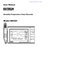
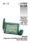
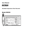
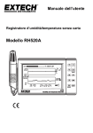
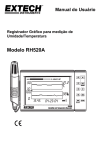
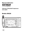
Nothing else measures up!
Prospect House
George Cayley Drive
Clifton Moor
York
England
YO30 4XE
Tel: +44 (0) 1904 692723
Fax: +44 (0) 1904 690385
E-Mail: [email protected]
...for secure online ordering of all our products!
Ref:.. \operat98\instructions 15\330720.qxp 05-01-15
Humidity/
Temperature
Chart Recorder
Code: 330720
Operating
Instructions
©York Survey Supply Centre 2015
Humidity/Temperature Chart Recorder
Operating Instructions
Introduction
Congratulations on your purchase of the ExTech RH520 Temperature & Humidity Chart Recorder. The RH520 measures and displays Temperature, Humidity and Dew Point.
SAMPLE RATE DISPLAY
1. Press the VIEW and the TIME buttons simultaneously from the standard view mode
2. Both numerical displays will switch off so that the LCD can show only the sample rate in minutes (the MIN display icon will switch on)
3. The projected TIME-DAYS that the internal memory will be full (based on current sample rate) is displayed in the TIME and DATE display
areas
4. To change the sample rate, refer to the programming section of this manual
5. Press the VIEW button to return to the standard view
Sample rate in minutes
The remote (detachable) probe senses the ambient conditions while the LCD display graphs and provides numerical representation of the
readings. Programmable audio-visual alarms alert the user when ambient conditions reach alarm presets. The optional alarm module permits automatic relay switching when alarm presets are reached.
MINUTES indicator
Displays how long it will take to finish
recording in hours:minutes
months/days/years.
Not the actual date.
The RH520 Internal Memory can store up to 49,152 measurements for later transfer to a PC. Careful use of this instrument will provide years of reliable service.
Specifications
Display:
Temperature measurement range:
Humidity measurement range:
Dew point temperature:
Accuracy:
Internal memory storage:
Sampling interval:
Graph scaling:
Low battery indication:
Power supply:
Battery life:
Operating temperature:
Operating humidity:
Dimensions:
Weight:
RH520 DESCRIPTION
Large backlit graphical LCD
-28 to 60°C (-20.0 to 140.0°F)
10 to 95%
-28 to 60°C (-20.0 to 140.0°F)
±3.0%RH and 1°C (1.8°F) for temperature
49,152 complete reading sets
Selectable recording rate: 0.1 to 199.9 minutes
User selectable in 10°F, 5°C and 10% increments
5-segment battery indicator
3x AA batteries and AC adaptor (included)
4 weeks typical, using alkaline batteries
CONTROL MODULE and DISPLAY: 0 to 50°C (0 to 120°F)
SENSOR: -28 to 60°C (-20.0 to 140.0°F)
CONTROL MODULE and DISPLAY: 90%RH max.
SENSOR: 95%RH max.
127 x 196 x 23mm (5.0 x 7.7 x 0.9”)
357g (12.6oz)
Transfer logged readings using the PC interface
The DATA jack on the right side of the meter is used to connect the RH520 to a PC. The supplied communication cable connects to the DATA jack
on the meter and a serial (9-pin) jack on the PC.
When the communication cable is connected to the meter, the meter begins sending the contents of it’s internal memory out through the cable. For
this reason, connecting the meter is the last step as described in the communication procedure below:
1. Store readings in the RH520 as described elsewhere in this manual. Up to 49,152 readings can be stored. However, for the first test, try only a
few readings in order to confirm the operation of the data transfer process.
2. Open a Windows-based data capture program (see Appendix in rear of manual for recommended programs).
3. Set the data capture program options to BAUD RATE: 57,600; DATA BITS:8; PARITY: NONE; STOP BITS: 1; and use XON/XOFF MODE.
4. Connect the 9-pin serial connector side of the supplied communications cable to the PC serial port.
5. Connect the other end of the communications cable tot eh RH520 data jack.
6. The stored readings will automatically appear in the data capture program screen.
Alarm Conditions and the Alarm History
When in standard view mode:
• If the ALARM display icon is flashing - an alarm condition currently exists.
• If the ALARM display icon is ON steady - there are past alarms to view in the alarm history. Use the ALARM button to view the alarm history as
described elsewhere in this manual.
• If an alarm is tripped, press the ALARM button to silence it.
• Press and hold the SET button for 2 seconds to clear an alarm through the external relay module.
When in Alarm View or Time View mode:
• If the ALARM display icon is flashing - the cursor is currently on an alarm condition.
• If the ALARM display icon is ON steady - there are past alarms to view in the alarm history. Use the cursors or the ALARM button to view the
alarm history as described elsewhere in this manual.
Note that the alarm display icon and the external alarm relay module can be controlled separately as indicated in the statements above.
Factory Default Settings
• Default LCD mode: standard view
• Temperature graph vertical resolution: 0 to 100°F
• RH graph vertical resolution: 0 to 100%
• TEMP and RH alarm limits: 0 (low) and 100 (high)
• Sample rate: One (1) reading stored per minute
1. Remote sensor
2. Sensor cable
3. LCD display
4. Swivel keypad/tabletop stand
5. PC interface jack
6. Universal alarm module jack
7. AC adaptor jack
8. DATA RESET button (clears recorded measurement data and
alarm history)
9. Temperature units select switch (C or F)
10. PROGRAMMING RESET button (clears programming
changes but retains measurement data and alarm history)
11. Display CONTRAST adjust
12. Sensor cable storage area
13. 1.5V AA batteries
14. Sensor cable run
15. Wall mount holes
Ref:.. \operat98\instructions 15\330720.qxp 05-01-15
Battery Replacement
The 5-segment battery life indicator allows the user to track the status of the battery. When all 5 segments are dark, the battery is fully charged.
Segments switch off as the battery ages. When the battery indicator has only one segment left the batteries must be replaced immediately.
1. Open the battery compartment on the rear of the instrument
2. Remove the old batteries and replace with three (3) heavy duty alkaline ‘AA’ batteries, observing polarity
3. Replace the battery compartment cover securely
4. The RH520 will require a “programming reset” to reset the display. Press the RESET button located inside the battery compartment. “Reset”
clears all settings. Time, Date and the logging interval need to be entered. The measurement data and alarm history, however, will still be
retained in the non-volatile memory.
Optional Alarm Relay Module
The alarm output jack, located on the swivel push-button stand, drives the optional remote alarm relay module (cable and relay. The relay module
can be used to power external warning or switching devices when programmed alarm limits are reached. Refer to the manual supplied with the optional module for connection information.
Software
Software operational instructions are located on the software disc.
1
6
©York Survey Supply Centre 2015
MAX/MIN DISPLAYS
MAX or MIN indicator
is ON when in the
MAX or MIN mode
1. Press the VIEW button in the standard view to display the highest (MAX) and lowest (MIN) temperature and RH readings from all of the stored
measurement records.
2. When viewing the highest readings, the MAX indicator will switch on. When viewing the lowest readings, the MIN icon will switch on.
3. The cursor will move to the location of the MIN or MAX reading within the graph. If not within the graph currently displayed, the cursor will
move to the right most position and the graph will shift accordingly so that the relevant data point can be viewed.
4. Use the VIEW button to step through the highest and lowest temperature readings and then the highest and lowest RH readings. When the
MAX or MIN indicator is ON under the temperature reading digits, the display is showing the MAX or MIN temperature. When the MAX or MIN
indicator is ON under the RH reading digits, the display is showing the MAX or MIN relative humidity.
ALARM DISPLAYS
1. Press the ALARM button from the standard view to analyse the most recent alarm activity (temperature or humidity), if any. The ALARM
display icon and the relevant upper (temperature) or lower (RH) graph pixel will flash.
2. The cursor will move to the location within the graph. If not within the graph currently displayed, the cursor will move to the right most position
and the graph will shift accordingly so that the relevant data point can be viewed.
3. Press the ALARM button again to view the second most recent set of alarms (if no alarms, the standard view will appear).
4. Press the ALARM button again to view the third most recent set of alarms (if no alarms, the standard view will appear).
5. This procedure can continue until no further alarms exist and pressing the ALARM button will only bring up the standard view.
6. In the example diagram, the RH520 is showing a high temperature alarm (MAX and ALARM indicators on).
MAX temperature
alarm mode
DISPLAY DESCRIPTION
1. Temperature measurement graph
2. Internal memory usage meter
3. Vertical axis scale limits
4. Cursor/Alarm indicators
5. Push button lock out status indicator
6. Time display
7. Relative humidity (RH) measurement graph
8. Date display
9. Function indicators
10. Numerical temperature reading display
11. Numerical RH reading display
12. Battery status indicator
PUSH BUTTON DESCRIPTION
VIEW
USING THE CLOCK TO SORT THROUGH STORED READINGS
1. Press the TIME button in the standard view mode
2. Use the ARROW buttons to select a particular time of day
3. The temperature and humidity readings for the selected time will display
4. Press VIEW to return to the standard view
ALARM
TIME
Ref:.. \operat98\instructions 15\330720.qxp 05-01-15
5
RH
¢
¡
¤
Display a reading stored at a specific time and date
Set and display the recording sampling rate
Set the time and date
Used in combination with other buttons to set the vertical graph range
Used in combination with other buttons to set temperature alarm values
Used in combination with the RH button to display dew point
TEMP
DEW POINT DISPLAY
Press the TEMP and the RH buttons simultaneously to view the Dew Point reading. The DEW POINT display icon will switch on above the temperature. See the diagram below. Press VIEW to return to the standard view mode.
Display or set alarm values
Used in combination with other buttons to set parameter values
Stores new parameter values and returns to the standard view
SET
Use the arrow buttons to scroll to the desired time. Readings recorded at the selected time will display
Return the LCD to the standard view
Escape from any setting function without storing value changes
Scrolls highest and lowest (MAX/MIN) readings when in standard view
£
Used in combination with other buttons to set the vertical graph range
Used in combination with other buttons to set RH alarm values
Used in combination with the TEMP button to display dew point
Right, left, down and up arrow buttons for scrolling data and navigating the display
KEYPAD QUICK REFERENCE (ALSO SHOWN ON REAR OF THE RH520 HOUSING)
Key-press
VIEW
SET
ARROW KEYS
TIME
TEMP + RH
ALARM
SET + TEMP + ALARM
SET + RH + ALARM
TIME + VIEW
Function
Selects view mode
Saves new settings
Scroll through selections
View reading at specific time/date
View dew point temp
Step back through ALARM points
Enters set TEMP alarm mode
Enters set RH alarm mode
View sample rate
Second/Alternate Keystrokes
VIEW modes: Normal, TEMPmax, RHmax, TEMPmin, RHmin
VIEW to cancel, exit mode
Moves cursor through stored points
Arrow keys to select, VIEW to exit
VIEW to exit
ALARM selects next alarm, VIEW to exit
ALARM selects HIGH/LOW, SET to save
ALARM selects HIGH/LOW, SET to save
VIEW to exit
(continued...)
2
©York Survey Supply Centre 2015
Key-press
SET + TIME + VIEW
SET + TIME
SET + TEMP + UP
SET + RH + UP
Getting Started
Function
Enter set sample rate mode
Enter set time/date mode
Enter set TEMP vertical scale mode
Enter set RH vertical scale mode
Second/Alternate Keystrokes
SET to save, VIEW to exit
SET to save, VIEW to exit
TEMP selects upper/lower, SET to save
RH selects upper/lower, SET to save
POWER
1. The RH520 runs on battery power or AC adaptor (4.5VDC 300mA). Battery power consists of three (3) ‘AA’ batteries. See the Battery
Replacement section of this manual when changing/installing the batteries. Note: Batteries and adaptor are supplied.
2. Plug the AC adaptor in the AC adaptor jack shown in the Description section. The batteries will act as battery back up in the event of an AC
power failure.
3. Once the batteries are installed or the adaptor properly connected, the RH520 will begin displaying.
4. In the unlikely event that the AC power AND the battery back up fails, the RH520 will require a “Programming Reset” to reset the display. Press
the RESET button located inside the battery compartment. “Reset” clears all settings. Time, Date and the logging interval need to be entered.
The measurement data and alarm history, however, will still be retained in the non-volatile memory.
5. The 5-segment battery life indicator allows the user to track the status of the battery. When all five segments are dark, the battery is fully
charged. Segments switch off as the battery ages. When the battery indicator has only one segment left the batteries must be replaced
immediately.
NOTE: Always set the date and time immediately after batteries have been installed or after the RESET button has been pressed
MOUNTING THE RH520
The RH520 can be used in the following ways:
1. Placed on a table top where the swivel keypad is employed as a table stand
2. Wall mounted using the rear mounting holes
MEASUREMENT PROBE
The probe is attached to the meter with a 1 metre cable and can be used in two ways:
Stored in the RH520 probe cradle or simply held in hand.
PUSH-BUTTON LOCK-OUT SECURITY FEATURE
The RH520 can be secured from tampering by having it’s push-buttons locked.
1. Press for approx. 1 second and release the UP, DOWN, LEFT and SET arrow buttons simultaneously to lock out the push buttons.
Note: The security lock out can only be performed from the main view screen . If a scroll key or the time button was pressed prior to setting up
the lock out, the user must scroll back to the main screen.
2. Press for approx. 1 second and release the UP, DOWN, LEFT and SET arrow buttons simultaneously to restore the operation of the push
buttons.
Programming the RH520
SETTING THE TIME AND DATE
1. From the standard view, press the SET and TIME buttons simultaneously
2. the SET indicator will appear
3. Use the UP and DOWN arrow buttons to set the time
4. Use the LEFT and RIGHT arrow buttons to step through the minutes, hours, AM/PM/24-hour, day, month and year parameters
• If AM or PM is selected, the date format will be MONTH/DAY/YEAR
• if 24-hour is selected, the date format will be DAY/MONTH/YEAR
5. Press SET at any time to store the new value and revert to the standard view
6. Press VIEW at any time to return to the standard view without storing any changes
CLEARING THE INTERNAL MEMORY
Press the RESET button (located inside the battery compartment) to clear the display and measurement parameters (sample rate, vertical
resolution), and to reset the display.
Press the DATA RESET button (located on the back of the unit) to clear all of the stored readings, the MAX/MIN values and the alarm history.
SELECTING THE UNIT OF MEASURE FOR TEMPERATURE (°C/°F)
The °C/°F switch, located inside the battery compartment, is used to select the unit of measure for temperature displays.
SETTING THE VERTICAL RESOLUTION FOR THE TEMPERATURE GRAPHIC DISPLAY
1. Press the SET, TEMP and UP arrow buttons simultaneously
2. The upper temperature range indicator will flash and the SET icon will appear
3. Use the UP-DOWN buttons to change the upper temperature value (10° increments for °F, 5° increments for °C).
4. Press the TEMP button and the lower temperature range indicator will flash
5. Use the UP-DOWN buttons to change the lower temperature value (10° increments for °F, 5° increments for °C). Note that the upper and lower
temperatures cannot overlap and the upper value cannot be less than zero
6. Press the TEMP button to toggle upper and lower range values
7. Press the SET button at any time to store a value and return the instrument to the standard view
8. Press VIEW at any time to return to the standard view
SETTING THE VERTICAL RESOLUTION FOR THE RH GRAPHIC DISPLAY
1. Press the SET, RH and UP arrow buttons simultaneously
2. The upper RH range indicator will flash and the SET icon will appear
3. Use the UP-DOWN buttons to change the upper RH value in 10% increments
Ref:.. \operat98\instructions 15\330720.qxp 05-01-15
3
4. Press the RH button and the lower RH range indicator will flash
5. Use the UP-DOWN buttons to change the lower RH value in 10% increments
6. Note that the upper and lower RH values cannot overlap
7. Press the RH button to toggle upper and lower range values
8. Press the SET button at any time to store a value and return the instrument to the standard view
9. Press VIEW at any time to return to the standard view
SETTING THE RECORDING SAMPLE RATE
The sampling rate is the rate at which the RH520 automatically records measurements
1. Press the SET, VIEW and TIME arrow buttons simultaneously from the standard view
2. The current sample rate (in minutes) will appear in the numerical temperature display area
3. The whole minutes area of the numeric display will flash
4. The MIN and the SET icons will switch on. All other TEMP and RH indicators and numeric displays will switch off
5. The projected TIME and DAYS representing the moment the internal memory will be full (based on the sample rate) is displayed in the TIME
and DATE display areas
6. Use the UP-DOWN arrow buttons to increment/decrement the rate. Use the LEFT-RIGHT arrow buttons to step through the units of time
7. Sample rates can be set from 0.1 minutes up to 199.9 minutes
8. Press the SET button at any time to save changes and return to the standard view
9. Press VIEW at any time to return to the standard view without saving the changes
SETTING THE TEMPERATURE ALARM LIMITS
1. Press the SET, TEMP and ALARM buttons simultaneously from the standard view
2. The ALARM, SET and MAX indicators will switch on. All of the RH indicators will switch off
3. Use the UP-DOWN arrow buttons to increment/decrement the HIGH temperature alarm limit. Use the LEFT-RIGHT arrow buttons to step
through the decades
4. Press the ALARM button. The MIN (low alarm) indicator will switch on
5. Use the UP-DOWN arrow buttons to increment/decrement the LOW temperature alarm limit. Use the LEFT-RIGHT arrow buttons to step
through the decades
6. The HIGH and LOW alarm limits cannot overlap
7. Use the ALARM button to toggle between the HIGH and the LOW alarm limits
8. Press the SET button at any time to save changes and return tot he standard view
9. Press VIEW at any time to return to the standard view without saving the changes
SETTING THE RH ALARM LIMITS
1. Press the SET, RH and ALARM buttons simultaneously from the standard view
2. The ALARM, SET and MAX indicators will switch on. All of the TEMP indicators will switch off
3. Use the UP-DOWN arrow buttons to increment/decrement the HIGH RH alarm limit. Use the LEFT-RIGHT arrow buttons to step through the
decades
4. Press the ALARM button. The MIN (low alarm) indicator will switch on
5. Use the UP-DOWN arrow buttons to increment/decrement the LOW RH alarm limit. Use the LEFT-RIGHT arrow buttons to step through the
decades
6. The HIGH and LOW alarm limits cannot overlap
7. Use the ALARM button to toggle between the HIGH and the LOW alarm limits
8. Press the SET button at any time to save changes and return tot he standard view
9. Press VIEW at any time to return to the standard view without saving the changes
Display Modes
STANDARD VIEW
The standard view is the display state of the RH520 when it is turned on. Refer to the diagram in the display description section of this manual for
a representation of the standard view. To reach the standard view at any time, press the VIEW button. Note that the display automatically reverts to
the standard view five (5) minutes after the last button press.
CURSOR
The CURSOR location is indicated by a small diamond located between the two graphs. See diagram. There is one diamond for each horizontal
pixel in the graph (64 positions). The date, time and measurements for the data point selected by the cursor are shown in the Time/Date and numerical measurement display fields.
• Each press of the RIGHT ARROW button will move the cursor to the right. When the cursor reaches the right side limit , the graph will move to
the left. Holding the button down will speed the scrolling rate. When the cursor reaches the oldest (last) reading, it will stop.
• Each press of the LEFT ARROW button will move the cursor to the left. When the cursor reaches the left side limit , the graph will move to the
right. Holding the button down will speed the scrolling rate. When the cursor reaches the newest (latest) reading, it will stop.
• Each press of the UP ARROW button will shift the graph to the next set of 64 values; to the left of the one’s currently displayed (the cursor will
not move)
• Each press of the DOWN ARROW button will shift the graph to the next set of 64 values; to the right of the one’s currently displayed (the cursor
will not move)
4
©York Survey Supply Centre 2015