1
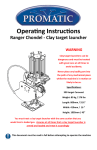
Operating Instructions
Wobble units - Merlin & Hobby
WARNING
Clay target launchers can be
dangerous and must be treated
with great care at all times to
avoid accidents.
Promatic International Ltd.
Promatic Inc.
Station Works,
Hooton,
South Wirral
CH66 7NF,
United Kingdom.
7803 West Hwy 116
Gower
MO 64454
USA.
Tel: +44 (0) 151 327 2220 (General)
+44 (0) 1407 860800 (Sales)
Fax: +44 (0) 151 3277075
Toll Free: 888.767.2529
Fax: 816.539.0257
E-mail [email protected]
E-mail: [email protected]
Website: www.promatic.co.uk
Website: www.promatic.biz
8 1.2 June 2014
Wobble Box Version
Never place any bodily part into
the path of any mechanical piece
whilst the machine is in motion or
likely to be so.
You must treat a clay target launcher with the same caution that you
would treat a loaded gun. Assume at all times thet a clay target launcher is
armed and loaded and treat it accordingly
This document must be read in full before attempting to operate the machine
12v DC Power Source:
This product is designed to be powered from a 12v DC battery, it
SHOULD NOT BE DIRECTLY CONNECTED TO HOUSEHOLD AC POWER
Battery: Where a trap is connected to any other suitable power source
i.e. a Transformer - the relevant sections of instructions should still be
observed, i.e. “Disconnect the battery” and applied to this or any other
power source.
How the Rotation box fits into the trolley
The rotation box forms the basis of the trolley spine. A swivel piece mounted to this
acts as a mount for the trap and replaces the trap’s existing base or foot.
If the trap is currently fitted to a trolley it should be removed and the trolley disassembled from its spine as some of the existing trolley components (axle handle etc..) will
be required to complete this assembly.
It the trap was mounted to a base then the kit purchased should also include the relevant trolley parts, please check that you have all the parts available.
Assemble the Rotation box to the existing trolley components:
Fit the trolley axle and wheels to the front (gear wheel) side of the rotation box.
Fit the extension tube to the rear end of the rotation box, followed by the trolley handle and ground spike using the clam-plates and fittings as shown below.
Fit second battery tray (Small battery version):
For traps using the budget trolley a second battery tray will need to be fitted. the second battery attaches to the opposite side of the pull handle as shown using the original
nuts & bolts. Fit the nylon spacer piece to the rear holes so that it sits between the two
trays using the extra nut & bolt provided.
Pull handle
Rotation box
Connecting the electrical wiring (continued):
The wiring for the elevation unit is fitted with piggyback type connectors, and should
be fitted to the existing motor connectors as shown below.
Replace any black plastic plugs in the ends of the elevation and/or rotation box
(taking care not to trap the electrical wiring ) and replace the motor cover using the
four screws previously removed.
New (elevation)
power cable
Fuse
Existing
(rotation)
power cable
Brown
Black
Blue
Rotation motor
Brown
Elevation box wiring:
If the wiring to the elevation box
has been removed for any reason,
it should be reconnected as shown
opposite.
The rotation disc on this box is
intended to turn clockwise to ensure smooth operation.
Blue
Extension tube
Second
Battery Tray
Nylon Spacer
Ground Spike assembly
2
How to operate:
Setting the switch to the ROTATION position will allow to motor to run continuously
varying the angle of the target. Pushing the switch forward to the NUDGE position will
give a momentary burst (the switch will automatically spring back to the OFF position)
this will allow a fixed trajectory to be selected.
Using the optional holes on the rotation disc a narrower or wider target field can be
selected
The elevation function can be switched on and off independently using the switch on
the back of the elevation box. Note: to set a fixed elevation it will be necessary to use
the NUDGE function with the elevation box turned on until the target is thrown at the
desired height, but please be aware that the trap will rotate as well during this procedure.
Once target is being thrown at the desired height the elevation function can be turned
off leaving just the rotation function active.
7
Fitting the elevation unit (continued):
Offer the box into position, fitting the keyhole slot on the rear box surface over the
two bolt heads fitted earlier . Next rotate the box upwards into position and locate
the front upper keyhole slot onto the casting plate nut loosened earlier. Finally slide
the box rearwards to fully locate it.
Assembling the optional kits:
Please read through the procedures for all the options you have purchased as some
steps may need to be combined when fitting two kits.
The kits may be delivered with certain parts already pre-assembled.
Assemble the Elevation bracket
(For traps with the elevation option)
Fit the stud through the mounting
hole in the swivel bracket and align
the locating peg with the square hole
fit the Large washer and nylock nut,
tighten securely.
The two main fixing bolts can now be fully tightened, followed by the front casting
plate nut. Refit the front and rear plastic caps, taking care not to trap the electrical
wiring in the process.
Connecting the electrical wiring:
The elevation box is connected into the existing rotation box, undo and discard the
white or light coloured blanking plug on the rotation box pass the wiring from the
elevation box through into the rotation box. Once the cable is fitted to the required
position, tighten the cable gland into the threaded hole (it may be necessary to slacken the rear part of the gland to allow it to spin on the cable during fitting)
Connect linkage to rotation wheel
(All versions)
Fit the linkage to the swivel piece (trap base) then fit a washer below and secure with
a spring clip. Fit the threaded spigot into any of the holes (other than the centre) of
the rotating wheel. Fit a washer to the spigot.
Fit the other end of the linkage to the threaded spigot and secure with a spring clip.
Trap mount
Elevation bracket (option)
Securing nut
Clip
Threaded Spigot
Washer
Washer
Threaded Spigot
Clip
Circlip
6
3
Install the electrical items and connect the battery:
Remove the motor cover on the underside of the rotation box .
The electrical assembly for the rotation box is supplied pre-fitted through the box
end-cap, feed the two wires (one with the fuse assembly) through the rear of the
box section.
Taking care not to damage the cable, fit the end cap into the rear of the rotation
box with the cable gland towards the left-hand side (when viewed from the rear)
Fix the small switch box to the battery tray using the small strip of adhesive Velcro.
Fitting the elevation unit:
If the elevation box is to be fitted the trap should now be mounted onto the trap carrier. Use a nylock nut and washer on the pivot point and the curved slot, tighten these
until the trap can just pivot freely on the base without binding.
Nylon spacer
Mounting bolt
Nylock nut
Elevation box
Casting plate nut
Connect the terminals to the
rotation motor.
The connector with the black wire
and the fuse holder fitted, should
be connected to the larger of the
two terminals, the connector with
the blue wire to the smaller terminal.
Replace the motor cover and secure with the four screws previously removed, however If you
have the elevation unit (optional)
to fit - leave this cover off until
later.
Install the second battery with the terminals facing in towards the handle. For Traps
fitted with the large battery tray this step is not necessary as the ring terminals provided on the cable be connected to the appropriate existing battery connector
Connect the battery: Ensure that the switch is in the OFF (centre) position and connect the cables to the battery.
The Black wire connects to the + (or red coloured) battery terminal
The Blue wire connects to the - (or black coloured) battery terminal
4
Elevation linkage & fittings
Fit the mounting bolts and spacers
to the mainframe mounting holes as
shown above, place a nylock nut on
each and hand tighten only, at this
stage the bolt heads need to remain
protruding.
Undo but do not fully remove the
forward casting plate nut, located
under the rectangular frame support
(nearest the main frame) allow
around 10mm clearance under the
nut to aid box location.
Remove the large black plastic plugs
from the ends of the elevation box
(taking care not to dislodge the electrical wiring from the motor) this will
allow a clear view of the internal
keyhole slots in the rear face of the
box.
Trap fixing Nut & Washer
Keyhole
slot
5