Transcript
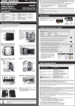
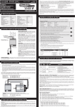
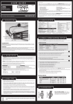
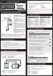
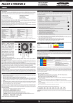
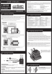
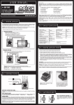
RC Dynamics Voltage Booster Installation and Operating Instructions Jordan Technologies Installation Find a convenient point to mount the Booster. Ideally allowing the input cables to be as short as possible, also allowing easy access to the inbuilt switch. Connect the input wires to the +ve and –ve of the 3.7V LiPo or 4 Cell NiMH pack. We recommend soldering the wires to the ESC posts or terminals if possible. Note that the wire identified with red heatshrink must be connected to the positive battery terminal. Plug the output connector into a spare socket in the receiver, ensuring that the polarity is correct. Again the wire identified with red heatshrink should be in the same position as other red(+ve) wires and that the other black wire is in the same position as the other black wires. Operation (Can vary slightly depending on the ESC type used, if in doubt please contact us for advise) Recommended for most ESCs including LRP/Nosram, GM Genius 2010- 90 and120 models, older generation GM Genius 120 Ensure that the ESC switch is left in the off position, hide this switch in the vehicle so that it cannot accidently be used. Where applicable set the ESC supply cut off voltage to the recommended voltage. Connect the Battery and switch the vehicle on and off using the booster switch. Tekin If not using a LiPo voltage cut off, use the recommended operating instructions above If using the Tekin ESC voltage cut off Ensure that the ESC switch is easily accessible Set the ESC supply cut off voltage to the recommended voltage. Connect the Battery and switch the vehicle on using both the ESC switch and off using the booster switch If you have any doubt please contact us. The booster works great with all ESCs types. [email protected] +447932794617