1
Operating Instructions
2K120/2K121
Initial Installation
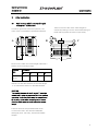
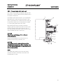
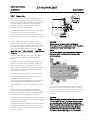
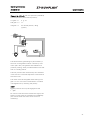
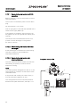
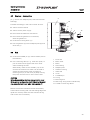
Diagram for shift unit with two positions (standard)
or three positions (with neutral position):
1st gear ==>
e. g. 4:1
2nd gear ==>
1:1
3rd gear ==>
S3 neutral position, idling
(option)
S3
1
optional
4
2
blue
grey
black
6
5
7
1
8
2
3
S1
green
M
4
4
3
X8
blue
black
grey
3
4
black
S2
blue
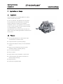
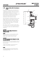
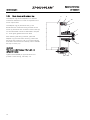
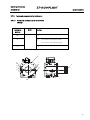
The electromotive gearchange is performed by a
shift unit on the gearbox which is driven by a DC
motor (24 V DC). The gearbox shift element is a
positively locking, axially movable selector fork that
acts on a sliding sleeve.
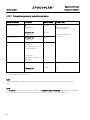
The limit positions are monitored by limit switches
in the shift unit. The time sequence is monitored in
the control unit.
The motor must be energized when shifting from
gear 1 to 2 or vice versa. The direction of rotation
is changed over by reversing the polarity.
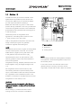
NOTE
Neutral position can only be engaged via the
1st gear.
As soon as limit switch S3 receives the signal, the
electric current must be switched off immediately
(this can be done with short-circuit control if
necessary).
21