1
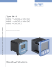
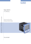
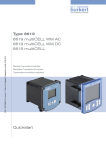
Type 8619
multiCELL
Modular transmitter/controller
Modularer Transmitter/Controller
Transmetteur/contrôleur modulaire
Operating Instructions
Bedienungsanleitung
Manuel d‘utilisation
We reserve the right to make technical changes without notice.
Technische Änderungen vorbehalten.
Sous réserve de modifications techniques.
© 2010 Bürkert SAS
Operating Instructions 1007/00_EU-ML_00561096_Original_FR
Type 8619
Contents
1.
About this manual.............................................................................................................................................................................................. 5
1.1.
2.
Symbols used................................................................................................................................................................................................. 5
Intended use............................................................................................................................................................................................................. 6
2.1.
Restraints.......................................................................................................................................................................................................... 6
2.2.
Foreseeable misuse.................................................................................................................................................................................... 6
3.
Basic safety information............................................................................................................................................................................ 7
4.
General information........................................................................................................................................................................................ 8
5.
4.1.
Contents of the delivery............................................................................................................................................................................ 8
4.2.
Warranty conditions..................................................................................................................................................................................... 8
4.3.
Information on the Internet..................................................................................................................................................................... 8
Description................................................................................................................................................................................................................ 9
5.1.
Area of application....................................................................................................................................................................................... 9
5.2.
General description..................................................................................................................................................................................... 9
5.2.1. Construction................................................................................................................................................ 9
6.
5.3.
Functional description..............................................................................................................................................................................10
5.4.
Functional diagram....................................................................................................................................................................................11
5.5.
Description of the product label.........................................................................................................................................................11
5.6.
Versions available.......................................................................................................................................................................................12
Technical data......................................................................................................................................................................................................13
6.1.
Conditions of use........................................................................................................................................................................................13
6.2.
Compliance to standards and directives.......................................................................................................................................13
6.3.
General technical data.............................................................................................................................................................................13
6.3.1. Mechanical data........................................................................................................................................13
6.3.2. Specifications of the "M0:MAIN" board..............................................................................................14
6.3.3. Specifications of the "pH/redox" module............................................................................................15
6.3.4. Specifications of the "COND" conductivity module........................................................................16
6.3.5. Specifications of the additional "OUT" outputs board....................................................................17
6.3.6. Specifications of the connection cables.............................................................................................17
1
english
Type 8619
7.
Installation and wiring...............................................................................................................................................................................18
7.1.
Safety instructions.....................................................................................................................................................................................18
7.2.
Building the device into a housing or cabinet............................................................................................................................18
7.3.
Electrical wiring............................................................................................................................................................................................20
7.3.1. Electrical connections.............................................................................................................................20
7.3.2. Wiring the M0:MAIN board....................................................................................................................20
7.3.3. Wiring the "OUT" outputs module.......................................................................................................23
7.3.4. Wiring the "pH/ORP" module...............................................................................................................23
7.3.5. Wiring the "COND" conductivity module...........................................................................................26
8.
Commissioning......................................................................................................................................................................................................27
8.1.
9.
Safety instructions.....................................................................................................................................................................................27
Adjustment and functions......................................................................................................................................................................28
9.1.
Safety instructions.....................................................................................................................................................................................28
9.2.
Functions.........................................................................................................................................................................................................28
9.3.
Using the navigation button and the dynamic keys.................................................................................................................29
9.4.
Modifying a name.......................................................................................................................................................................................30
9.5.
Entering a numerical value....................................................................................................................................................................33
9.6.
Description of the display......................................................................................................................................................................34
9.6.1.
Description of the icons.................................................................................................................................................................................................34
9.6.2. Switching on the device for the first time...........................................................................................35
9.7.
Read mode.....................................................................................................................................................................................................36
9.8.
Configuring mode access......................................................................................................................................................................37
9.9.
Parameters menu.......................................................................................................................................................................................38
9.9.1. Setting the multiCELL date and time...................................................................................................38
9.9.2. Selecting the display language.............................................................................................................38
9.9.3. Modifying the PARAMETERS menu access code...........................................................................38
9.9.4. Consulting and/or activating the available software options.........................................................38
9.9.5. Saving the data on the memory card...................................................................................................39
9.9.6. Loading data from the memory card....................................................................................................39
9.9.7. Restoring the default parameters of the Read mode and the outputs........................................40
9.9.8. Customising the "User views 1 to 4"...................................................................................................40
9.9.9. Renaming a process variable................................................................................................................42
2
9.9.10. Setting the display contrast and brightness......................................................................................42
english
Type 8619
9.9.11. Configuring an arithmetic function.......................................................................................................43
9.9.12. Configuring a "PROP" proportional function.....................................................................................44
9.9.13. Configuring an "ONOFF" control function.........................................................................................47
9.9.14. Configuring a PID (proportional integral drift) control function.....................................................50
9.9.15. Configuring a time dosing cycle...........................................................................................................57
9.9.16. Configuring a "Volume Dosing" function............................................................................................61
9.9.17. Configuring the "System switch" event...............................................................................................64
9.9.18. Datalogging (datalogger).......................................................................................................................66
9.9.19. Setting the parameters of the current outputs..................................................................................67
9.9.20. Setting the parameters of the digital outputs....................................................................................68
9.9.21. Setting the parameters of a pH/redox module..................................................................................73
9.9.22. Setting the parameters of a conductivity module.............................................................................75
9.10. Calibration menu.........................................................................................................................................................................................77
9.10.1. Activate/deactivate the Hold function.................................................................................................77
9.10.2. Modifying the Calibration menu access code...................................................................................78
9.10.3. Adjusting the current outputs................................................................................................................78
9.10.4. Resetting the totalizers...........................................................................................................................78
9.10.5. Entering the K factor for the used fitting or determining it using teach-in..................................79
9.10.6. Calibrating a pH or redox sensor..........................................................................................................82
9.10.7. Calibrating a conductivity sensor.........................................................................................................85
9.11. "Diagnostics" menu....................................................................................................................................................................................87
9.11.1. Modifying the "Diagnostics" menu access code..............................................................................87
9.11.2. Monitoring the pH or redox values.......................................................................................................87
9.11.3. Monitoring the conductivity of the fluid...............................................................................................88
9.11.4. Monitoring the temperature of the fluid...............................................................................................89
9.11.5. Reading the parameters of the pH, redox or conductivity sensor.................................................90
9.12. Tests menu.....................................................................................................................................................................................................91
9.12.1. Modifying the "Tests" menu access code...........................................................................................91
9.12.2. Checking that the outputs are behaving correctly............................................................................91
9.12.3. Checking that the outputs are working correctly..............................................................................91
9.13. Information menu.......................................................................................................................................................................................92
9.14. Structure of the configuring menus.................................................................................................................................................94
9.15. Process inputs or values.....................................................................................................................................................................107
9.15.1. On the M0:MAIN board....................................................................................................................... 107
9.15.2. On the pH/redox module..................................................................................................................... 108
english
3
Type 8619
9.15.3. On the conductivity module................................................................................................................ 108
9.15.4. On the additional outputs module..................................................................................................... 108
10.
Maintenance and troubleshooting.............................................................................................................................................109
10.1. Safety instructions..................................................................................................................................................................................109
10.2. Maintenance of the multiCELL..........................................................................................................................................................109
10.3. If you encounter problems.................................................................................................................................................................109
10.3.1. "Error" events related to the monitoring of process parameters (Right red LED and
icons X and
displayed).............................................................................................................. 109
10.3.2. "Error" events related to a problem with the device (Left red LED and icons X and
displayed)......................................................................................................................................... 110
10.3.3. "Warning" events related to the monitoring of process parameters (Right orange LED
and icons
and
displayed)........................................................................................................ 111
10.3.4. "Warning" events related to a problem with the device (Left orange LED and icons
and
displayed)................................................................................................................................. 112
10.3.5. "Maintenance" events related to calibration (Right orange LED and icons ,
and
displayed)......................................................................................................................................... 112
10.3.6. Error messages during data saving................................................................................................... 113
10.3.7. Error messages during data loading................................................................................................. 113
11.
Spare parts and accessories............................................................................................................................................................114
12.
Packaging, transport................................................................................................................................................................................114
13.
Storage....................................................................................................................................................................................................................114
14.
Disposal of the device..............................................................................................................................................................................115
4
english
Type 8619
About this manual
1.
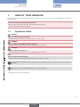
About this manual
This manual describes the entire life cycle of the device. Please keep this manual in a safe place, accessible to all users and
any new owners.
This manual contains important safety information.
Failure to comply with these instructions can lead to hazardous situations.
• This manual must be read and understood.
1.1.
Symbols used
danger
Warns you against an imminent danger.
• Failure to observe this warning can result in death or in serious injury.
WARNING
Warns you against a potentially dangerous situation.
• Failure to observe this warning can result in serious injury or even death.
CAUTION
Warns you against a possible risk.
• Failure to observe this warning can result in substantial or minor injuries.
NOTE
Warns you against material damage.
• Failure to observe this warning may result in damage to the device or system.
Indicates additional information, advice or important recommendations for your safety and for the correct operation of
the device.
Refers to information contained in this manual or in other documents.
→→Indicates a procedure to be carried out.
5
english
Type 8619
Intended use
2.
Intended use
Use of this device that does not comply with the instructions could present risks to people, nearby installations and
the environment.
• The device is intended, depending on the modules fitted and the measurement sensors connected, for the acquisition,
processing, transmission and regulation of physical parameters such as pH, conductivity, temperature or flow rate... .
• This device must be protected against electromagnetic interference, ultraviolet rays and, when installed outdoors, the effects
of climatic conditions.
• This device must be used in compliance with the characteristics and commissioning and use conditions specified in the
contractual documents and in the user manual.
• Requirements for the safe and proper operation of the device are proper transport, storage and installation, as well as careful
operation and maintenance.
• Only use the device as intended.
2.1.
Restraints
Observe any existing restraints when the device is exported.
2.2.
Foreseeable misuse
• Do not use this device in explosive atmospheres.
• Do not use this device in an environment incompatible with the materials from which it is made.
• Do not make any external modifications to the device such as for instance painting or varnishing any part of the device.
• Do not power the device with an AC voltage or a DC voltage higher than 36VDC.
6
english
Type 8619
Basic safety information
3.
Basic safety information
This safety information does not take into account:
• any contingencies or occurrences that may arise during assembly, use and maintenance of the device.
• the local safety regulations that the operator must ensure the staff in charge of installation and maintenance observe.
Danger due to electrical voltage.
• Shut down and isolate the electrical power source before carrying out work on the system.
• Observe all applicable accident protection and safety regulations for electrical equipment.
Various dangerous situations.
To avoid injury take care to:
• prevent any power supply switch-on.
• carry out the installation and maintenance work by qualified and skilled staff with the appropriate tools.
• guarantee a set or controlled restarting of the process after a power supply interruption.
• use the device only if in perfect working order and in compliance with the instructions provided in the user manual.
• observe the general technical rules during the planning and use of the device.
NOTE
Elements / Components sensitive to electrostatic discharges
• This device contains electronic components sensitive to electrostatic discharges. They may be damaged if they are touched
by an electrostatically charged person or object. In the worst case scenario, these components are instantly destroyed or
go out of order as soon as they are activated.
• To minimise or even avoid all damage due to an electrostatic discharge, take all the precautions described in the
EN 100 015-1 norm.
• Also ensure that you do not touch any of the live electrical components.
This device was developed with due consideration given to accepted safety rules and is state-of-the-art. However, risks
may arise.
Failure to observe these instructions as well as any unauthorised work on the device excludes us from any liability and also
nullifies the warranty which covers the device and its accessories.
7
english
Type 8619
General information
4.
General information
4.1.
Contents of the delivery
When you receive the merchandise, make sure that the contents of the delivery have not been damaged in any way and
ensure that they correspond exactly with the delivery note or packing list. If this is not the case, contact your retailer
immediately.
The addresses of our international branches can be found on the last pages of this manual. They can also be found on the
Bürkert
Company
Locations.
Internet under: www.burkert.com
4.2.
Warranty conditions
The condition governing the legal warranty is the conforming use of the 8619 type multiCELL in observance of the operating
conditions specified in this manual.
The terms and conditions of any warranty are governed by our general terms and conditions of sale.
The legal warranty only covers possible defects in the 8619 type multiCELL and its components.
Bürkert cannot be held responsible for any losses or damage related to the product, the service, this warranty or other,
including financial or intangible losses, the price paid for the product, a loss of profits, revenues, data, enjoyment or use
of the product or of any related product, or indirect or fortuitous loss or damage.
In the event of differences in interpretation and understanding of this chap. 4.2, the French version alone shall prevail.
4.3.
Information on the Internet
You can find the user manuals and technical data sheets regarding the type 8619 at:
www.burkert.com
Documentation
Datasheets or Manuals/Approvals
Type 8619
The complete manual in 3 languages (French, English, German) can be ordered under code: 561096.
8
english
Type 8619
Description
5.
Description
5.1.
Area of application
The 8619 multiCELL is a multifunction device intended to display, transmit and regulate various physical parameters. It can be
used, for example, to manage a water treatment system (a boiler, a cooling tower or a reverse osmosis system).
5.2.
General description
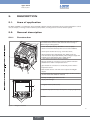
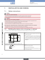
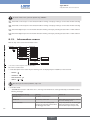
5.2.1.
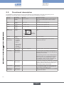
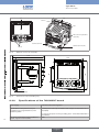
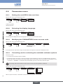
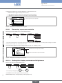
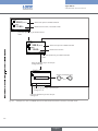
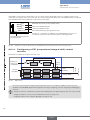
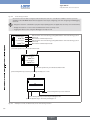
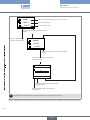
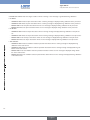
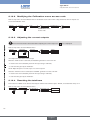
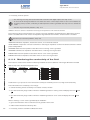
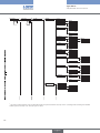
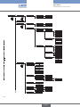
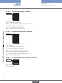
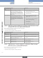
Construction
A
A: standardised 1/4 DIN housing (92x92 mm) with seal, to be built
into and attached to the door of the electrical switch housing or
cabinet using 4 locking systems.
B: a main board (identified by "M0:MAIN" on the rear plate) :
• used to connect the electrical power source of the multiCELL;
• used to power another device, e.g. a flow-rate sensor;
• offering 2 digital inputs (identified by "DI", digital input), two
4-20 mA current outputs (identified by "AO", analogue output) and
2 digital outputs (identified by "DO", digital output).
C: 1 to 6 slots for placing the following modules:
B
• light grey module for connection of a pH or oxidation reduction
potential sensor and/or a temperature sensor
• green module for connection of a conductivity sensor and/or a
temperature sensor
E
C
D
• black module with two 4-20 mA current outputs and 2 digital
outputs.
D: functional ground screw (connected internally to all "FE" terminals
on the main board and additional modules).
E: memory card (SD type) reader/recorder
F: display with backlight.
F
G
G: navigation button (4 directions).
H: 4 dynamic keys (function keys with dynamic changing assignment).
J: 2 LEDs.
H
J
Fig. 1:
Design of an 8619
9
english
Type 8619
Description
5.3.
Functional description
The multiCELL is used to link each input to a function (dosing, for example) which can be fully configured by the user.
Depending on the selected model, the following functions are offered as standard or as options:
Function
Arithmetic
Availability
Standard on all
models
Formula
A+B, A-B, A/B
PASS
Standard on all
models
Standard on all
models
Standard on all
models
Standard on all
models
A/B x 100%
Example for usage
Arithmetic procedure between 2 values with the
same unit. A or B may be the result of another
function.
Calculation of the passage rate.
(1 - A/B) x 100%
Calculation of the rejection rate.
(A/B - 1) x 100%
Calculation of the deviation rate.
100 %
Calculation of an output proportionally to bounded
input.
REJECT
DEVIAT
PROP
(proportional)
0%
scalON/OFF
Flow rate
measurement
PID
Time dosing
Standard on all
models
• Standard
on models
560205 or
560213
• Optional (see
chap. 9.9.4)
on all the
other models
Optional (see
chap. 9.9.4)
Optional (see
chap. 9.9.4)
Volume dosing
Optional (see
chap. 9.9.4)
Concentration
Optional (see
chap. 9.9.4)
Datalogger on
memory card
Optional (see
chap. 9.9.4)
scal+
ON/OFF control
process
parameter
For all input types.
Each of the 2 digital inputs can be used to
measure the flow rate.
Continuous regulation
For all input types; with internal or external setpoint.
In a cooling tower, for example; used to dose 2
products at fixed intervals or for twice daily dosing
scheduled over one week. The time dosing function can be combined with an
ON/OFF function on a conductivity measurement
only, in order to ensure prebleed of the system.
The "ON/OFF" function must be configured and
activated before the time dosing function.
Dedicated to cooling towers. Metering of a specific
volume of water and activation of an actuator during
a specific period in order to add a product, and
finally reset the water volume to zero.
The concentration graphs for certain compounds
such as NaCl and H2SO4 are memorised for use
over the entire concentration range.
Option to memorise the variations in 1 to 16 values
in a given time interval.
10
english
Type 8619
Description
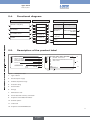
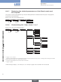
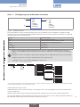
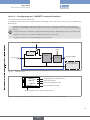
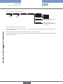
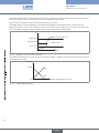
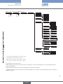
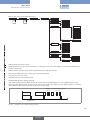
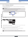
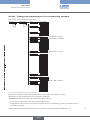
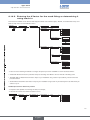
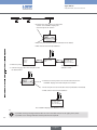
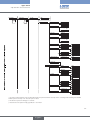
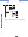
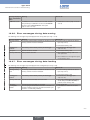
5.4.
Functional diagram
Inputs
Control functions
Outputs
Function 1
"On/off" or frequency
Output
Function 2
Conductivity sensor (2 or 4
electrodes)
Function 3
pH / Redox sensor
Function 4
Temperature sensor, Pt100 or
Pt1000
Function 5
analog outputs:
4...20 mA x
4...20 mA
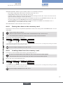
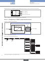
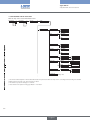
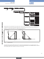
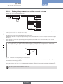
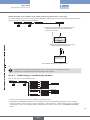
Description of the product label
8619 multiCELL
Supply: 12-36VDC
Temp: -10...+60 °C
IP65 PANEL (FRONT) IP20 (REAR)
S-N:1110
1
2
3
4
5
00560204
6
W44ML
Made in France
Made in France
PWM or "on/off" or
PFM or pulse or status
like alarms
Memory card
7
12
Fig. 2:
digital outputs:
transistor x
Display
Function 6
5.5.
Signal
Main: 2xDI - 2xAO - 2xDO - SD CARD
M1: pH/ORP - PT100/1000
M2: RES COND 2/4 POLES PPT100/1000
M3: 2xAO - 2xDO
M4:
M5:
M6:
Softw.:
00560204
W44ML
}
8
9
10
11
Example of a label
1. Type of device
2. Electrical power supply
3. Ambient temperature range
4. Protection rating
5. Serial number
6. EC logo
7. Manufacturer code
8. Device fitted with a memory card reader
9. Properties of the additional modules
10. Software options
11. Order code
12. Properties of the M0:MAIN board
11
english
Type 8619
Description
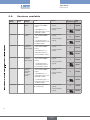
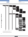
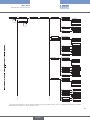
5.6.
Supply
voltage
12-36 VDC
12-36 VDC
12-36 VDC
12-36 VDC
12-36 VDC
12-36 VDC
Versions available
M0:MAIN Additional
board
modules
fitted
1 "pH/ORP"
module
fitted
fitted
fitted
fitted
fitted
Inputs
Outputs
• 2 "DI" digital inputs ("on/
off") on the M0:MAIN
board
• 2 4-20 mA "AO"
outputs
• 2 "DO" transistor
• 1 pH/ORP input + 1
outputs
temperature input, on the
"pH/ORP" module
1 "COND"
• 2 "DI" digital inputs ("on/ • 2 4-20 mA "AO"
module
off") on the M0:MAIN
outputs
board
• 2 "DO" transistor
• 1 conductivity input + 1
outputs
temperature input, on the
"COND" module
2 "pH/ORP"
• 2 "DI" digital inputs ("on/ • 4 4-20 mA "AO"
modules + 1
off") on the M0:MAIN
outputs
"OUT" module
board
• 4 "DO" transistor
outputs
• 1 pH/ORP input + 1
temperature input, on
each "pH/ORP" module
2 "COND"
• 2 "DI" digital inputs ("on/
modules + 1
off") on the M0:MAIN
"OUT" module
board
1 "pH/ORP"
module +
1 "COND"
module
+ 1 "OUT"
module
-
• 1 conductivity input +
1 temperature input on
each "COND" module
• 2 "DI" digital inputs ("on/
off") on the M0:MAIN
board
• 1 pH/ORP input + 1
temperature input on the
"pH/ORP" module
• 1 conductivity input + 1
temperature input on the
"COND" module
2 "DI" digital inputs ("on/
off" or frequency)
UL Order
recognized code
no
560208
yes
no
560201
560209
yes
no
560202
560210
yes
• 4 4-20 mA "AO"
outputs
560200
no
• 4 "DO" transistor
outputs
560203
560211
yes
• 4 4-20 mA "AO"
outputs
no
• 4 "DO" transistor
outputs
560212
yes
• 2 4-20 mA "AO"
outputs
• 2 "DO" transistor
outputs
12
english
no
yes
560204
560205
560213
Type 8619
Technical data
6.
Technical data
6.1.
Conditions of use
Ambient temperature:
-10… +60°C (operating)
restricted to 0 ... +60°C, if a memory card is used
Air humidity:
< 85%, non condensated
Protection rating:
IP65 and NEMA4X (on front, once built in, housing closed)
IP20 (non front parts inside the housing)
6.2.
Compliance to standards and directives
• EMC: EN 61000-6-2 (2005), EN 61000-6-3 (2001)
• Vibration: EN 60068-2-6
• Shock: EN 60068-2-27
UL recognised devices (
the following standards:
) for the United States of America and Canada with variable key PE72 also comply to
• UL 61010-1
• CAN/CSA-C22.2 n° 61010-1
6.3.
General technical data
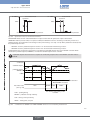
6.3.1.
Mechanical data
Mechanical data
Built in and locking system / seal
Material
PPO / silicone
Front cover, upper layer, and keys / front cover,
sublayer, and display
Rear plate
Silicone / PC
Terminal blocks
PBT, contacts in gold-plated copper alloy
Ground screw + spring washer
Stainless steel 316 (A4)
Stainless steel 304
13
english
Type 8619
Technical data
PC
PC
Silicone
PPO
PBT, contacts in gold-plated
copper alloy
Stainless steel 304
Stainless steel 316 (A4)
Silicone
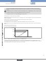
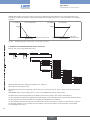
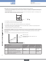
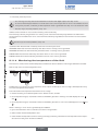
Fig. 3:
Materials used for the multiCELL
112
102
107
101
55
11
max. 4 mm
112
(wall thickness)
Fig. 4:
Dimensions of the multiCELL [mm]
6.3.2.
14
Specifications of the "M0:MAIN" board
Power supply
12-36 VDC, filtered and regulated
Specifications of the power source (not
provided) of UL-recognised devices, with
variable key PE72
• Limited power source (in accordance with chap. 9.3 of the UL 61010-1
standard)
Max. power consumption (without additional
module, outputs not connected)
• or class 2 type power source (according to the 1310/1585 and 60950-1
standards)
1.5VA
english
Type 8619
Technical data
Power distribution ("PWR OUT")
12-36 VDC, 1.8A max.
All digital inputs ("DI")
• Voltage: 5-36VDC
• Input impedance: 3kW
• Galvanically insulated
• Protected against polarity reversal and voltage spikes
• Frequency: 0.5 to 2500Hz
• 4-20mA current
All analogue outputs ("AO")
• Any connection mode, in sink or source mode
• Galvanically insulated
• Protected against polarity reversal
• Max. loop impedance: 1100W at 36VDC, 610W at 24VDC, 100W at
12VDC
• Transistor
All digital outputs ("DO")
• Connection mode unimportant in NPN or PNP mode
• Galvanically insulated
• Protected against short circuits
• Max. voltage: 36VDC
• max. 700mA if one transistor is connected but max. 1A for both transistors connected
• Max. frequency: 2000Hz
• Per detachable 21-point set-screw connector, orange
Electrical connection
• Refer to chap. 6.3.6 for the specifications of the connection cables
Flow rate measurement (software option)
6.3.3.
Refer to the user manual for the flow sensor connected to the 8619
Specifications of the "pH/redox" module
pH measurement
• pH measurement range
• -2.00...+16.00
• Resolution of pH measurement
• 0.01pH
• Accuracy of pH measurement
• 0.02pH
• Potential difference measurement range
• -600...+600mV
• Resolution of potential difference measurement
• 0.1mV
• Accuracy of potential difference measurement
• 1mV
• pH probe type
Current consumption
• Electrochemical
0.1VA
15
english
Type 8619
Technical data
Measurement of the oxidation reduction
potential
• Oxidation reduction potential measurement range • -2000 ... +2000mV
• Resolution of the potential difference
measurement
• 0.1mV
• Accuracy of potential difference measurement
• 1mV
• Oxidation reduction potential probe type
Temperature measurement
• Electrochemical
• Measurement range
• -25°C ... +130°C
• Measurement resolution
• 0.1°C
• Measurement accuracy
• 1°C
• Temperature sensor type
Electrical connection
• Pt100 or Pt1000, with 2 or 3 wires
• Per detachable 9-point set-screw connector, grey
• Refer to chap. 6.3.6 for the specifications of connection cables
6.3.4.
Specifications of the "COND" conductivity module
Conductivity measurement
• Measurement range
• 0.000 µS/cm...2000 mS/cm
• Measurement resolution
• 10-9S/cm
• Measurement error
• < 0.5% of measured value + sensor error
• Conductivity cell type
• With 2 or 4 electrodes; the specifications of Bürkert cells are
described in the relevant manual.
Resistivity measurement
• Measurement range
• 0.500Wcm...2.000MW/cm
• Measurement resolution
• 10-1Wcm
• Measurement error (without sensor)
• < 0.5% of measured value
0.25VA
Current consumption
Temperature measurement
• Measurement range
• -40°C ... 200°C
• Measurement resolution
• 0.1°C
• Measurement error
• 1°C
• Temperature sensor type
Electrical connection
• Pt100 or Pt1000, with 2 or 3 wires
• Per detachable 9-point set-screw connector, green
• Refer to chap. 6.3.6 for the specifications of the connection cables
16
english
Type 8619
Technical data
6.3.5.
Specifications of the additional "OUT" outputs board
Current consumption
0.1VA
All digital outputs ("DOx")
• Transistor
• Any connection mode, in NPN or PNP mode
• Galvanically insulated
• Protected against short circuits
• Max. voltage: 36VDC
• max. 700mA per transistor but max. 1A if both transistors are connected
All analogue outputs ("AOx")
• Max. frequency 2000Hz
• 4-20mA current
• Any connection mode, in sink or source mode
• Galvanically insulated
• Protected against polarity reversal
Electrical connection
• Max. loop impedance: 1100W at 36VDC, 610W at 24VDC, 100W at
12VDC
• Per detachable 9-point set-screw connector, black
• Refer to chap. 6.3.6 for the specifications of the connection cables
6.3.6.
Specifications of the connection cables
• Use shielded cables for the electrical connection.
• Be sure to use cables in which the wires present the specifications described in the table below.
Wire specifications
Dimensions of the max. clamping area
• Single core H05(07) V-U
0.2...1.5 mm2
• Flexible wire H05(07) V-K
0.2...1.5 mm2
• With non-insulated end connection
0.2...1.5 mm2
• With insulated end connection
0.2...0.75 mm2
Table 1 :
Specifications of the wires making up the connection cables
17
english
Type 8619
Installation and wiring
7.
Installation and wiring
7.1.
Safety instructions
danger
Risk of injury due to electrical discharge.
• Shut down and isolate the electrical power source before carrying out work on the system.
• Observe all applicable accident protection and safety regulations for electrical equipment.
WARNING
Risk of injury due to non-conforming installation.
• Electrical installation can only be carried out by qualified and authorised personnel with the appropriate tools.
• Install appropriate safety devices (correctly rated fuse and/or circuit-breaker).
• The use of probes/sensors sold by Bürkert is preferable.
• Follow the instructions on installation and wiring of remote sensors connected to the multiCELL.
Risk of injury due to unintentional switch on of power supply or uncontrolled restarting of the installation.
• Take appropriate measures to avoid unintentional activation of the installation.
• Guarantee a set or controlled restart of the process subsequent to the installation of the device.
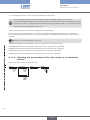
7.2.
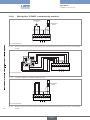
Building the device into a housing or cabinet
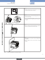
→→Follow the instructions below to build the multiCELL delivered fully assembled, into a housing or cabinet.
Stage 1:
92 +0,5/-0
5
→→Check that the thickness of the door of the housing or
5,5
10
5,5
92 +0,5/-0
cabinet is 4 mm max.
→→Cut out the hole in the door of the electrical housing
or cabinet in accordance with the standard, IEC
61554:1999 (DIN 43700) , allowing the space
required around the cut-out and inside the cabinet to
easily handle the 4 locking systems, delivered with the
multiCELL.
This diagram is not to scale. The dimensions are given in mm.
Body
Stage 2:
Prepare the 4 locking systems:
x4
Screw
→→Insert a screw into each device.
→→Tighten the screw until the end of the shaft of the screw
is flush with the device.
18
english
Type 8619
Installation and wiring
Stage 3:
→→Slide the housing into the cut-out with the connectors
to the back until it can go no further.
Stage 4:
→→Insert (1) the hooks on the first locking system into the
slots on the housing.
→→Pull the locking system (2) until you hear a click. The
1
2
click may be heared when tightening the locking system
at stage 6.
Stage 5:
→→Place the locking system flush against the multiCELL
by hand, so that the hooks remain in place.
Stage 6:
→→Fully
tighten the screws using an appropriate
screwdriver.
→→Repeat
stages 4 to 6 to fit the other 3 locking
systems.
Fig. 5:
Insertion of the 8619 into a housing or cabinet
19
english
Type 8619
Installation and wiring
7.3.
Electrical wiring
danger
Risk of injury due to electrical discharge.
• Shut down and isolate the electrical power source before carrying out work on the system.
• Observe all applicable accident protection and safety regulations for electrical equipment.
• Use a high quality electrical power supply (filtered and regulated).
• Connect the functional earth on the installation to the ground screw on the device (see Fig. 1)
• Connect the shielding on each wire to an "FE" (functional earth) terminal to guarantee the equipotentiality
of the installation.
• Use shielded cables that respect the specifications described in Table 1 : Specifications of the wires making
up the connection cables
7.3.1.
Electrical connections
For all versions of the multiCELL, the electrical connection is made by set-screw connectors.
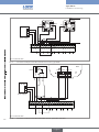
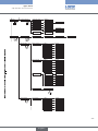
7.3.2.
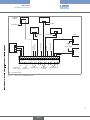
Wiring the M0:MAIN board
The M0:MAIN board is used to connect the multiCELL's electrical power source. It has:
• 2 digital inputs (marked DI1 and DI2), for connecting a flow sensor for example
• Two 4-20 mA analogue outputs (marked AO1 and AO2)
• 2 digital outputs (marked DO1 and DO2)
The inputs and outputs are galvanically insulated and therefore voltage free.
20
english
Type 8619
Installation and wiring
1st digital
output
1st 4-20 mA
+ 0 VDC
5-36 VDC
2nd digital
output
2nd 4-20 mA
+ -
+ -
Load 1
12-36 VDC
0 VDC
0 VDC
12-36 VDC
+
0 VDC
0 VDC
5-36 VDC
12-36 VDC
12-36 VDC
+
-
12-36 VDC
+
-
Power supply
0 VDC
Electrical
power supply
Power
distribution
DI2 FE AO1
Digital inputs
AO2 FE DO1
Analogue
outputs
T-
FE
T+
T-
FE
T+
I-
I+
I-
I+
FE
D-
D-
DI1
D+
FE
SUPPLY PWR OUT
D+
-
+
V-
FE
V+
Load 2
DO2 FE
Digital outputs
FE = functional earth
Fig. 6:
Wiring of the "M0:MAIN" board
21
english
Type 8619
Installation and wiring
PNP
1
1
NPN
V+
V+
12-36 VDC
3
3
2
+
2
0V
0V
SUPPLY PWR OUT DI1
DI2
AO2 FE DO1
T-
FE
T-
T+
FE
T+
I-
I-
FE AO1
I+
I+
FE
D-
DD+
FE
D+
+
-
V-
FE
V+
Power supply
DO2 FE
FE = functional earth
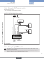
Fig. 7:
Connection example for the 8619 with two flow sensors, type 8030
X
8041
8071
T+
T+
white
black
5 6
red
3 4
1 2
VDC
Pls- Pls+ PE V- V+ 4...20
12-36 VDC
+
DI1
DI2 FE AO1
AO2 FE DO1
FE = functional earth
22
Fig. 8:
Connection example for the 8619 with 2 flow sensors, types 8071 and 8041
english
T-
FE
T-
I-
FE
I+
I-
I+
D-
FE
D+
FE
SUPPLY PWR OUT
D+
D-
-
+
FE
V-
V+
Power supply
DO2 FE
Type 8619
Installation and wiring
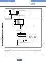
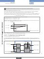
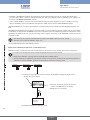
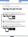
7.3.3.
Wiring the "OUT" outputs module
Wiring the "OUT" outputs module:
• Two 4-20 mA analogue outputs (marked AO1 and AO2);
• Two digital outputs (marked DO1 and DO2).
The outputs are galvanically insulated, and therefore voltage free.
1st 4-20 mA
+ 0 VDC
2nd 4-20 mA
+ Load 1
12-36 VDC
12-36 VDC
0 VDC
12-36 VDC
0 VDC
+
-
12-36 VDC
+
-
1 2
3
Analogue
outputs
6
Load 2
T-
T+
T-
FE
4 5
T+
I-
I+
I-
I+
0 VDC
7 8
9
Digital outputs
FE = functional earth
Fig. 9:
Wiring the "OUT" outputs module
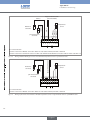
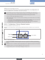
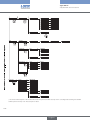
7.3.4.
Wiring the "pH/ORP" module
• Wire a pH/redox sensor in symmetrical mode to obviate the influence of interference and, in this case, wire the
equipotential electrode (compulsory).
• When the pH/redox sensor is wired in asymmetrical mode, measurement of the pH or the oxidation reduction
potential may drift over time when the equipotential electrode is not wired.
23
english
Type 8619
Installation and wiring
Equipotential electrode
(recommended)
black (1)
Temperature
sensor
1 2
4 5
6
7 8
TS
TS
FE
CG
RE
3
GD
RE
ME
pH measurement
electrode
SE
brown (2)
white (2)
black (2)
blue (2)
translucid (1)
Reference
electrode
9
FE = functional earth
(1)
Colour of the wires in Bürkert connection cables for order codes 561904, 561905 or 561906.
(2)
Colour of the wires in the Pt1000 sensor for order code 427023 and its Bürkert connection cable for order code 427113.
Fig. 10:
Wiring a Bürkert 8200 type sensor and a Pt1000 temperature sensor in symmetrical mode
translucid (1)
Reference
electrode
Equipotential electrode
black (1)
Temperature
sensor
7 8
TS
TS
6
SE
4 5
GD
FE
3
CG
1 2
RE
RE
ME
pH measurement
electrode
9
FE = functional earth
(1)
Colour of the wires in Bürkert connection cables for order codes 561904, 561905 or 561906.
Fig. 11:
Wiring a pH sensor and a Pt100 or Pt1000 temperature sensor in asymmetrical mode to a pH/ORP module
24
english
Type 8619
Installation and wiring
Temperature
sensor
Oxidation reduction potential
measurement electrode
6
TS
4 5
TS
FE
3
SE
CG
RE
1 2
GD
RE
ME
Reference
electrode
7 8
9
FE = functional earth
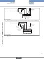
Fig. 12:
Wiring an oxidation reduction potential sensor and a Pt100 or Pt1000 temperature sensor in a pH/ORP module
Oxidation reduction potential
measurement electrode
Temperature
sensor
Reference
electrode
7 8
TS
6
TS
4 5
SE
3
FE
CG
GD
1 2
RE
RE
ME
pH measurement
electrode
9
FE = functional earth
Fig. 13:
Wiring a pH sensor, an oxidation reduction potential sensor and a Pt100 or Pt1000 temperature sensor in a pH/
ORP module
25
english
Type 8619
Installation and wiring
7.3.5.
Wiring the "COND" conductivity module
Conductivity
sensor
TS
6
TS
FE
4 5
SE
3
GD
P-
1 2
C-
P+
C+
Temperature
sensor
7 8
9
FE = functional earth
Fig. 14:
Wiring a resistive conductivity cell with 2 electrodes and a Pt100 or PT100 temperature sensor in a conductivity
module
1
8220
7 8
TS
6
TS
4 5
FE
3
SE
GD
C-
1 2
P-
P+
2
C+
3
9
FE = functional earth
Fig. 15:
Connection example for a 8220 conductivity sensor
7 8
TS
TS
6
SE
4 5
C-
FE
3
GD
1 2
P-
P+
C+
Temperature
sensor
9
FE = functional earth
Fig. 16:
26
Wiring a resistive conductivity cell with 4 electrodes and a Pt100 or PT100 temperature sensor in a conductivity
module
english
Type 8619
Commissioning
8.
Commissioning
8.1.
Safety instructions
WARNING
Danger due to non-conforming commissioning.
Non-conforming commissioning could lead to injuries and damage the device and its surroundings.
• Before commissioning, make sure that the staff in charge have read and fully understood the contents of the manual.
• In particular, observe the safety recommendations and intended use.
• The device/installation must only be commissioned by suitably trained staff.
Protect this device against electromagnetic interference, ultraviolet rays and, when installed outdoors, the
effects of the climatic conditions.
27
english
Type 8619
Adjustment and functions
9.
Adjustment and functions
9.1.
Safety instructions
WARNING
Risk of injury due to non-conforming adjustment.
Non conforming adjustment could lead to injuries and damage the device and its environment.
• The operators in charge of adjustment must have read and understood the contents of this manual.
• In particular, observe the safety recommendations and intended use.
• The device/installation must only be adjusted by suitably trained staff.
9.2.
Functions
The device has 2 modes of use:
Read mode
See chap. 9.7 for the description of Read mode.
Configuring Mode
This mode comprises 5 menus:
Menu title
"Parameters": see chap. 9.9
Relevant icon
This is
when the
device is being parametered............
....................
"Calibration": see chap. 9.10
"Diagnostics": see chap. 9.11
"Tests": see chap. 9.12
"Information": see chap. 9.13
28
english
Type 8619
Adjustment and functions
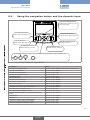
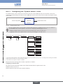
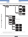
9.3.
Using the navigation button and the dynamic keys
The arrows displayed show
the directions in which you can
browse in this view.
To activate the dynamic
function to the far left, press
F1
MENU ABORT
F1
F2
SAVE
OK
F3
F4
LED A: shows the
system status. See chap. 10
To activate the dynamic
function to the far right, press F4
LED B: shows the sensor
status. See chap. 10.
To activate the second
dynamic function, press F2
To activate the third
dynamic function, press F3
The navigation button is used to move in 4 directions, symbolised throughout the manual by
and
Fig. 17:
.
Using the navigation button and the dynamic keys
You want to...
Press...
....access the Configuring mode
Dynamic function, "MENU", from any view in Read mode
...go back to Read mode
...access the menu displayed
...access the highlighted function
...confirm the enter
...save modifications
...go back to the parent menu
...cancel the current operation
...set a setpoint value
...activate manual mode in a configured and activated function
...manually set the percentage of the function
...force the result of a function to 0%
...force the result of a function to 100%
...activate automatic mode in a configured and activated
function
...start teach-in
...end teach-in
...answer the question asked in the affirmative
...answer the question asked in the negative
...select the highlighted character or mode
Dynamic function, "MEAS"
Dynamic function, "OK"
Dynamic function, "OK"
Dynamic function, "OK"
Dynamic function "SAVE"
Dynamic function "BACK"
Dynamic function "ABORT"
Dynamic function "SETP"
Dynamic function "MANU"
Dynamic function "CMD"
Dynamic function "0%"
Dynamic function "100%"
Dynamic function "AUTO"
Dynamic function "START"
Dynamic function "END"
Dynamic function "YES"
Dynamic function "NO"
Dynamic function "SEL"
29
english
Type 8619
Adjustment and functions
You want to...
Press...
...browse in Read mode
next view
previous view
next level
previous level
...browse in the Configuring mode menus
display the next
display the previous
menu
menu
highlight the next
function function
increase the
percentage
reduce the
percentage
...browse in the menu functions
highlight the previous
...set the contrast or brightness percentage for the display
(after accessing the function in the "Parameters" menu)
...modify a numerical value or the units
increment the figure
selected or modify the units
decrement the figure selected
or modify the units
select the next
figure
select the previous
figure
...allocate the "+" or "-" sign to a numerical value
to the extreme left of the numerical value then
until the desired sign is displayed
...move the decimal point in a numerical value
to the extreme right of the numerical value then
until the decimal point is in the desired place
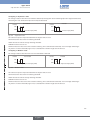
9.4.
Modifying a name
This chap. describes how to use the keyboard displayed to modify the name of a process variable (13 characters max.), a
function (12 characters max.) or the title of a view (12 characters max.).
To retrieve the original name, even after modification and saving:
→→edit the new name
→→delete all the characters using one of the methods described on p. 32.
30
english
Type 8619
Adjustment and functions
Example: rename a variable (choose one of the variables suggested).
Refer to chap. 9.8 to access Parameters menu. Parameters
This is
when the
device is being parametered............
....................
Display
PV names
M0:MAIN
DI1:Flow
Edit name
This is
when the
device is being parametered............
....................
→→Place the cursor over the desired letter, using the navigation button:
→→Select the highlighted letter by pressing the key
(function "SEL"):
F3
Enter name
_
_f
a bc
mn o
y z0
, ; .
d
p
1
?
ef ghi
qr st u
23456
! +- *
UPP
ABORT
j kl
v wx
789
/ <>
ovr
SEL SAVE
F3 F4
→→Display the capital letters and different signs by placing the cursor over "UPP" then pressing the key
"SEL"):
F3
(function
Enter name
_
_f
A BC
M NO
YZ (
^ %_
D E FG H I J K L
P Q RS T U V W X
) { } [ ]@ # $ &
' " | ~
low
ovr
ABORT
SEL SAVE
F3 F4
→→By default, the "character insertion" ("Ins") mode is activated; to activate the "character overwrite" mode, place the cursor
over "ovr" then press the key
F3
(function "SEL"):
Enter name
_
_f
a bc
mn o
y z0
, ; .
ABORT
d
p
1
?
ef ghi
qr st u
23456
! +- *
UPP
j kl
v wx
789
/ <>
Ins
SEL SAVE
F3 F4
31
english
Type 8619
Adjustment and functions
→→to select a character in the entered name, place the cursor over the arrows
or
and press the key
(function "SEL"):
F3
Enter name
____
flow
____
a bc
mn o
y z0
, ; .
d
p
1
?
ef ghi
qr st u
23456
! +- *
UPP
ABORT
j kl
v wx
789
/ <>
ovr
SEL SAVE
F3 F4
→→to delete the character selected in the entered name, place the cursor over
"SEL"):
and press the key
F3
(function
Enter name
____
flow
____
a bc
mn o
y z0
, ; .
d
p
1
?
ef ghi
qr st u
23456
! +- *
UPP
ABORT
j kl
v wx
789
/ <>
ovr
SEL SAVE
F3 F4
→→to delete the character preceding the character selected in the entered name, place the cursor over and press the key
F3
(function "SEL"):
Enter name
__
fw
__
a bc
mn o
y z0
, ; .
ABORT
d
p
1
?
ef ghi
qr st u
23456
! +- *
UPP
j kl
v wx
789
/ <>
ovr
SEL SAVE
F3 F4
32
english
Type 8619
Adjustment and functions
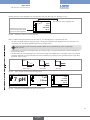
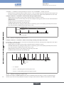
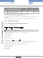
9.5.
Entering a numerical value
• Access, for example, the manual calibration function for a conductivity sensor. Refer to chap. 9.8 to access "Calibration"
menu.
Calibration
Mx:Conductivity
Cond manual calib
Cond. calib.
After confirming the numerical value
input by pressing "OK", modify the
4.294 S/cm
25.01 °C
2
Move the decimal point by
unit selected by pressing
0.000
µS/cm
or
pressing
to the far
right of the numerical value and
Increment or decrement the figure selected by
then on
until the
decimal point is in the desired
place (the decimal point moves
in a loop)
Fig. 18:
or
pressing
Example of a numerical value entering
• Access, for example, the pH value simulation function. Refer to chap. 9.8 to access "Tests" menu.
Tests
Simulate PV
PV:
M1:pH/ORP
Value:
INPUT
pH
Simulation value
Select the character to the far left by pressing
and then allocate the "+" or "-" sign by
pressing
T
- 1.000pH
.
To exit the "Tests" menu, press the dynamic key, "ABORT"
Fig. 19:
Changing the sign of a numerical value
33
english
Type 8619
Adjustment and functions
9.6.
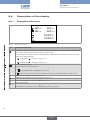
Description of the display
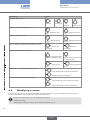
9.6.1.
Description of the icons
M0:MAIN
2010/06/29 13:40
OFF DI1
OFF DO1
OFF DI2
OFF DO2
X
SD
AO1
6.000 mA
AO2
20.00 mA
MENU
Fig. 20:
Icon
Position of the icons
Meaning and alternatives
Default icon when process monitoring is not activated via the "Diagnostics" menu; if monitoring is activated, this
icon indicates that the parameters monitored are not out of range.
If monitoring of the electrodes and/or the fluid temperature and/or the fluid conductivity are activated, the alternative icons in this position are:
•
, combined with
: see chap. 9.11.2 to 9.11.4
•
, combined with X : see chap. 9.11.2 to 9.11.4
Device currently measuring.
The alternative icons in this position are:
•
H
flashing: HOLD mode activated (see chap. 9.10.1)
• T flashing: running check that an output is working and behaving correctly (see chap. 9.12.2 to 9.12.3)
"Maintenance" event; see chap. 9.10.6 and 9.10.7
"Warning" event; see chap. 9.10.6, 9.10.7 and 9.11.2 to 9.11.4
X
Error" event; see chap. 9.10.6, 9.10.7 and 9.11.2 to 9.11.4
SD
Memory card inserted.
The alternative to this position is the icon X indicating a memory card error.
34
english
Type 8619
Adjustment and functions
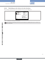
9.6.2.
Switching on the device for the first time
When switching on the device for the first time, the display shows the first view in READ mode:
M0:MAIN
2010/06/29 13:40
OFF DI1
OFF DO1
OFF DI2
OFF DO2
AO1
6.000 mA
AO2
20.00 mA
MENU
Fig. 21:
Display when switching on for the first time
When switched on subsequently, the last active view in the Read menu is displayed. See chap. 9.7 to browse in all
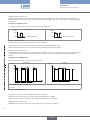
views in Read mode. 35
english
Type 8619
Adjustment and functions
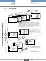
9.7.
Read mode
M6:Outputs
M2:Conductivity 2010/06/2913:40
M1:pH
2010/06/2913:40
M0:MAIN:
OFF
OFF
DI1
DI2
MENU
OFF DO1
OFF DO2
mA
6.000 AO1
mA
20.00 AO2
25 mS/cm
13:40
2010/06/2913:40
M0:MAIN:
L/s
6.53 pH
25.2 °C
0.500 DI1 39.20 mV
L
30.00 DI1
25.2 °C
L/s
1.000 DI2
L
33.00 DI2
........
MENU
2010/06/2913:40
OFF DO1
OFF DO2
mA
5.000 AO1
mA
12.00 AO2
Views of the modules connected to the device (cannot be modified):
• "M0:MAIN" view: displays the values of inputs and outputs on the main
board; the second "M0:" view is available on the devices with analysis
modules if the software option, "FLOW", is activated (see chap. 9.9.4)
• "M1:" to "M6:" views display the data for modules 1 to 6.
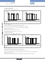
U4:PROCESS1 2010/06/29 13:40
1
3
U1:pH_COND
2
3
2010/06/29 13:40
25 mS/cm
6.53 pH
0
......
1
MENU
6.53
25
25.2
205
pH
mS/cm
°C
l/min
User defined views (U1 to U4) are
each used to display 1, 2 or 4 data or
a graph. Only the effectively defined
views are shown.
See chap. 9.9.8 to select the data to be
displayed.
MENU
F6:ONOFF
1
1
F2:PROP
2010/06/29 13:40
1 PV
250.2 µS/cm
F1:A+B
0
0
0
MENU
0
........
0
MENU SETP
0 CMD1
13.00 %
57 L/min
Off F3 Dos.St
Views of active functions which
cannot be modified (F1: to F6:) are
used to display one function each.
Only the views of functions declared
"active" are shown.
2010/06/29 13:40
L/min
148MENU
2010/06/29 13:40
µS/cm
250.0 PV
µS/cm
500.0 SP
%
0.00 CMD1
MANU
205 l/min
FlowProcess1
See chap. 9.9.11 to 9.9.15 to activate
the functions programmed and select
the data to be displayed.
36
english
Type 8619
Adjustment and functions
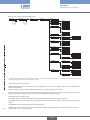
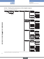
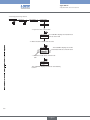
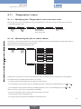
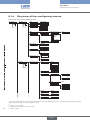
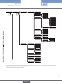
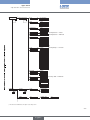
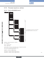
9.8.
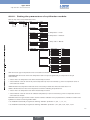
Configuring mode access
On any view in Read
mode, press
MENU
F1
Code
incorrect
This is
when the
device is being parametered............
....................
"Parameters"
code correct 1)
This is
when the
device is being parametered............
....................
Parameters
System
Display
Functions
Datalogger 2)
M0:Outputs
Mx:pH/ORP
Mx:Conductivity
Mx:Outputs
Parameters
OK
MEAS
F4
Code
incorrect
Calibration
Calibration
System
M0:Outputs
M0:Inputs
Mx:pH/ORP
Mx:Conductivity
Mx:Outputs
"Calibration" code
correct 1)
OK
MEAS
F4
Code
incorrect
Diagnostics
Diagnostics
System
Mx:pH/ORP
Mx:Conductivity
"Diagnostics"
code correct 1)
OK
MEAS
F4
Code
incorrect
Tests
"Tests"
code correct 1)
Tests
T
System
Simulate PV
M0:Outputs
Mx: Outputs
OK
MEAS
F4
Information
Information
MEAS
OK
Error
Warning
Maintenance
Smiley
System log
Versions
F4
1)
The code is not requested if the default code "0000" is used.
2)
This menu is available as an option (see chap. 9.9.4).
→→See chap. 9.14 for details of the functions per menu
english
37
Type 8619
Adjustment and functions
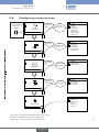
9.9.
Parameters menu
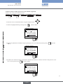
9.9.1.
Setting the multiCELL date and time
Refer to chap. 9.8 to access Parameters menu.
Parameters
System
This is
when the
device is being parametered............
....................
This is
when the
device is being parametered............
....................
Date
AAAA/MM/JJ
Time
HH:MMss
DATE: Set the date
TIME: Set the time
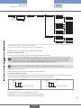
9.9.2.
Selecting the display language
Refer to chap. 9.8 to access Parameters menu.
Parameters
System
This is
when the
device is being parametered............
....................
Language
English
Français
This is
when the
device is being parametered............
....................
Deutsch
The messages are displayed in the new language as soon as the choice has been saved.
9.9.3.
Modifying the PARAMETERS menu access code
Refer to chap. 9.8 to access Parameters menu.
Parameters
System
This is
when the
device is being parametered............
....................
Code
0***
Confirm code
Enter the new
PARAMETERS menu
access code
This is
when the
device is being parametered............
....................
0***
Confirm the new
code
If the default access code "0000" is kept, the device does not request it to access the "Parameters" menu.
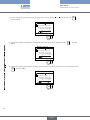
9.9.4.
Consulting and/or activating the available software options
This menu is used:
• to consult the list of software options available
• to activate the options by entering a code. The activation code is obtained on order from your Bürkert dealer: provide him
with the order code for your device, the product identifier and its serial number, which you will find in the "Information" menu
-> "Versions" -> "M0:MAIN" -> "Product ID" and "ProductSN"), specific to each device and each option.
The "Dosing" option also activates the "Flow" option if it does not exist by default in the device.
Refer to chap. 9.8 to access Parameters menu.
Parameters
This is
when the
device is being parametered............
....................
System
Software options
Available options
This is
when the
device is being parametered............
....................
Add new option
PID
Datalogger
Dosing
Flow
Concentration
INPUT
When an option is ticked, it is activated in the device.
38
english
Type 8619
Adjustment and functions
AVAILABLE OPTIONS : Read the options available, whether or not activated on the device:
-- PID: enables configuring of a PID function on the device; See chap. 9.9.14.
-- DATALOGGER: enables the saving of data; See chap. 9.9.18.
-- DOSING: enables configuring of the "Time dosing" and "Volume dosing" functions; See chap. 9.9.15 and 9.9.16. This
option automatically activates the "FLOW" option below.
-- FLOW: the "Flow" and "Totalizer" process inputs are available in the "PV" list on the "M0:MAIN" board (see chap. 9.15)
and use the digital inputs of the M0:MAIN board as inputs for themeasurement signals.
-- CONCENTRATION: the concentration tables for a number of solutions are available in the "Parameters" menu ->
"Mx:Conductivity" -> "Concentration" (see chap. 9.9.22)
ADD NEW OPTION : enter the activation code for an option.
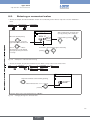
9.9.5.
Saving the data on the memory card
This function is used to save the user parameters ("Parameters" menu) on the memory card in the M0:MAIN board or on each
module fitted.
• Insert a memory card in the device.
• Data can only be saved if the "save data" function is deactivated. See chap. 9.9.4 and 9.9.18
• The software options activated on the device (see previous chap.) cannot be transferred.
Refer to chap. 9.8 to access Parameters menu.
Parameters
System
This is
when the
device is being parametered............
....................
Save settings
M0:MAIN
... 1)
This is
when the
device is being parametered............
....................
Mx:
The choices offered depend on the modules fitted and/or the options activated. See chap. 9.9.4. Consulting and/or activating the available
software options and chap. 9.15. Process inputs or values.
1)
If an error message is displayed, refer to chap. 10.3.6.
9.9.6.
Loading data from the memory card
This function is used to load data from the memory card, initially saved on it.
The device receiving the data must be identical to the one from which these data originate.
• Check that both devices have the same order code and the same activated software options. Refer to chap. 9.8 to access Parameters menu.
Parameters
This is
when the
device is being parametered............
....................
System
Load settings
This is
when the
device is being parametered............
....................
M0:MAIN
... 1)
Mx:
The choices offered depend on the modules fitted and/or the options activated. See chap. 9.9.4. Consulting and/or activating the available
software options and chap. 9.15. Process inputs or values.
1)
If an error message is displayed, refer to chap. 10.3.7.
39
english
Type 8619
Adjustment and functions
9.9.7.
Restoring the default parameters of the Read mode and
the outputs
This function is used to restore (dynamic key "Yes") the default parameters of the Read mode and outputs or keep (dynamic
key "No") the current parameters.
Refer to chap. 9.8 to access Parameters menu.
Parameters
System
This is
when the
device is being parametered............
....................
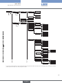
9.9.8.
Factory reset
M0:MAIN
... 1)
This is
when the
device is being parametered............
....................
Mx:
Customising the "User views 1 to 4"
Refer to chap. 9.8 to access Parameters menu.
Parameters
Display
This is
when the
device is being parametered............
....................
User view 1...4
Type:
None
1 line
This is
when the
device is being parametered............
....................
2 lines
4 lines
graph
Title:
INPUT
Line1...4:
PV:
M0:None
1)
... 2)
Mx :
Unit:
3)
Filter:
None
Fast
Slow
Period:
y min:
4)
4)
y max:
INPUT
INPUT
INPUT
4)
1)
If "Type" = 1, 2 or 4 "lines"
The choices offered depend on the modules fitted and/or the options activated. See chap. 9.9.4. Consulting and/or activating the available
software options and chap. 9.15. Process inputs or values.
2)
3)
The choices offered depend on the choice made in "PV" above
4)
If "Type" = "graph"
TYPE: Choosing to display 1, 2 or 4 values (on 1, 2 or 4 lines) or a graph in the customised "Ux" view selected.
40
english
Type 8619
Adjustment and functions
TITLE: Entering the name displayed in the corresponding "Ux" view. See chap. 9.4. Modifying a name.
U3:PROCESS1
2010/06/29 13:40
1
7 pH
1 S/cm
205 l/min
43 °C
3
0
Indicates the number of the
board or module from which
the process value originates.
Fig. 22:
1
The title of the view is displayed here.
MENU
Example of a title for a customised view
LINE1 to LINE4: Setting the parameters for the values (1, 2 or 4) displayed in a customised "Ux" view:
-- PV: Select the digital input, the analogue output or the physical parameter to be displayed on the line selected in this
customised view. The options available depend on the modules fitted.
One of the "PVs" in the conductivity module, available for the customised "Ux" views, is "USP" (see
chap. 9.9.22).
-- UNIT: Select the unit in which the digital input, the analogue output or the physical parameter selected is displayed on
the PV function above.
-- FILTER: Select the level of damping for the measurement signal on the digital input, the analogue output or the physical
parameter displayed on the line selected. Three levels of damping are proposed: "slow" (slow filtering has a high damping effect), "fast" or "none"
t
30 s
6s
"Slow" filter
Fig. 23:
MENU
Fig. 24:
150 ms
"Fast" filter
t
"No" filter
Types of filters and associated damping effects
U1:ph
1
t
2010/06/29 13:40
7 pH
U2:pH_COND
2010/06/29 13:40
3
U3:PROCESS1 2010/06/29 13:40
7 pH
1
1 S/cm
0
2
MENU
3
1
7 pH
1 S/cm
205 l/min
43 °C
MENU
Examples of customised views with 1, 2 and 4 lines
41
english
Type 8619
Adjustment and functions
LINE: Set the parameters for the graph displayed in a customised "Ux" view:
-- PERIOD: Enter the graph refresh period in seconds.
-- Y MIN: Enter the minimum value on the vertical axis for the PV selected.
-- Y MAX: Enter the maximum value on the vertical axis for the PV selected.
U1:Process1 2010/06/29 13:40
100.0°C
32.00°C
Ymax
Ymin
Fig. 25:
measured value of the process parameter
15.00°C
MENU
Example of a customised view of a graph
9.9.9.
Renaming a process variable
Renaming a process variable 9.8 to access Parameters menu.
Parameters
Display
This is
when the
device is being parametered............
....................
PV names
PV:M0:MAIN
M0:MAIN
M1:
This is
when the
device is being parametered............
....................
... 1)
Mx:
Edit name
INPUT
The choices offered depend on the modules fitted and/or the options activated. See chap. 9.9.4. Consulting and/or activating the available
software options and chap. 9.15. Process inputs or values.
1)
The entered name appears in the view in Read mode. See chap. 9.4. Modifying a name.
U4:PROCESS1
1
3
0
1
MENU
Fig. 26:
2010/06/29 13:40
pH
pHprocess1
6.53
25 mS/cm
25.2 °C
205 l/min
FlowProcess1
Default name of the process variable
Name entered for the process variable
Example of a renamed process variable
9.9.10. Setting the display contrast and brightness
Refer to chap. 9.8 to access Parameters menu.
Display
Param
This is
when the
device is being parametered............
....................
This is
when the
device is being parametered............
....................
→→Set each percentage using
Contrast
xx%
Brightness
xx%
and
.
CONTRAST: Choose the display contrast level (as a %).
42
BRIGHTNESS: Choose the light intensity of the display (as a %).
english
Type 8619
Adjustment and functions
9.9.11. Configuring an arithmetic function
A
A+B
A-B
A/B
(A/B)[%]
(1-A/B)[%]
(A/B-1)[%]
B
Fig. 27:
Fx : A+B
A-B
A/B
A/B[%]
(1-A/B)[%]
(A/B-1)[%]
Arithmetic functions
The functional block is used to calculate the image using one of the arithmetic functions available for 2 variables, A and B,
selected from the process variables available. Variables A and B must be of a kind and in identical units. Moreover, A and/or B
may be the result of a function already used:
Function
A+B
A-B
A/B
A/B[%]
(1 - A/B)[%]
(A/B - 1)[%]
Calculation made
Sum of 2 variables, A and B
Subtraction between the 2 variables, A and B
Ratio between the 2 variables, A and B
Passage rate
Rejection rate
Deviation rate
Once the function has been configured and activated, the result "Fx:" calculated is available in the list of process
variables on the "M0:MAIN" board. This list appears in the output configuring, user view configuring and datalogging
menus to:
• Assign the result "Fx:" calculated to a physical output (analogue, AO, or digital, DO) (see chap. 9.9.19 and 9.9.20).
• Display the result "Fx:" on one of the user defined "Ux" views: see chap. 9.9.8
• Logging the values of "Fx:" using the datalogger: see chap. 9.9.18
Refer to chap. 9.8 to access Parameters menu.
Parameters
This is
when the
device is being parametered............
....................
Functions
This is
when the
device is being parametered............
....................
F1...F6:
None
Type:
A+B
Name:
INPUT
A-B
Status:
ON
A/B
(A/B)[%]
(1-A/B)[%]
OFF
PV A: / PV B:
M0:MAIN M1:
(A/B-1)[%]
... 1)
Mx:
Filter:
None
Fast
Slow
The choices offered depend on the modules fitted and/or the options activated. See chap. 9.9.4. Consulting and/or activating the available
software options and chap. 9.15. Process inputs or values.
1)
TYPE: Indicates the function chosen.
NAME: Rename the function chosen. See chap. 9.4. Modifying a name . This name appears in the view associated with this
function in Read mode. STATUS: Used to activate (choose "ON") or deactivate (choose "OFF") the view of the function selected in Read mode.
PV A (or PV B): Combine a physical parameter (or the result of one of the functions, F1 to F6, already used) with variable A (or
B). Variables A and B must be of the same value type and have the same unit.
english
43
Type 8619
Adjustment and functions
FILTER: Choose the level of damping of the input variables. See Fig. 23: Types of filters and associated damping effects.
F1:A+B
148 L/min
Value of variable A
0
57 L/min
Value of variable B
0
205 L/min
MENU
Fig. 28:
2010/06/29 13:40
0
Result of the function A+B
Example of a view of an active arithmetic function in Read mode
9.9.12. Configuring a "PROP" proportional function
Configuring a "PROP" proportional function
System switch
100%
"PROP" function
fallback
position
Process
input (PV)
0%
scale-
Fig. 29:
Fx result: (CMD)
scale+
"PROP" proportional function
Refer to chap. 9.8 to access Parameters menu.
Parameters
This is
when the
device is being parametered............
....................
Functions
This is
when the
device is being parametered............
....................
F1...F6:
PROP
Type:
Name:
INPUT
Status:
ON
OFF
PV:
M0:MAIN
M1:
...
1)
Mx:
PV range:
PV filter:
PVScale-:
INPUT
PVScale+:
INPUT
None
Fast
Slow
Lim-
INPUT
Lim+:
INPUT
CMDSafe:
Mode
ON
OFF
Value
44
INPUT
The choices offered depend on the modules fitted and/or the options activated. See chap. 9.9.4. Consulting and/or activating the available
software options and chap. 9.15. Process inputs or values.
1)
english
Type 8619
Adjustment and functions
Once the function has been configured and activated, the result "Fx:" calculated is available in the list of process
variables on the "M0:MAIN" board. This list appears in the output configuring, user view configuring and datalogging
menus to:
• Assign the result "Fx:" calculated to a physical output (analogue, AO, or digital, DO) (see chap. 9.9.19 and 9.9.20).
• Display the result "Fx:" on one of the user defined "Ux" views: see chap. 9.9.8
• Logging the values of "Fx:" using the datalogger: see chap. 9.9.18
TYPE: Indicates the function chosen (here, "PROP").
NAME: Rename the function chosen. See chap. 9.4. Modifying a name . This name appears on the view associated with this
function in Read mode.
STATUS: Used to activate (choose "ON") or deactivate (choose "OFF") the function selected.
PV: Choose the process input for the function.
PV RANGE: Enter the minimum ("PVScale-" ) and maximum ("PVScale+") values of the process input.
PV FILTER: Choose the level of damping of the chosen process value. See Fig. 23: Types of filters and associated damping
effects.
LIM-: Enter the lower limit on the output.
LIM+: Enter the upper limit on the output.
Fx: CMD1
100%
Lim+
Lim0%
Fig. 30:
Scale-
Scale+
PV
Using the "LIM-" and "LIM+" parameters on a "PROP" function
CMD SAFE: Confirm (choose "Mode: ON") or do not confirm (choose "Mode:OFF") the use of a fallback position on the
output when the "System switch" event (see chap. 9.9.17) has the state "ON". When use of the fallback position is confirmed,
enter a fallback position value of between 0 and 100% for each output.
45
english
Type 8619
Adjustment and functions
F1:PROP
2010/06/29 13:40
1 PV
250.2 µS/cm
Value of the process variable selected
0 CMD1
13.00 %
MENU
Result of the function, in automatic mode
MANU
press this dynamic key to activate manual
mode
F1:PROP
1
0
2010/06/29 13:40
PV
250.2 µS/cm
Value of the process variable selected
CMD1
13.00 %
MENU
Result of the function
CMD AUTO
press this dynamic key to activate automatic
mode
press this dynamic key to set the percentage manually
This is
when the
device is being parametered............
....................
CMD1
Set the percentage using
12%
and
0% 100%
BACK
press this dynamic key to force the percentage to 100
press this dynamic key to force the percentage to 0
Fig. 31:
Examples of a view of a "PROP" function in Read mode and switch to manual or automatic mode
46
english
Type 8619
Adjustment and functions
9.9.13. Configuring an "ONOFF" control function
This function is used to set the on/off control.
A conductivity control system can be combined with the "time dosing" function (see chap. 9.9.15) to carry out a prebleed step
before dosing.
Once the function has been configured and activated, the result "Fx:" calculated is available in the list of process
variables on the "M0:MAIN" board. This list appears in the output configuring, user view configuring and datalogging
menus to:
• Assign the result "Fx:" calculated to a physical output (analogue, AO, or digital, DO) (see chap. 9.9.19 and 9.9.20).
• Display the result "Fx:" on one of the user defined "Ux" views: see chap. 9.9.8
• Logging the values of "Fx:" using the datalogger: see chap. 9.9.18
Setpoint (SP)
System
switch
prebleed
ONOFF
Process input
(PV)
fallback
position
result (Fx: CMD1)
"Time dosing"
function ("Dos. St.")
Fig. 32:
"ONOFF" function
F2:ONOFF
2010/06/29 13:40
µS/cm
1
250.0 PV
Value of the process variable chosen
1
500.0
Value of the setpoint
0
0
µS/cm
SP
%
CMD1
0.00
No Link F3 Dos.St
Result of the ONOFF function
No associated time dosing
MENU SETP
press this dynamic key to enter the setpoint value.
Fig. 33:
Example of a view of an "ONOFF" function in Read mode with no associated time dosing
47
english
Type 8619
Adjustment and functions
Refer to chap. 9.8 to access Parameters menu.
Parameters
This is
when the
device is being parametered............
....................
Functions
F1...F6:
ONOFF
This is
when the
device is being parametered............
....................
Type:
Name:
INPUT
Status:
ON
OFF
PV:
M0:MAIN
M1:
...
1)
Mx:
SP Value:
INPUT
PV range
PVScale-:
INPUT
PVScale+:
INPUT
PV filter:
None
Fast
Slow
Hysteresis
INPUT
Inversion
ON
OFF
MaxONtime:
Status:
ON
OFF
PreBleed:
Value
INPUT
Status:
ON
OFF
CMDSafe:
PB Limit ch1:
INPUT
PB Limit ch2:
INPUT
Mode
ON
OFF
Value
INPUT
The choices offered depend on the modules fitted and/or the options activated. See chap. 9.9.4. Consulting and/or activating the available
software options and chap. 9.15. Process inputs or values.
1)
TYPE: Indicates the function chosen.
NAME: Rename the function chosen. See chap. 9.4. Modifying a name. This name appears in the view associated with this
function in Read mode.
STATUS: Used to activate (choose "ON") or deactivate (choose "OFF") the function selected.
PV: Choose the process input for the function from the list suggested by the device. This process input may be a measured
physical parameter, an analogue output or the result of another active configured function.
SP VALUE: Enter the setpoint value.
PV RANGE: Enter the minimum ("PVScale-" ) and maximum ("PVScale+") values of the process input.
PV FILTER: Choose the level of damping of the chosen process value. See Fig. 23: Types of filters and associated damping
effects.
HYSTERESIS: Enter a hysteresis value for the switching point.
48
INVERSION: Used to invert (choose "ON") or not (choose "OFF") the operating direction of switching. See Fig. 34: Hysteresis mode, non-inverted and inverted.
english
Type 8619
Adjustment and functions
Fx: CMD1
non-inverted mode
hysteresis
Fx: CMD1
100%
100%
0%
Fig. 34:
inverted mode
hysteresis
0%
PV parameter
Setpoint
PV parameter
Setpoint
Hysteresis mode, non-inverted and inverted
MAXONTIME: Enter the max. authorised duration of output control: after this period, the output is deactivated.
PREBLEED: Define (choose "ON") or not (choose "OFF") the ONOFF function for controlling a conductivity function as a
prebleed function associated with a time dosing function ("Time Dosing": see chap. 9.9.15). When prebleed is activated, enter
the prebleed setpoint value:
-- PBLIMIT1: enter the prebleed setpoint for channel 1 on the associated "Time Dosing" function.
-- PBLIMIT2: enter the prebleed setpoint for channel 2 on the associated "Time Dosing" function.
Prebleed lowers the conductivity of the fluid to a value below the standard setpoint value of the ON/OFF controller. When
activated, the prebleed setpoint, "PBLIMITx", overrides the standard setpoint of the controller.
A prebleed setpoint value lower than or equal to the conductivity setpoint value of the ON/OFF controller must be
entered.
conductivity
standard setpoint
prebleed setpoint
"PBLIMITx"
t
CMD1
1
0
Title "Tdos state" (see Fig. 36)
change of status if "PBLIMIT" is reached or
"MAXONTIME" exceeded
"OFF"
"BLEED"
"ON"
"WAIT"
time dosing cycle, priority on the
controller
"OFF" : pending dosing
"BLEED" : prebleed currently underway
"ON" : dosing currently underway
"WAIT" : waiting time; see p.60
Fig. 35:
Combination of "ONOFF" and "TIME DOSING" functions on a conductivity measurement
49
english
Type 8619
Adjustment and functions
CMD SAFE: Confirm (choose "Mode: ON") or do not confirm (choose "Mode:OFF") the use of a fallback position on the
output when the "System switch" event (see chap. 9.9.17) has the state "ON". When use of the fallback position is confirmed,
enter a fallback position value of between 0 and 100% for each output.
F2:ONOFF
1
1
0
0
2010/06/29 13:40
µS/cm
250.0 PV
µS/cm
500.0 SP
%
0.00 CMD1
MENU SETP
Off F3 Dos.St
press this dynamic key to enter
the setpoint value.
Fig. 36:
Measured value of the process variable chosen
Value of the standard setpoint
result of the ONOFF function
Associated Time dosing; dosing status is "Off".
See Fig. 35: Combination of "ONOFF" and "TIME DOSING" functions on a
conductivity measurement for the various states of a dosing operation
Example of a view, in Read mode, of the ONOFF function associated with a time dosing function
9.9.14. Configuring a PID (proportional integral drift) control
function
This function is available as an option. See chap. 9.9.4
Fig. 37:
Splimit
system
switch
PID function
Direction of the
actuator
Demarcation of
the result
Fallback
position
PID function
Direction of the
actuator
Demarcation of
the result
Fallback
position
result
(Fx:PID1)
result (Fx:PID2)
Two channels
Process
input (PV)
Cutoff
A single
channel
Setpoint (internal or external) (SP)
PID function
Once the function has been configured and activated, the result "Fx:" calculated is available in the list of process
variables on the "M0:MAIN" board. This list appears in the output configuring, user view configuring and datalogging
menus to:
• Assign the result "Fx:" calculated to a physical output (analogue, AO, or digital, DO) (see chap. 9.9.19 and 9.9.20).
• Display the result "Fx:" on one of the user defined "Ux" views: see chap. 9.9.8
• Logging the values of "Fx:" using the datalogger: see chap. 9.9.18
50
english
Type 8619
Adjustment and functions
Refer to chap. 9.8 to access Parameters menu.
Parameters
This is
when the
device is being parametered............
....................
Functions
F1...F6:
PID
This is
when the
device is being parametered............
....................
Type: PID
Name:
INPUT
Status:
ON
OFF
Setup
See I. CONFIGURING THE
PID FUNCTION
Parameters
See II. ENTERING THE
PARAMETERS FOR THE PID
FUNCTION
TYPE: Indicates the function chosen (here, PID).
NAME: Rename the function chosen. See chap. 9.4. Modifying a name. This name appears in the view associated with this
function in Read mode.
STATUS: Used to activate (choose "ON") or deactivate (choose "OFF") the function.
Configure the PID function in 2 stages: See I. CONFIGURING THE PID FUNCTION and II. ENTERING THE PARAMETERS
FOR THE PID FUNCTION
51
english
Type 8619
Adjustment and functions
I. CONFIGURING THE PID FUNCTION
Refer to chap. 9.8 to access Parameters menu.
Parameters
This is
when the
device is being parametered............
....................
Functions
F1...F6:
PID
This is
when the
device is being parametered............
....................
Setup
Channel:
Single
Dual
PV:
M0:MAIN
... 1)
Mx:
SP Type:
internal
external
SP-PV:
M0:MAIN
2)
... 1)
Mx:
PV range
Reg type:
PVRange-:
INPUT
PVRange+:
INPUT
Mode:
linear
non-linear
3)
CMD Direction
Low:
INPUT
High:
INPUT
Channel 1/2
Rise
Fall
.
.
.
Advanced
see p. 55
The choices offered depend on the modules fitted and/or the options activated. See chap. 9.9.4. Consulting and/or activating the available
software options and chap. 9.15. Process inputs or values.
1)
2)
This function is present if "SP Type" = "external"
3)
These functions are present if "Reg. Type Mode" = "non-linear"
52
english
Type 8619
Adjustment and functions
2010/06/29 13:40
L/min
F4:PID
0
64.91 PV
0
0.166 SP
L/min
%
0
0
MENU SETP
0.00 CMD1
%
6.48 CMD2
Measured value of the process
variable chosen
Value of the setpoint
Result of the PID function (channel 1)
Result of the PID function (channel 2)
MANU
press this dynamic key to activate manual
mode
press this dynamic key to
enter the setpoint value.
F4:PID
2010/06/29 13:40
L/min
0
64.91 PV
0
0.166 SP
0
L/min
%
0.00 CMD1
%
6.48 CMD2
0
MENU
CMD AUTO
press this dynamic key to activate automatic
mode
press this dynamic key to set the percentage manually
This is
when the
device is being parametered............
....................
CMD1
Set the percentage using
12%
and
0% 100%
BACK CMD2
press this dynamic key to set channel 2
press this dynamic key to force the percentage to 100
press this dynamic key to force the percentage to 0
Fig. 38:
Example of a view, in Read mode, of the PID function, and switching to manual or automatic mode
CHANNEL: Choose to use a single control loop (choose "Single") or a control loop with 2 outputs, each with a set of parameters (choose "Dual").
"Dual" mode is used, for example, to control the pH with an acid output and a base output: when the "acid" output is controlled, the "base" output is at zero and vice versa.
PV: Choose the process input from the list displayed by the device. This value may be a measurement input or the result of the
function.
english
53
Type 8619
Adjustment and functions
SP TYPE: Choose between an internal setpoint value (choose "internal") or an external setpoint value (choose "external"; then
select the parameter used as the setpoint from the list in the "SP-PV" function below).
SP-PV: Choose the parameter used as the external setpoint for the function.
PV RANGE: Enter the minimum ("PVRange-" ) and maximum ("PVRange+") measurement values of the process input.
REG TYPE: Choose a linear control mode (choose "linear") or non-linear control mode (choose "non-linear"; then enter under
"Low" and "High" the 2 process input thresholds outside of which the "Drift" part is deactivated).
pH
"PI" function (D = 0)
"High" value
Setpoint value
"PID" function
"Low" value
"PI" function (D = 0)
Reagent
Fig. 39:
Example of non-linear control of the pH
CMD DIRECTION: Choose the control direction for the function (CMD1 or CMD2 respectively): ascending (choose "Rise") or
descending (choose "Fall").
Fx / CMD
100%
Rise
Fall
0%
Fig. 40:
100%
Output calculated by the function
CMD DIRECTION graphs
54
english
Type 8619
Adjustment and functions
Parameters
Functions
This is
when the
device is being parametered............
....................
F1...F6:
PID
.
.
.
This is
when the
device is being parametered............
....................
Setup
Advanced
SPlimit:
Mode:
ON
OFF
CutOff:
SPlimits-
INPUT
SPlimits+:
INPUT
Mode:
OFF
CutCut+
Cut-Cut+
CMD Safe:
Cut-:
INPUT
Cut+:
INPUT
Mode:
ON
OFF
Inversion
Channel 1/2:
INPUT
Channel 1/2:
ON
OFF
SPLIMIT: Set the low and high limits of the setpoint value in order to limit the working range of the setpoint.
CUTOFF: Force or do not force the module output to 0% or 100% if the setpoint value is outside a range defined by "Cut-"
and "Cut+", or under the low range "Cut-", or above the high range "Cut+".
5
4
3
2
1
5
4
3
2
1
Fig. 41:
Cut+
100
99
98
97
96
Cut-
100
99
98
97
96
setpoint ("SP")
Cut+
Fx: (CMD) (%)
Cut-
Fx: (CMD) (%)
setpoint ("SP")
"CUTOFF" graphs
CMD SAFE: Confirm (choose "Mode: ON") or do not confirm (choose "Mode:OFF") the use of a fallback position on the
output when the "System switch" event (see chap. 9.9.17) has the state "ON". When use of the fallback position is confirmed,
enter a fallback position value of between 0 and 100% for each output.
55
english
Type 8619
Adjustment and functions
INVERSION: Used to invert (choose "ON") or not (choose "OFF") the operating direction of the output depending on the
indication of the difference between setpoint (SP) and measurement (PV). This function is used in particular in an acid-base
regulation.
Fx: (CMD)
Fx: (CMD)
non-inverted mode
100%
100%
0%
Fig. 42:
inverted mode
Setpoint (SP)
Process measurement
0%
Setpoint (SP)
Process
measurement
Operating direction of the output, non-inverted or inverted
II. ENTERING THE PARAMETERS FOR THE PID FUNCTION
Refer to chap. 9.8 to access Parameters menu.
Parameters
This is
when the
device is being parametered............
....................
Functions
F1...F6:
PID
This is
when the
device is being parametered............
....................
Parameters
Sample time:
INPUT
SP Value
INPUT
PV filter:
None
Fast
Slow
Channel 1/2
Deadband:
INPUT
Kp:
INPUT
Tn:
INPUT
Tv:
INPUT
Advanced
X0:
INPUT
Lim-:
INPUT
Lim+:
INPUT
State OFF:
INPUT
SAMPLE TIME: Define the sampling time (between 0.1 and 60 s).
SP VALUE: Enter the setpoint value.
PV FILTER: Choose the level of damping of the chosen process value. See Fig. 23: Types of filters and associated damping
effects.
DEADBAND: Define the percentage, from 0 to 100%, of the deadband around the setpoint value.
KP: Define the proportional gain applied to the difference between the setpoint value and the measured value.
TN: This parameter represents the integral part of the PID module used to eliminate the static error between the measurement
and the setpoint. Enter a value of between 0.1 and 9999 seconds (default value: 9999 s).
TV: This parameter represents the drift part of the PID module used to react quickly to variations in measurement or setpoint
and anticipate variations on the controller. Use this variable on slow processes. Enter a value of between 0.0 and 9999
seconds (default value: 0.0 s).
56
english
Type 8619
Adjustment and functions
If the system becomes unstable, the "TV" value set is too high: reduce it as quickly as possible.
X0: Enter the working point of the output, from 0 to 100%.
LIM- and LIM+: Some actuators (proportional solenoid valves) work on a reduced range (e.g. 40 - 80%); the parameters
"Lim-" and "Lim+" are used to match the working range of the actuator with that of the 8619: see Fig. 43.
STATE OFF: When scaling of the output is configured using the parameters "Lim-" and "Lim+", the parameter "STATE OFF" is
used to guarantee the output setting to 0% or 100% to prevent a permanent command subsisting on the actuator terminals.
∆ = "state off" x ("Lim+" - "Lim-")
i.e. a proportional solenoid valve operating between a command of 40% and 80%.
Then set parameters "Lim-" = 40% and "Lim+" = 80%
If "state OFF" = 2%, then ∆ = 2% x (80 - 40) = 0,8%
Therefore, when the actual output is below 40 + 0.8 = 40.8%, the command switches to 0% and when the actual output is
above 80 – 0.8 = 79.2%, the command switches to 100%.
Fx: (CMD)
100%
Lim+ = 80%
∆
80%
Lim- = 40%
∆
40%
Theoretical output calculated
0%
Fig. 43:
100%
Example of "Lim-", "Lim+" and "State OFF" parameters setting
9.9.15. Configuring a time dosing cycle
This function is available as an option. See chap. 9.9.4
It is used to add one or two products to the process, either at regular intervals ("DoMode" = "Period"), or according to the
days of the week ("DoMode" = "Week"). The quantity added is proportional to the time open (programmable) of the command
unit.
system switch
real time clock
channel 1
channel 2
fallback
position 1
fallback
position 2
result (Fx: CMD1)
result (Fx: CMD2)
Process input (PV)
57
english
Type 8619
Adjustment and functions
Fig. 44:
"Time dosing" function
Once the function has been configured and activated, the result "Fx:" calculated is available in the list of process
variables on the "M0:MAIN" board. This list appears in the output configuring, user view configuring and datalogging
menus to:
• Assign the result "Fx:" calculated to a physical output (analogue, AO, or digital, DO, see chap. 9.9.19 and 9.9.20).
• Display the result "Fx:" on one of the user defined "Ux" views: see chap. 9.9.8
• Logging the values of "Fx:" using the datalogger: see chap. 9.9.18
F5:TDOS
2010/06/29 13:40
0
10/01/02 09:00
0
0.00
0
10/01/02 09:00
0
Date and time of the next dosing cycle (updated at the end of the dosing cycle on
channel 1)
Result of the command (channel 1)
Date and time of the next dosing cycle (updated at the end of the dosing cycle on
channel 2)
Result of the command (channel 2)
%
CMD1
%
100.0 CMD2
MENU
MANU
press this dynamic key to activate manual mode
2010/06/29 13:40
F5:TDOS
0
10/01/02 09:00
%
0.00 CMD1
0
0
0
10/01/02 09:00
%
100.0 CMD2
MENU
CMD AUTO
press this dynamic key to activate automatic mode
press this dynamic key to set the percentage manually to 0 or 100
This is
when the
device is being parametered............
....................
CMD1
0%
0% 100%
BACK CMD2
press this dynamic key to set channel 2
press this dynamic key to force the percentage to 100
press this dynamic key to force the percentage to 0
Fig. 45:
Example of a view, in Read mode, of the "time dosing" function
58
english
Type 8619
Adjustment and functions
Refer to chap. 9.8 to access Parameters menu.
Parameters
This is
when the
device is being parametered............
....................
Functions
TIME DOSING
F1...F6:
This is
when the
device is being parametered............
....................
Type:
Name:
INPUT
Status:
OFF
ON
Channel:
Single
Dual
Channel 1 / 2:
Mode:
OFF
2)
Period
Week
Status:
3)
Start:
3)
Period:
3)
Duration:
OFF
ON
INPUT
INPUT
INPUT
3)
Waiting time:
INPUT
Monday...Sunday
Event1 / 2
4)
State:
OFF
ON
ON/OFF Fx:
Start:
INPUT
Duration:
INPUT
Fx:ONOFF
1)
CMD Safe:
Mode:
OFF
ON
Channel 1/2:
1)
"Fx:" represents the ONOFF function declared "active"
2)
"Channel2" is present if "Channel" = "Dual"
3)
These functions are present only if "Mode" = "Period"
4)
These functions are present only if "Mode" = "Week"
INPUT
TYPE: Indicates the function chosen.
NAME: Rename the function chosen. See chap. 9.4. Modifying a name. This name appears in the view associated with this
function in Read mode.
STATUS: Used to activate (choose "ON") or deactivate (choose "OFF") the function.
CHANNEL: Choose to dose a chemical product (choose "Single") via 1 channel or two chemical products (choose "Dual") via
2 different channels.
59
english
Type 8619
Adjustment and functions
CHANNEL 1 / CHANNEL 2: Set the parameters for channel 1 and, if "CHANNEL" = "DUAL", channel 2.
-- MODE: Choose to deactivate (choose "OFF") channel 1 or 2 or to configure the channel in dosing mode at regular intervals (choose "Period") or dosing according to the days of the week (choose "Week"). See details below for each mode.
Configure "channel1" or "channel2" in "Period" mode, dosing at regular intervals:
-- STATUS: Choose to activate (choose "ON") or deactivate (choose "OFF") the channel.
-- START: Define the time of the first dosing of the day. The subsequent dosing cycles will be run at the intervals defined in
"PERIOD" below.
-- PERIOD: Define the interval between 2 dosing cycles.
-- DURATION: Define the duration of the dosing cycle.
-- WAITING TIME: Define the waiting time during which no new dosing cycles can be started, particularly when time dosing is associated with an ONOFF function (see chap. 9.9.13).
"period" = 9h
"duration" = 30 min.
24 1 2 3 4 5
10
13
15
20
22
24 1 2
5
7
h
"start" = 4 o'clock
Fig. 46:
Example of configuring in "Period" mode
Configure "channel1" or "channel2" in "Week" mode, dosing according to the days of the week:
In this mode, 1 or 2 dosing cycles (or "events") for the same product (in the same channel) can be configured for each day of
the week ("Monday" to "Sunday").
-- STATUS: Choose to activate (choose "ON") or deactivate (choose "OFF") the channel.
-- WAITING TIME: Define the waiting time during which no new dosing cycles can be started, particularly when time dosing is associated with an ONOFF function (see chap. 9.9.13).
-- START: Define the start time of the dosing cycle for this day of the week.
-- DURATION: Define the duration of the dosing cycle.
monday tuesday wednesday thursday
T
T
T
T
friday
saturday sonday monday tuesday ....
T
T
T
T
"start"
"event2"
"event1"
• T = "duration"
• "event 1" = first dosing cycle for this day of the week
• "event 2" = second dosing cycle for this day of the week
Fig. 47:
60
Example of configuring in "Week" mode
ON/OFF FX: Combine the TIME DOSING function with an ON/OFF function (see chap. 9.9.13) for a conductivity measurement only in order to ensure prebleed of the system. Configure and activate the "ONOFF" function before this "TIME
english
Type 8619
Adjustment and functions
DOSING" function so that it appears in this menu.
CMD SAFE: Confirm (choose "Mode: ON") or do not confirm (choose "Mode:OFF") the use of a fallback position on the
output when the "System switch" event (see chap. 9.9.17) ) has the state "ON". When use of the fallback position is confirmed, enter a fallback position value of between 0 and 100% for each output.
• The time base is the one set in the "Date" and "Time" functions in the "Parameters" menu. See chap. 9.9.1
• When the "time dosing" function is already operational, modifying one of its parameters resets the function.
• A new dosing cycle on the same channel cannot start until the previous dosing cycle has finished.
• Channels 1 and 2 operate independently of each other.
• When a dosing cycle is running on one of the channels, a new dosing cycle on the other channel is run according
to the following rules:
-- when the current cycle is in prebleed phase, the lowest prebleed setpoint "PBLIMIT" of the 2 cycles is taken into
account. Moreover, the longest prebleed duration of the 2 cycles is taken into account.
-- The prebleed phase on the new dosing cycle is not run if the current cycle is in dosing or waiting phase.
-- It is only when both cycles are finished that the conductivity controller takes over.
9.9.16. Configuring a "Volume Dosing" function
This function is available as an option. See chap. 9.9.4
This function is used to add a product to a process during a predefined period after a predefined volume of fluid has been
totalized.
setpoint (SP)
system switch
process input
(DI1 / DI2)
real time clock
Fig. 48:
volume
dosing
fallback
position
result (F: CMD1)
"Volume dosing" function
Once the function has been configured and activated, the result "Fx:" calculated is available in the list of process
variables on the "M0:MAIN" board. This list appears in the output configuring, user view configuring and datalogging
menus to:
• Assign the result "Fx:" calculated to a physical output (analogue, AO, or digital, DO, see chap. 9.9.19 and 9.9.20).
• Display the result "Fx:" on one of the user defined "Ux" views: see chap. 9.9.8
• Logging the history of the "Fx:" values using the datalogger: see chap. 9.9.18
61
english
Type 8619
Adjustment and functions
0
2010/06/29 13:40
L
22788 PV
0
L
SP
F6:VDOS
400.0
Value of the setpoint
%
0
Total volume metered, in the chosen unit of volume
0.00 CMD1
MENU SETP
Result of the function
MANU
press this dynamic key to activate manual
mode 1)
press this dynamic key to
enter the setpoint value.
2010/06/29 13:40
L
F6:VDOS
0
22788 PV
0
400.0 SP
L
%
0
0.00 CMD1
MENU
CMD AUTO
press this dynamic key to activate automatic
mode 1)
press this dynamic key to set the percentage manually
This is
when the
device is being parametered............
....................
CMD1
0%
0% 100%
BACK
press this dynamic key to force the percentage to 100
press this dynamic key to force the percentage to 0
1)
Fig. 49:
Switching from manual mode to automatic mode and vice versa resets the function.
Example of a view, in Read mode, of the "volume dosing" function, and switching to manual or automatic mode
62
english
Type 8619
Adjustment and functions
Refer to chap. 9.8 to access Parameters menu.
Parameters
F1...F6:
Functions
This is
when the
device is being parametered............
....................
Type:
VOL. DOSING
This is
when the
device is being parametered............
....................
Name:
INPUT
Status:
OFF
ON
PV:
M0:MAIN
None
DI1 Pulse
DI2 Pulse
DI1 Flow
DI2 Flow
DI1 Totalizer
DI2 Totalizer
Mx:
None
L
Unit:
m3
gal
Igal
Volume:
INPUT
Dosing time:
INPUT
CMD Safe:
Mode:
OFF
ON
Value:
INPUT
TYPE: Indicates the function chosen.
NAME: Rename the function chosen. See chap. 9.4. Modifying a name. This name appears in the view associated with this
function in Read mode.
STATUS: Used to activate (choose "ON") or deactivate (choose "OFF") the function.
PV: Define the digital input "DI1" or "DI2" as the volume metering base.
UNIT: Choose the unit of volume.
VOLUME: Enter the volume to be metered.
DOSING TIME: Enter the duration of dosing.
CMD SAFE: Confirm (choose "Mode: ON") or do not confirm (choose "Mode:OFF") the use of a fallback position on the
output when the "System switch" event (see chap. 9.9.17) has the state "ON". When use of the fallback position is confirmed,
enter a fallback position value of between 0 and 100% for each output.
"volume" = v1+v2+v3+v4+v5+v6
v2 v3
"volume"
"volume"
v1
v5
v6
v4
"dosing time"
Fig. 50:
Example of the "volume dosing" function
63
english
Type 8619
Adjustment and functions
9.9.17. Configuring the "System switch" event
The "System switch" event is used to force the result of a function via the "CMD safe" menu for this function. The function
outputs switch automatically to the values set in the "CMD safe" menu for each function when the state of the "System switch"
event is "ON".
On/off
Hysteresis
Process input ("PV")
"system switch" event
Window
Fig. 51:
"System switch" event
Once the "System switch" event has been configured and activated, it is available in the list of process variables on
the "M0:MAIN" board. This list appears in the user view configuring and datalogging menus to:
• Display the "System switch" event on one of the user defined "Ux" views: see chap. 9.9.8
• Logging the values of the "System switch" event using the datalogger: see chap. 9.9.18
Refer to chap. 9.8 to access Parameters menu.
Parameters
This is
when the
device is being parametered............
....................
System switch
Functions
Mode:
On/Off
Hysteresis
This is
when the
device is being parametered............
....................
Window
M0:MAIN
PV:
M1:
...
1)
Mx:
Low:
INPUT
2)
High:
INPUT
2)
Invert:
No
Yes
Delay:
INPUT
The choices offered depend on the modules fitted and/or the options activated. See chap. 9.9.4. Consulting and/or activating the available
software options and chap. 9.15. Process inputs or values.
1)
2)
These functions are present if "Mode" = "On/Off"
MODE: Choose the switching mode: "On/Off", "hysteresis" or "window".
Configuring in "On/Off" mode
PV: Choose a process input with 2 states, ON or OFF, associated with the "System switch" event.
INVERT: Invert the event or not.
DELAY: Choose the value of the time-out before switching.
64
english
Type 8619
Adjustment and functions
Configuring in "Hysteresis" mode
The change of state is done when a threshold is detected (increasing flow rate: threshold high (function High) to be detected;
decreasing flow rate: threshold low (function Low) to be detected).
not inverted
contact
ON
OFF
Fig. 52:
inverted
contact
ON
Low
OFF
process input ("PV")
High
Low High
process input ("PV")
Hysteresis mode
PV: Choose the process input associated with the "System switch" event.
LOW: Choose the value of the low switching threshold.
HIGH: Choose the value of the high switching threshold.
INVERT: Invert the event or not.
DELAY: Choose the value of the time-out before switching. This is valid for both thresholds, "Low" and "High". Switching is
only done if one of the thresholds, high or low, is exceeded for a duration longer than this time-out.
Configuring in "Window" mode
The change of state is done whenever one of the thresholds is detected.
not inverted
contact
ON
ON
OFF
Fig. 53:
inverted
contact
Low High
process input ("PV")
OFF
Low High
process input ("PV")
Window mode
PV: Choose the process input associated with the "System switch" event.
LOW: Choose the value of the low switching threshold.
HIGH: Choose the value of the high switching threshold.
INVERT: Invert the event or not.
DELAY: Choose the value of the time-out before switching. This is valid for both thresholds, "Low" and "High". Switching is
only done if one of the thresholds, high or low, is exceeded for a duration longer than this time-out.
65
english
Type 8619
Adjustment and functions
9.9.18. Datalogging (datalogger)
This function is available as an option. See chap. 9.9.4
This function is used to log the measurement history of one to sixteen process inputs ("PV") on the memory card at regular
intervals defined in the "Period" function.
Risk of data loss
• Set the "status" of the function to "OFF" before removing the memory card from the device.
• Do not remove the memory card from the device when a file is being written.
• Do not switch off the electrical power source when a file is being written.
1 to 16 process inputs ("PV")
...
data storage
memory card
real time clock
Fig. 54:
Datalogger
Refer to chap. 9.8 to access Parameters menu.
Parameters
This is
when the
device is being parametered............
....................
Datalogger
This is
when the
device is being parametered............
....................
Status:
OFF
ON
Period:
INPUT
Max lines:
INPUT
PV1...PV8:
M0:MAIN
PV9...PV16:
M1:
...
1)
Mx:
The choices offered depend on the modules fitted and/or the options activated. See chap. 9.9.4. Consulting and/or activating the available
software options and chap. 9.15. Process inputs or values.
1)
STATUS: Choose to activate (choose "ON") or deactivate (choose "OFF") the datalogger function.
PERIOD: Choose the data storage interval (in seconds), if datalogging is activated.
MAX LINES: Enter the maximum number of lines that a data file contains. The files are saved under "DL000000" to
"DL999999".
PV1 to PV8 or PV9 to PV16: Choose the process input for which the values are logged.
One of the "PVs" in the conductivity module, available in the datalogger, is "USP" (see chap. 9.9.22).
66
english
Type 8619
Adjustment and functions
9.9.19. Setting the parameters of the current outputs
Refer to chap. 9.8 to access Parameters menu.
Parameters
M0:Outputs
This is
when the
device is being parametered............
....................
PV:
AO1/AO2
M0:MAIN
M1:
...
Mx:Outputs
1)
Mx:
This is
when the
device is being parametered............
....................
4mA:
INPUT
20mA:
INPUT
Filter:
None
Fast
Slow
Diag. events:
None
22mA
The choices offered depend on the modules fitted and/or the options activated. See chap. 9.9.4. Consulting and/or activating the available
software options and chap. 9.15. Process inputs or values.
1)
PV: Choose the process input associated with the current output.
4mA: Choose the value of the process input previously selected, associated with a current of 4 mA, for each current output.
See Fig. 55.
20mA: Choose the value of the process input previously selected, associated with a current of 20 mA, for each current
output. See Fig. 55
P1 and P2 are the values associated with a current of 4 mA or 20 mA respectively.
If P1 is higher than P2, the signal is inverted and the range P1-P2 corresponds to the range for the 20-4 mA current.
mA
20
4
0
Fig. 55:
P1
P2
4-20 mA current depending on the PV selected
FILTER: Choose the level of damping for the fluctuations of the current value for each current output. See Fig. 23: Types of
filters and associated damping effects.
DIAG. EVENTS: Choose to emit a current of 22 mA on the current output selected when an "error" event related to diagnostics (see chap. 9.11.2 to 9.11.4) is generated by the multiCELL or allow the current output to operate normally (choose
"none").
See also "If you encounter problems" in chap. 10.3
67
english
Type 8619
Adjustment and functions
9.9.20. Setting the parameters of the digital outputs
Refer to chap. 9.8 to access Parameters menu.
Parameters
This is
when the
device is being parametered............
....................
M0:Outputs
DO1/DO2
Mode:
On/Off
Mode:On/Off
PV:
M0:MAIN
M1:
Mx:Outputs
...
This is
when the
device is being parametered............
....................
1)
Mx:
Invert:
No
Yes
Delay:
Hysteresis
Window
INPUT
Mode:Hyst/Win
PV:
M0:MAIN
M1:
...
1)
Mx:
Low:
INPUT
High:
INPUT
Invert:
No
Yes
Delay:
FastPWM
INPUT
Mode:FastPWM
PV:
M0:MAIN
M1:
...
1)
Mx:
Low:
INPUT
High:
INPUT
Invert:
No
Yes
Frequency:
PWM
INPUT
Mode:PWM
PV:
M0:MAIN
M1:
...
1)
Mx:
Low:
INPUT
High:
INPUT
Invert:
No
Yes
Period:
INPUT
Min ON time:
INPUT
The choices offered depend on the modules fitted and/or the options activated. See chap. 9.9.4. Consulting and/or activating the available
software options and chap. 9.15. Process inputs or values.
1)
68
english
Type 8619
Adjustment and functions
Parameters
M0:Outputs
Mode:
DO1/DO2
PFM
Mode:PFM
PV:
This is
when the
device is being parametered............
....................
M0:MAIN
M1:
Mx:Outputs
...
This is
when the
device is being parametered............
....................
1)
Mx:
Low:
INPUT
High:
INPUT
Invert:
No
Yes
Pulse
Max. freq.:
INPUT
Pulse width:
INPUT
Mode:Pulse
2)
Input:
DI1
DI2
Pulse:
INPUT
The choices offered depend on the modules fitted and/or the options activated. See chap. 9.9.4. Consulting and/or activating the available
software options and chap. 9.15. Process inputs or values.
1)
2)
Function possible only for the DO1 and DO2 outputs on the M0:MAIN board
MODE: Choose the switching mode for the digital output selected.
Configuring in "On/Off" mode
PV: Choose a process input with 2 states, ON or OFF, associated with the output.
One of the "PVs" on the M0:MAIN board, available in "On/Off" mode, is the "warning" event. Such an event is generated when the calibration date expires and/or during the monitoring of certain process parameters (see chap.
9.10.6, 9.10.7, and 9.11.2 to 9.11.4). When the "warning" event is associated with a digital output, the output
switches whenever such an event is generated by the multiCELL. See also chap. 10.3
One of the "PVs" in the conductivity module, available in "On/Off" mode, is "USP" (see chap. 9.9.22).
INVERT: Invert the output or not.
DELAY: Choose the value of the time-out before the output is switched.
Configuring in "Hysteresis" mode
The change of state of the digital output is done when a threshold is detected (increasing flow rate: threshold high (function
High) to be detected; decreasing flow rate: threshold low (function Low) to be detected).
contact
not inverted
ON
OFF
Fig. 56:
inverted
contact
ON
Low
High
process input ("PV")
OFF
Low High
process input ("PV")
Hysteresis mode
PV: Choose the process input associated with the output.
LOW: Choose the value of the low switching threshold of the output.
HIGH: Choose the value of the high switching threshold of the output.
69
english
Type 8619
Adjustment and functions
INVERT: Invert the output or not.
DELAY: Choose the value of the time-out before switching for each digital output. This is valid for both output thresholds.
Switching is only done if one of the thresholds, high or low (functions "High" or "Low"), is exceeded for a duration longer than
this time-out.
Configuring in "Window" mode
The change of state is done whenever one of the thresholds is detected.
not inverted
contact
ON
ON
OFF
Fig. 57:
inverted
contact
Low High
OFF
process input ("PV")
Low High
process input ("PV")
Window mode
PV: Choose the process input associated with the output selected.
LOW: Choose the value of the process input for the low switching threshold of the output.
HIGH: Choose the value of the process input for the high switching threshold of the output.
INVERT: Invert the output or not.
DELAY: Choose the value of the time-out before switching for each output. This is valid for both output thresholds. Switching
is only done if one of the thresholds, high or low (functions "High" or "Low"), is exceeded for a duration longer than this
time-out.
Configuring in "FastPWM" mode
This mode is used to control a proportional solenoid valve.
not inverted
output
T1
T1
T1
T1
T1
inverted
output
T1
0
0
T2
T2
T2
t
T2
T2 = period, constant = 1/frequency
T1 varies
Fig. 58:
T1
1
1
"FastPWM" mode
PV: Choose the process input associated with the output selected.
LOW: Choose the value of the process input ("PV") corresponding to 0% PWM.
HIGH: Choose the value of the process input ("PV") corresponding to 100 % PWM.
INVERT: Invert the output or not.
FREQUENCY: Choose the value of the output frequency (= 1/T2), from 2 to 2000 Hz.
70
english
T2
T2
t
Type 8619
Adjustment and functions
Configuring in "PWM" mode
This mode is used to control an "on/off" actuator.
not inverted
output
T1
T1
inverted
output
T1
T1
T1
T1
T1
HIGH
HIGH
LOW
LOW
T2
T2
T2
T2
T2
t
T2
t
T2 = period, constant
T1 varies
Fig. 59:
"PWM" mode
PV: Choose the process input associated with the output selected.
LOW: Choose the value of the process input ("PV") corresponding to 0% PWM.
HIGH: Choose the value of the process input ("PV") corresponding to 100 % PWM.
INVERT: Invert the output or not.
PERIOD: Choose the value of period T2 in seconds.
MIN ON TIME: Choose the minimum value of T1 in seconds.
Configuring in "PFM" mode
This mode is used to control a dosing pump, for example.
not inverted
output
inverted
output
T1
T1
HIGH
HIGH
LOW
LOW
T2
T2
T2 T2
t
T2
T2
T2
T2 T2
T2
t
T1 = period, constant
T2 varies
Fig. 60:
"PFM" mode
PV: Choose the process input associated with the output selected.
LOW: Choose the value of the process input corresponding to the min. frequency.
HIGH: Choose the value of the process input corresponding to the max. frequency defined in "MAX. FREQ." below.
INVERT: Invert the output or not.
MAX. FREQ.: Choose the maximum value of the pulse frequency (1/T2) (180 pulses per minute maximum)
english
71
Type 8619
Adjustment and functions
PULSE WIDTH: Choose the value of the pulse width (T1).
Configuring in "Pulse" mode
This function is available only if the "FLOW" option is activated on the device (see chap. 9.9.4). It is used to generate a pulse
on the output each time a predetermined volume of fluid is totalized.
INPUT: Choose the digital input DI1 or DI2 associated with the output selected.
PULSE: Choose the volume of fluid for which a pulse must be transmitted on the output selected. First enter the numerical
value and confirm by pressing the dynamic key "OK" to be able to modify the volume unit by successively pressing
.
• A "Warning" event is emitted and the message "M0:W:Pulse x lim." is displayed when the volume entered multiplied
by the K factor of the device > 1000000.
• A "Warning" event is emitted and the message "M0:W:Pulse x 1:1" is displayed when the volume entered multiplied
by the K factor of the device < 1. In this case, the pulse frequency is forced to the value of the input frequency.
72
english
Type 8619
Adjustment and functions
9.9.21. Setting the parameters of a pH/redox module
Refer to chap. 9.8 to access Parameters menu.
Parameters
This is
when the
device is being parametered............
....................
Mx:pH/ORP
RTD
None
PT100
This is
when the
device is being parametered............
....................
PT1000
Temperature
Auto
Manual
Temp.Adjust
INPUT
if "Temperature" = "Auto"
°C
INPUT
if "Temperature" = "Manual"
Temp. calib
Auto
Manual
°C
INPUT
Buffer
Hamilton
if "Temp. calib" = "Manual"
DIN19267
Calibration limits
pH zero
pH slope
ORP Offset
Warning high:
INPUT
Warning low:
INPUT
Error high:
INPUT
Error low:
INPUT
Warning high:
INPUT
Warning low:
INPUT
Error high:
INPUT
Error low:
INPUT
Warning high:
INPUT
Warning low:
INPUT
Error high:
INPUT
Error low:
INPUT
RTD: Choose the type of temperature sensor connected to the module.
TEMPERATURE: Choose the value of the temperature used in the process (particularly to compensate for the pH
measurement):
• choose "Auto": the temperature of the fluid is measured by the sensor.
• choose "Manual": enter the value of the process temperature (in °C) in the next field, e.g. when no temperature sensor is
connected to the module.
TEMP. ADJUST: The temperature measured can be corrected by an offset value. Enter the offset value in °C.
TEMP. CALIB: Choose the value of the temperature used when calibrating the probe/sensor:
• choose "Auto": the temperature of the fluid is measured by the sensor.
• choose "Manual": enter the value of the calibration temperature (in °C) in the next field, e.g. when no temperature sensor is
connected to the module.
BUFFER: Choose the type of buffer solution used for automatic calibration of the pH probe/sensor, "Hamilton" solutions sold
by Bürkert or solution conforming to DIN 19267:
• the multiCELL automatically recognizes the following "Hamilton" pH buffers: 2 ; 4,01 ; 7 ; 10 ; 12 ;
• the multiCELL automatically recognizes the following "DIN19267" pH buffers: 1,09 ; 4,65 ; 6,79 ; 9,23 ; 12,75.
73
english
Type 8619
Adjustment and functions
CALIBRATION LIMITS: Enter the ranges outside of which a warning or error message is generated during calibration:
• PH ZERO:
-- WARNING HIGH: Enter the pH0 value above which a warning message is displayed during calibration of the pH sensor.
-- WARNING LOW: Enter the pH0 value below which a warning message is displayed during calibration of the pH sensor.
-- ERROR HIGH: Enter the pH0 value above which an error message is displayed during calibration of the pH sensor.
-- ERROR LOW: Enter the pH0 value below which an error message is displayed during calibration of the pH sensor.
• PH SLOPE:
-- WARNING HIGH: Enter the slope value above which a warning message is displayed during calibration of the pH sensor.
-- WARNING LOW: Enter the slope value below which a warning message is displayed during calibration of the pH sensor.
-- ERROR HIGH: Enter the slope value above which an error message is displayed during calibration of the pH sensor.
-- ERROR LOW: Enter the slope value below which an error message is displayed during calibration of the pH sensor.
• ORP OFFSET:
-- WARNING HIGH: Enter the oxidation reduction potential value above which a warning message is displayed during
calibration of the redox sensor.
-- WARNING LOW: Enter the oxidation reduction potential value below which a warning message is displayed during calibration of the redox sensor.
-- ERROR HIGH: Enter the oxidation reduction potential value above which an error message is displayed during calibration of the redox sensor.
-- ERROR LOW: Enter the oxidation reduction potential value below which an error message is displayed during calibration
of the redox sensor.
74
english
Type 8619
Adjustment and functions
9.9.22. Setting the parameters of a conductivity module
Refer to chap. 9.8 to access Parameters menu.
Parameters
This is
when the
device is being parametered............
....................
Mx:Conductivity
This is
when the
device is being parametered............
....................
Cell
2 electrodes
4 electrodes
RTD
None
PT100
PT1000
Temperature
Auto
Manual
Temp. adjust
INPUT
if "Temperature" = "Auto"
°C
INPUT
if "Temperature" = "Manual"
Temp.Comp.
None
Linear
EN 27888
UPW
UPW-NaCl
Concentr.table
Coef.
INPUT
Concentration
1)
if "Temp.Comp." = "Linear"
None
H2SO4(0-30%)
H2SO4(32-84%)
H2SO4(92-99%)
HNO3(0-30%)
HNO3(35-96%)
HCl(0-18%)
HCl(22-39%)
NaOH(0-14%)
NaOH(18-50%)
NaCl(0-26%)
USP alarm
INPUT
Temp. calib
Auto
Manual
°C
INPUT
Calibration Buffer
5µS
if "Temp. calib" = "Manual"
15µS
100µS
1413µS
100mS
1)
This menu is available as an option: see chap. 9.9.4
CELL: Choose the type of conductivity cell, either with 2 or 4 electrodes, connected to the module.
RTD: Choose the type of temperature sensor connected to the module.
TEMPERATURE: Choose the value of the temperature used in the process:
• choose "Auto": the temperature of the fluid is measured by the sensor
• choose "Manual": enter the value of the process temperature (in °C) in the next field, e.g. when no temperature sensor is
connected to the module.
TEMP. ADJUST: The temperature measured can be corrected by an offset value. Enter the offset value in °C.
english
75
Type 8619
Adjustment and functions
TEMP.COMP.: Choose the type of temperature compensation to determine the fluid conductivity:
• according to a linear percentage (choose "linear"). The linear temperature compensation may be sufficiently precise for your
process whenever the temperature of your process is always > 0°C. Enter a compensation of between 0.00 and 9.99%/°C
in the next "Coef." field.
Use the following graph and equation to calculate the average value of the compensation coefficient a according to a temperature range DT and the associated conductivity range Dc:
χ
χT
∆c
χ25
∆T
25
T
α =
T [°C]
∆χ
∆T
x
1
χ25
• or according to the natural water law (choose "EN27888").
• ou according to the ultra pure water law (choose "UPW").
• or according to the ultra pure water and sodium chloride laws (choose "UPW-NaCl").
• or according to the law of the concentration table (choose "Concentration table", available as an option) that has been
chosen in the "Concentration" function hereafter.
• or deactivate temperature compensation (choose "None").
CONCENTRATION: Available as an option (see chap. 9.9.4). Choose the mass concentration table for your fluid in the list.
This data (%) is then available in the list of process variables for the conductivity module. The fluid concentration is determined
using the measured and non-compensated values of the conductivity and the temperature, whatever the choice made in
"Temp.Comp.".
USP ALARM: Enter a conductivity value percentage from the table "USP <645>".
χ
C
USP<645> graph
B
percentage of the USP<645> graph, set in the
"USP Alarm" field
A
T [°C]
Graph
zone
Description
Name displayed in
the user defined
"Ux" view (see
chap. 9.9.8)
Associated code in
the datalogger (see
chap. 9.9.18)
State of the "on/
off" output (see
chap. 9.9.20)
C
The conductivity of the fluid has exceeded
the value in the table USP<645> at the
corresponding temperature.
"> Max."
1
ON (output not
inverted)
B
The conductivity of the fluid is between the
percentage set in the function "USP Alarm"
and the value in the table USP<645> at the
corresponding temperature.
"USP Alarm"
2
ON (output not
inverted)
76
english
Type 8619
Adjustment and functions
Graph
zone
Description
Name displayed in
the user defined
"Ux" view (see
chap. 9.9.8)
Associated code in
the datalogger (see
chap. 9.9.18)
State of the "on/
off" output (see
chap. 9.9.20)
A
The conductivity of the fluid is below the
percentage set in the function "USP Alarm" at
the corresponding temperature.
"OK"
0
OFF (output not
inverted)
TEMP. CALIB: Choose the value of the temperature used when calibrating the sensor:
• choose "Auto": the temperature of the fluid is measured by the sensor
• choose "Manual": enter the value of the temperature (in °C) in the next field, e.g. when no temperature sensor is connected
to the module.
CALIBRATION BUFFER: Choose the calibration solution used for the automatic calibration of the conductivity sensor.
9.10. Calibration menu
9.10.1. Activate/deactivate the Hold function
Refer to chap. 9.8 to access Calibration menu.
Calibration
System
Hold
Disable
Enable
The Hold mode is automatically deactivated when the multiCELL restarts after a power interruption, if the Hold mode
was activated at the moment of the power cut-off.
The Hold mode is used to carry out maintenance work without interrupting the process.
To activate the HOLD mode:
→→access the "HOLD" function;
→→choose "Enable";
→→confirm by "OK"
When the device is in Hold mode:
• the display shows the icon
H
instead of the icon
;
• the current emitted on each 4-20 mA output is fixed at the last value of the process input associated with each output;
• each digital output is fixed at the state acquired at the moment the Hold function is activated;
• the multiCELL remains in Hold mode until the Hold function is deactivated.
To deactivate the HOLD mode:
→→access the "HOLD" function
→→choose "Disable"
→→confirm by "OK"
77
english
Type 8619
Adjustment and functions
9.10.2. Modifying the Calibration menu access code
Refer to chap. 9.8 to access Calibration menu. If the default access code "0000" is kept, the device does not request it to
access the Calibration menu.
Calibration
System
Code
0***
Confirm code
Enter the new
CALIBRATION menu
access code
0***
Confirm the new
code
9.10.3. Adjusting the current outputs
Ensure that Hold mode is deactivated before adjusting the current outputs: the
icon is displayed.
Refer to chap. 9.8 to access Calibration menu.
Calibration
M0:Outputs
AO1/AO2
4mA
INPUT
20mA
INPUT
Mx:Outputs
4mA: Adjust the offset of the current output.
When the "4mA" function is selected, the multiCELL generates a current of 4 mA:
→→measure the current emitted by the 4-20 mA output using a multimeter;
→→enter the value given by the multimeter.
20mA: Adjust the span on current output 1 or current output 2.
When the "20mA" function is selected, the multiCELL generates a current of 20 mA:
→→measure the current emitted by the 4-20 mA output using a multimeter;
→→enter the value given by the multimeter.
9.10.4. Resetting the totalizers
This function is available on the devices with analysis modules if the software option, "FLOW", is activated. See chap. 9.9.4
Refer to chap. 9.8 to access Calibration menu.
Calibration
M0:Inputs
DI1:/DI2:Totalizer
Reset totalizer A
Reset Yes/No
Reset totalizer B
Reset Yes/No
78
english
Type 8619
Adjustment and functions
9.10.5. Entering the K factor for the used fitting or determining it
using teach-in
This function is available on the devices with analysis modules if the software option, "FLOW", is activated. See chap. 9.9.4
Refer to chap. 9.8 to access Calibration menu.
Calibration
M0:Inputs
DI1:/DI2:Flow
K factor
INPUT
Volume teaching
PV:
L
m3
gal
Igal
Start teaching
Meas.in progr.
Input Volume
Teaching result
Flow teaching
PV:
L/m3/gal/Igal/-
Unit:
/h
/min
/s
Start teaching
Meas.in progr.
Flow teaching
Teaching result
→→Use one of the following 3 methods to configure the pulse input of the multiCELL for a flow rate measurement:
• K.FACTOR: Enter the K factor in pulse/liter unique to the fitting used. Refer to the user manual of the fitting used.
• VOLUME TEACH: Determine the K factor unique to your installation using a teach-in procedure by volume. Follow the
procedure below.
• FLOW TEACH: Determine the K factor unique to your installation using a teach-in procedure by flow rate. Follow the procedure on p. 81.
Detailed procedure for teach-in by volume
→→Prepare a tank capable of containing 100 litres, for example;
→→Choose the volume unit in which the teach-in is run:
Calibration
M0:Inputs
DI1:/DI2:Flow
Volume teaching
PV:
L
m3
gal
Igal
79
english
Type 8619
Adjustment and functions
→→Running teach-in by volume:
Calibration
M0:Inputs
DI1:/DI2:Flow
Volume teaching
Start teaching
→→Open the valve to fill the tank
OK
Meas. in progr.
2.001 l/s
The multiCELL displays the instantaneous
flow rate of the fluid
→→When the tank is filled, close the valve.
OK
Input volume
101.2 l
The multiCELL displays the volume
calculated with the current K factor. +099.0 l
→→Enter the actual volume of fluid in the
tank.
OK
Teaching result
Flow K factor:
K=3,810
The multiCELL displays the K factor calculated by
teach-in.
80
english
Type 8619
Adjustment and functions
Detailed procedure for teach-in by flow rate
→→Choose the flow rate unit and the time unit in which teach-in is run:
Calibration
M0:Inputs
DI1:/DI2:Flow
Flow teaching
L/-
PV:
m3/gal/Igal//h
Unit:
/min
/s
→→Run teach-in by flow rate:
Calibration
M0:Inputs
DI1:/DI2:Flow
Flow teaching
→→Allow the fluid to circulate in the pipes
and wait for the flow rate to stabilise.
Start teaching
OK
Meas. in progr.
0005 L/min
The multiCELL calculates the flow rate measured
in the pipe, with the current K factor, for 100
seconds 1) .
The bargraph shows the time passed.
OK
Flow teaching
0049 L/min
The multiCELL displays the flow rate
calculated with the current K factor 0001 L/s
→→Input the value of the flow rate in
the pipe.
OK
Teaching result
Flow K factor:
K=3,810
The multiCELL displays the K factor
calculated by teach-in.
1)
Measurement can be suspended at any time by clicking on "OK".
81
english
Type 8619
Adjustment and functions
9.10.6. Calibrating a pH or redox sensor
Refer to chap. 9.8 to access Calibration menu.
Calibration
Mx:pH/ORP
1st point
pH auto calib.
pH manual calib.
NO
2nd point?
YES
Rinse
2nd point
pH Cal.Result
pH calibration data
ORP calibration
Zero
INPUT
Slope
INPUT
Iso potential
Iso potential
INPUT
Iso pH
INPUT
1st point
ORP Cal.Result
ORP calib. data
Calib. interval
Calib. log
Offset
INPUT
Last
VALUE
Interval
INPUT
READING
→→Use one of the following 3 methods to calibrate a pH sensor:
• PH AUTO CALIBRATION: Automatically calibrate the pH sensor; first choose the buffer solution used in the menu "Parameters -> Mx:pH/ORP -> Buffer". The multiCELL automatically recognizes the pH of the buffer used. When a sensor is
calibrated automatically, the most recent calibration date is updated (function "LAST" in the sub-menu "CALIBRATION
INTERVAL" below).
• PH MANUAL CALIBRATION: Calibrate the pH sensor using a 1- or 2-point procedure. See details on p. 84. When a
sensor is calibrated manually, the most recent calibration date is updated (function "LAST" in the sub-menu "CALIBRATION
INTERVAL" below).
• PH CALIBRATION DATA: Enter the zero values and the slope indicated on the certificate for the pH sensor, if provided.
This entry does not update the most recent calibration date (function "LAST" in the sub-menu "CALIBRATION INTERVAL"
below).
→→Use one of the following 2 methods to calibrate a redox sensor:
• ORP CALIBRATION: Calibrate the redox sensor using a 1-point procedure. See details on p. 83.
• ORP CALIBRATION DATA: Enter the offset value indicated on the certificate for the redox sensor, if provided.
CALIBRATION INTERVAL: Read the date of the most recent manual or automatic calibration and enter the periodicity of
calibration, in days: each time a calibration is due, the multiCELL generates a "maintenance" event, signalled on the display
by the icon
function.
, and a "warning" event, signalled on the display by the icon
. Configure "0000 days" in order not to use the
• The "warning" event may be associated with one and/or other digital outputs (see chap. 9.9.20).
• See also "If you encounter problems", chap. 10.3
CALIB. LOG: Read the latest valid calibration values.
82
english
Type 8619
Adjustment and functions
Manually calibrating the pH or redox sensor
• The pH sensor can be calibrated according to a 1-point or a 2-point procedure.
• The redox sensor can only be calibrated according to a 1-point procedure.
• Modify the default calibration limits before calibrating your sensor: see chap. 9.9.21
• In order not to interrupt the process, activate the HOLD function (see chap. 9.10.1).
• Before each calibration, correctly clean the electrode with a suitable product.
• In a 2-point calibration, the buffer solutions used must be at the same temperature.
• Set the periodicity of calibrations in the "Calibration Interval" function (see previous page): each time a calibration is
due, the multiCELL generates a "maintenance" event and a "warning" event.
Detailed procedure for the 1- or 2-point calibration of a pH sensor
• The 1-point calibration procedure is used for rapid calibration by adjusting the zero of the measurement graph with a buffer
solution with a known pH (to calibrate a pH sensor: see below) or a known oxidation reduction potential (to calibrate a redox
sensor: see p. 85).
• The 2-point calibration procedure is used for accurate calibration of zero and the slope of the measurement graph of the pH
sensor. This operation requires 2 buffer solutions: in general a first solution with a pH of 7 and a second solution with a pH
very close to that of the process value to be measured. See p. 83.
83
english
Type 8619
Adjustment and functions
Calibration
Mx:pH/ORP
pH manual calib.
→→Immerse the clean probe in the first buffer
solution: the multiCELL displays the
measured pH of the solution.
1st point
7.035 pH
7.000 pH
→→Enter the pH of the buffer solution (indicated on the bottle)
→→Wait until the measured pH stabilises.
OK
F4
Rinse
7.001 pH
-59.6 mV
25.00 °C
YES
Calibrate a 2nd
point?
NO
→→Rinse the probe.
pH Calibr. result
Zero: 7.000 pH
Slope:-59.15mV/pH
The multiCELL displays the
calibration result. 1)
→→confirm rinsing by "OK" when the pH reaches
the desired value.
OK
F4
2nd point
2.967 pH
2.000 pH
→→Immerse the clean probe in the second buffer solution: the
multiCELL displays the measured pH of the solution.
→→Enter the pH of the second buffer solution (indicated on the bottle)
→→Wait until the measured pH stabilises.
OK
F4
pH Calibr. result
Zero: 7.000 pH
Slope:-59.15mV/pH
The multiCELL displays the calibration result. 1)
1)
• a possible "warning" message indicates either an error in the buffer solution or the ageing of the probe.
• a possible "error" message indicates that the probe must be replaced.
84
english
Type 8619
Adjustment and functions
Detailed procedure for the calibration of the oxidation reduction potential sensor (1-point only)
The 1-point calibration procedure is used for a quick calibration by adjusting the zero of the measurement graph with a buffer
solution with a known oxidation reduction potential.
Calibration
Mx:pH/ORP
ORP calibration
1st point
→→Immerse the clean probe in the redox solution: the
multiCELL displays the measured potential difference of the solution
1st point
465.0 mV
475.0 mV
→→Enter the potential difference of the redox
solution (indicated on the bottle).
OK
F4
ORP Calibr. result
Offset:-55.60 mV
The multiCELL displays the calibration result. 1)
1)
• a possible "warning" message indicates either an error in the solution or the ageing of the probe.
• a possible "error" message indicates that the probe must be replaced.
9.10.7. Calibrating a conductivity sensor
Refer to chap. 9.8 to access Calibration menu.
Calibration
Mx:conductivity
Automatic calib
RESULT
Manual calibration
INPUT
RESULT
Cell const.
INPUT
TDS Factor
INPUT
Calib. interval
Last
READING
Interval
INPUT
Calib. log
READING
→→Use one of the following 3 methods to calibrate a conductivity sensor:
• AUTOMATIC CALIBRATION: Calibrate the conductivity sensor by automatically determining its specific C constant; choose the reference solution used in the menu "Parameters -> Mx:conductivity -> Buffer". When a sensor is calibrated
automatically, the most recent calibration date is updated (function "LAST" in the sub-menu "CALIBRATION INTERVAL"
below).
85
english
Type 8619
Adjustment and functions
• MANUAL CALIBRATION: Calibrate the conductivity sensor by determining its specific C constant. See details of the
procedure below. When a sensor is calibrated manually, the most recent calibration date is updated (function "LAST" in the
sub-menu "CALIBRATION INTERVAL" below).
• CELL CONST.: Read the most recent C constant determined by one of the calibration functions or modify it. This entry
does not update the most recent calibration date (function "LAST" in the sub-menu CALIB INTERVAL below).
TDS FACTOR: Enter the conversion factor between conductivity and quantity of dissolved solids (TDS) appropriate to your
fluid.
CALIBRATION INTERVAL: Read the date of the last automatic or manual calibration (function "LAST") and set the periodicity
of calibrations, in days (function "INTERVAL"): each time a calibration is due, the multiCELL generates a "maintenance" event,
signalled on the display by the icon
to use the function.
, and a "warning" event. Configure "0000 days" in the "INTERVAL" function in order not
• The "warning" event may be associated with one and/or other digital outputs (see chap. 9.9.20).
• See also "If you encounter problems", chap. 10.3
CALIB. LOG: Read the latest valid calibration values.
Details of the calibration procedure for a conductivity sensor
Calibration consists in determining the cell constant specific to each sensor using a solution with a known conductivity.
• In order not to interrupt the process, activate the HOLD function (see chap. 9.10.1).
• Before each calibration, correctly clean the electrode with a suitable product.
• Set the periodicity of calibrations in the "Interval" function in the sub-menu "Calib interval" (see above): each time a
calibration is due, the multiCELL generates a "maintenance" event and a "warning" event.
Calibration
Mx:conductivity
Cond. manual calib
→→Immerse the cleancell in the reference solution: the multiCELL displays the measured conductivity value of the solution
Manual calibration
5.023 µS/cm
5.000 µS/cm
→→Enter the conductivity value of the reference
solution used (indicated on the bottle).
→→Modify the unit, if necessary.
OK
F4
Calibration result
Cell constant:
1.00000 /cm
The multiCELL displays the calibration result.
86
english
Type 8619
Adjustment and functions
9.11. "Diagnostics" menu
9.11.1. Modifying the "Diagnostics" menu access code
Refer to chap. 9.8 to access the Diagnostics menu. If the default access code "0000" is kept, the device does not request it
to access the Diagnostics menu.
Diagnostics
System
Code
0***
Confirm code
Enter the new
DIAGNOSTICS
menu access code
0***
Confirm the new
code
9.11.2. Monitoring the pH or redox values
This function is used to define the behaviour of the device if problems arise on the pH probe (glass electrode and/or reference
electrode) or the redox probe (reference electrode only).
Refer to chap. 9.8 to access the Diagnostics menu.
Diagnostics
Mx:pH/ORP
Glass electrode
Ref. electrode
Status:
on/off
Impedance:
READING
Temp. depend.
INPUT
Warning high:
INPUT
Warning low:
INPUT
Error high:
INPUT
Error low:
INPUT
Status:
on/off
Impedance:
READING
Warning high:
INPUT
Warning low:
INPUT
Error high:
INPUT
Error low:
INPUT
A malfunction in your process or on the measurement probe may be revealed by too low or too high value of the impedance.
To be warned when the impedance measurement is out of range:
→→activate monitoring of fluid impedance in the "Status" function, and then
→→set an impedance range outside of which the multiCELL generates a "warning" event and displays the icons
→→set an impedance range outside of which the multiCELL generates an "error" event and displays the icons
and
;
and X .
When a "warning" or "error" event is generated by the multiCELL:
→→go into the "Information" menu to read the cause of generation of this event;
→→and/or read the measured impedance value;
→→if necessary, clean the probe and/or recalibrate the measurement sensor;
87
english
Type 8619
Adjustment and functions
→→if necessary, check the process.
• The "warning" event may also be associated with one and/or other digital outputs. See chap. 9.9.20
• A current of 22 mA may be emitted on one and/or other of the current outputs when an "error" event related to the
monitoring of the pH, redox, conductivity or fluid temperature values is generated. See chap. 9.9.19 to activate the
mode.
• See also "If you encounter problems", chap. 10.3
STATUS: Choose to activate or deactivate monitoring of the impedance of the electrode selected.
This monitoring is done by the generation of a "warning" event if the impedance range defined in the "Warn Hi/Lo" functions
below is exceeded and an "error" event if the impedance range defined in the "Err Hi/Lo" functions below is exceeded.
See also "If you encounter problems", chap. 10.3
IMPEDANCE: Read the impedance, measured in real time, on the electrode selected.
TEMP. DEPEND.: Temperature correction coefficient for measuring the impedance of a fluid. The default coefficient is valid for
probes sold by Bürkert.
WARNING HIGH: Enter the impedance value above which a "warning" event is generated.
WARNING LOW: Enter the impedance value below which a "warning" event is generated.
ERROR HIGH: Enter the impedance value above which an "error" event is generated.
ERROR LOW: Enter the impedance value below which an "error" event is generated.
9.11.3. Monitoring the conductivity of the fluid
This function is used to monitor the fluid conductivity and define the device's behaviour if the ranges defined are exceeded.
Refer to chap. 9.8 to access the Diagnostics menu.
Diagnostics
Mx:Conductivity
Conductivity
Status:
On/off
Conductivity:
READING
Warning high:
INPUT
Warning low:
INPUT
Error high:
INPUT
Error low:
INPUT
A malfunction in your process or on the measurement cell may be revealed by too low or too high a fluid conductivity.
To be warned when the conductivity is out of range:
→→activate monitoring of fluid conductivity in the "Status" function, and then
→→set a fluid conductivity range outside of which the multiCELL generates a "warning" event and displays the icons
and
.
→→set a fluid conductivity range outside of which the multiCELL generates an "error" event and displays the icons
X .
When a "warning" or "error" event is generated by the multiCELL:
→→go into the "Information" menu to read the cause of generation of this event
→→and/or read the measured conductivity value.
88
→→if necessary, clean the cell and/or recalibrate the sensor.
english
and
Type 8619
Adjustment and functions
→→if necessary, check the process.
• The "warning" event may also be associated with one and/or other digital outputs. See chap. 9.9.20
• A current of 22 mA may be emitted on one and/or other of the current outputs when an "error" event related to the monitoring of the pH, redox, conductivity or fluid temperature values is generated. See chap. 9.9.19 to activate the mode.
• See also "If you encounter problems", chap. 10.3
STATUS: Choose whether or not to activate monitoring of fluid conductivity.
This monitoring is done by the generation of a "warning" event if the fluid conductivity range defined in the "Warn Hi/Lo"
functions below is exceeded and an "error" event if the fluid conductivity range defined in the "Err Hi/Lo" functions below is
exceeded.
See also "If you encounter problems", chap. 10.3
CONDUCTIVITY: Read the fluid conductivity measured in real time by the sensor.
WARNING HIGH: Enter the fluid conductivity value above which a "warning" event is generated.
WARNING LOW: Enter the fluid conductivity value below which a "warning" event is generated.
ERROR HIGH: Enter the fluid conductivity value above which an "error" event is generated.
ERROR LOW: Enter the fluid conductivity value below which an "error" event is generated.
9.11.4. Monitoring the temperature of the fluid
This function is used to monitor the fluid temperature and define the device's behaviour if the ranges defined are exceeded.
Refer to chap. 9.8 to access the Diagnostics menu.
Diagnostics
Mx:pH/ORP
Temperature
Mx:Conductivity
Status:
On/off
Temperature:
READING
Warning high:
INPUT
Warning low:
INPUT
Error high:
INPUT
Error low:
INPUT
A malfunction in your process or on the temperature sensor may be revealed by too low or too high a fluid temperature or by
an incorrect temperature measurement.
To be warned when the temperature measurement is out of range:
→→activate monitoring on the fluid temperature in the "Status" function, and then
→→set a temperature range (in °C) outside of which the multiCELL generates a "warning" event and displays the icons and
;
→→set a temperature range (in °C) outside of which the multiCELL generates an "error" event and displays the icons
and
X .
When a "warning" or "error" event is generated by the multiCELL:
→→go into the "Information" menu to read the cause of the event generation
→→and/or read the measured temperature value.
→→check whether the temperature sensor is working correctly by measuring a fluid with a known temperature. If the temperature sensor is faulty, return the device to Bürkert;
english
89
Type 8619
Adjustment and functions
→→if the temperature sensor is not the cause of the problem, check the process.
• The "warning" event may also be associated with one and/or other digital outputs. See chap. 9.9.20
• A current of 22 mA may be emitted on one and/or other of the current outputs when an "error" event related to the monitoring of the pH, redox, conductivity or fluid temperature values is generated. See chap. 9.9.19 to activate the mode.
• See also "If you encounter problems", chap. 10.3
STATUS: Choose whether or not to activate monitoring of the fluid temperature.
This monitoring is done by the generation of a "warning" event if the fluid temperature range defined in the "Warn Hi/Lo"
functions below is exceeded and an "error" event if the fluid temperature range defined in the "Err Hi/Lo" functions below is
exceeded.
See also "If you encounter problems", chap. 10.3
TEMPERATURE: Read the fluid temperature measured in real time by the temperature sensor.
WARNING HIGH: Enter the fluid temperature value above which a "warning" event is generated.
WARNING LOW: Enter the fluid temperature value below which a "warning" event is generated.
ERROR HIGH: Enter the fluid temperature value above which an "error" event is generated.
ERROR LOW: Enter the fluid temperature value below which an "error" event is generated.
9.11.5. Reading the parameters of the pH, redox or conductivity
sensor
Refer to chap. 9.8 to access the Diagnostics menu.
Diagnostics
Mx:pH/ORP
Monitor
READING
Mx:Conductivity
90
english
Type 8619
Adjustment and functions
9.12. Tests menu
9.12.1. Modifying the "Tests" menu access code
Refer to chap. 9.8 to access "Tests" menu. If the default access code "0000" is kept, the device does not request it to access
the "Tests" menu.
Tests
System
Code
0***
Confirm code
Enter the new
"TESTS" menu
access code
0***
Confirm the new
code
9.12.2. Checking that the outputs are behaving correctly
The icon T is displayed in place of the icon
whenever the correct operation test is run on an output. During the
test, this output no longer reacts, depending on the physical parameter measured.
Refer to chap. 9.8 to access the Tests menu.
Tests
Simulate PV
PV:
M0:MAIN
M1:
... 1)
Mx:
Value:
INPUT
The choices offered depend on the modules fitted and/or the options activated. See chap. 9.9.4. Consulting and/or activating the available
software options and chap. 9.15. Process inputs or values.
1)
To exit the "Tests" menu, press the dynamic key, "ABORT".
PV: Choose the process input to be simulated. The options available depend on the modules fitted.
VALUE: Enter a process value selected from the "PV" function above to check output behaviour.
9.12.3. Checking that the outputs are working correctly
The icon T is displayed in place of the icon
whenever the correct operation test is run on an output. During the
test, this output no longer reacts, depending on the physical parameter measured.
Refer to chap. 9.8 to access the Tests menu.
Tests
M0:Outputs
AO1:
INPUT
AO2:
INPUT
DO1:
OFF/ON
DO2:
OFF/ON
Mx:Outputs
91
english
Type 8619
Adjustment and functions
To exit the "Tests" menu, press the dynamic key, "ABORT".
AO1: Check that current output 1 on the selected module is working correctly by entering a current value and then selecting
"OK".
AO2: Check that current output 2 on the selected module is working correctly by entering a current value and then selecting
"OK".
DO1: Check that digital output 1 on the module selected is working correctly by selecting the state "ON" or "OFF" and then
"OK".
DO2: Check that digital output 2 on the module selected is working correctly by selecting the state "ON" or "OFF" and then
"OK".
9.13. Information menu
Refer to chap. 9.8 to access the Information menu.
Information
Error
MESSAGE
Warning
MESSAGE
Maintenance
MESSAGE
Smiley
MESSAGE
System log
READING
Versions
M0
READING
READING
M1:
... 1)
READING
Mx:
1)
The choices offered depend on the modules fitted
This menu is used to read:
• a short description of the reason why the following icons are displayed by the multiCELL, on the one hand:
-- ERROR : X
-- WARNING :
-- MAINTENANCE :
-- SMILEY :
or
See also "If you encounter problems", chap. 10.3
• on the other hand:
-- "SYSTEM LOG" function: read all the "error", "warning" and "maintenance" events generated by the multiCELL and the
following messages:
Message displayed in the log
Meaning
What to do
"M0:Power on"
The device is switched on.
-
"M0:MC full"
The memory card is full.
Delete data from the memory card or
use a new memory card.
"M0:MC data lost"
Data loss from the memory card
because the card was removed when
the datalogger was "ON".
Temporarily deactivate the datalogger
before removing the memory card
from the device (see chap. 9.9.18).
92
english
Type 8619
Adjustment and functions
Message displayed in the log
Meaning
What to do
"M0:MC failed"
Problem on the memory card.
• Format the memory card.
• If the problem persists, change the
memory card.
-- "VERSIONS" function: the software version of modules for the acquisition/conversion of measured physical parameters
and for the M0:MAIN board: the serial number of the device ("Product SN"), the order code for the device ("Product ID"), etc
93
english
Type 8619
Adjustment and functions
9.14. Structure of the configuring menus
Refer to chap. 9.8 to access Configuring mode.
Parameters
System
This is
when the
device is being parametered............
....................
This is
when the
device is being parametered............
....................
Date
AAAA/MM/JJ
Time
HH:MMss
Language
English
Français
Deutsch
Code
0***
Confirm code
Software options
Available options
Add new option
Save settings
0***
PID
Datalogger
Dosing
Flow
Concentration
INPUT
M0:MAIN
... 1)
Mx:
Load settings
M0:MAIN
... 1)
Mx:
Factory reset
M0:MAIN
... 1)
Mx:
User view 1...4
Display
Type:
None
1 line
This is
when the
device is being parametered............
....................
2 lines
4 lines
graph
Title:
INPUT
Line1...4:
PV:
M0:None
2)
...
1)
Mx :
Unit:
3)
Filter:
None
Fast
Slow
Period:
y min:
4)
4)
y max:
INPUT
INPUT
INPUT
4)
The choices offered depend on the modules fitted and/or the options activated. See chap. 9.9.4. Consulting and/or activating the available
software options and chap. 9.15. Process inputs or values.
1)
94
2)
If "Type" = 1, 2 or 4 "lines"
3)
The choices offered depend on the chosen "PV".
4)
If "Type" = "graph"
english
Type 8619
Adjustment and functions
Parameters
This is
when the
device is being parametered............
....................
PV names
Display
PV:M0:None
M1:
This is
when the
device is being parametered............
....................
... 1)
Mx:
Edit name
Functions
This is
when the
device is being parametered............
....................
M0:MAIN
INPUT
Contrast
xx%
Brightness
xx%
F1...F6:
None
Type:
A+B
Name:
INPUT
A-B
Status:
ON
A/B
(A/B)[%]
(1-A/B)[%]
OFF
PV A: / PV B:
M0:MAIN M1:
(A/B-1)[%]
... 1)
Mx:
Filter:
None
Fast
Slow
PROP
Type:
Name:
INPUT
Status:
ON
OFF
PV:
M0:MAIN
M1:
...
1)
Mx:
PV range:
PV filter:
PVScale-:
INPUT
PVScale+:
INPUT
None
Fast
Slow
Lim-
INPUT
Lim+:
INPUT
CMDSafe:
Mode
ON
OFF
Value
INPUT
The choices offered depend on the modules fitted and/or the options activated. See chap. 9.9.4. Consulting and/or activating the available
software options and chap. 9.15. Process inputs or values.
1)
95
english
Type 8619
Adjustment and functions
Parameters
This is
when the
device is being parametered............
....................
Functions
F1...F6:
ONOFF
This is
when the
device is being parametered............
....................
Type:
Name:
INPUT
Status:
ON
OFF
PV:
M0:MAIN
M1:
...
1)
Mx:
SP Value:
INPUT
PV range
PVScale-:
INPUT
PVScale+:
INPUT
PV filter:
None
Fast
Slow
Hysteresis
INPUT
Inversion
ON
OFF
MaxONtime:
Status:
ON
OFF
PreBleed:
Value
INPUT
Status:
ON
OFF
CMDSafe:
PB Limit ch1:
INPUT
PB Limit ch2:
INPUT
Mode
ON
OFF
Value
PID
INPUT
Type: PID
Name:
INPUT
Status:
ON
OFF
The choices offered depend on the modules fitted and/or the options activated. See chap. 9.9.4. Consulting and/or activating the available
software options and chap. 9.15. Process inputs or values.
1)
96
english
Type 8619
Adjustment and functions
Parameters
This is
when the
device is being parametered............
....................
Functions
F1...F6:
This is
when the
device is being parametered............
....................
PID
Setup
Channel:
Single
Dual
PV:
M0:MAIN
... 1)
Mx:
SP Type:
internal
external
SP-PV:
M0:MAIN
2)
... 1)
Mx:
PV range
Reg type:
PVRange-:
INPUT
PVRange+:
INPUT
Mode:
linear
non-linear
3)
CMD Direction
Low:
INPUT
High:
INPUT
Channel 1/2
Rise
Fall
Advanced
SPlimit:
Mode:
ON
OFF
CutOff:
SPlimits-
INPUT
SPlimits+:
INPUT
Mode:
OFF
CutCut+
Cut-Cut+
CMD Safe:
Cut-:
INPUT
Cut+:
INPUT
Mode:
ON
OFF
Inversion
Channel 1/2:
INPUT
Channel 1/2:
ON
OFF
The choices offered depend on the modules fitted and/or the options activated. See chap. 9.9.4. Consulting and/or activating the available
software options and chap. 9.15. Process inputs or values.
1)
2)
This function is present if "SP Type" = "external"
3)
These functions are present if "Reg. Type Mode" = "non-linear"
97
english
Type 8619
Adjustment and functions
Parameters
This is
when the
device is being parametered............
....................
Functions
F1...F6:
This is
when the
device is being parametered............
....................
Parameters
PID
Sample time:
INPUT
PV filter:
None
Fast
Slow
F1...F6:
SP Value
INPUT
Channel 1/2
Deadband:
INPUT
Kp:
INPUT
Tn:
INPUT
Tv:
INPUT
Advanced
X0:
INPUT
Lim-:
INPUT
Lim+:
INPUT
State OFF:
INPUT
TIME DOSING
Type:
Name:
INPUT
Status:
OFF
ON
Channel:
Single
Channel 1 / 2:
Mode:
Dual
OFF
2)
Period
Week
Status:
3)
Start:
3)
Period:
3)
Duration:
OFF
ON
INPUT
INPUT
INPUT
3)
Waiting time:
INPUT
Monday...Sunday
Event1 / 2
4)
State:
OFF
ON
Start:
INPUT
Duration:
INPUT
ON/OFF Fx:
Fx:ONOFF
CMD Safe:
Mode:
1)
OFF
ON
Channel 1/2:
1)
"Fx:" represents the ONOFF function declared "active"
2)
"Channel2" is present if "Channel" = "Dual"
3)
These functions are present only if "Mode" = "Period"
4)
These functions are present only if "Mode" = "Week"
98
english
INPUT
Type 8619
Adjustment and functions
Parameters
This is
when the
device is being parametered............
....................
F1...F6:
Functions
VOL. DOSING
This is
when the
device is being parametered............
....................
Type:
Name:
INPUT
Status:
OFF
ON
PV:
M0:MAIN
None
DI1 Pulse
DI2 Pulse
DI1 Flow
DI2 Flow
DI1 Totalizer
DI2 Totalizer
Mx:
None
L
Unit:
m3
gal
Igal
Volume:
INPUT
Dosing time:
INPUT
CMD Safe:
Mode:
OFF
ON
Value:
System switch
Mode:
INPUT
On/Off
Hysteresis
Window
M0:MAIN
PV:
M1:
...
1)
Mx:
Low:
2)
High:
INPUT
INPUT
2)
Invert:
No
Yes
Delay:
INPUT
The choices offered depend on the modules fitted and/or the options activated. See chap. 9.9.4. Consulting and/or activating the available
software options and chap. 9.15. Process inputs or values.
1)
2)
These functions are present if "Mode" = "On/Off"
99
english
Type 8619
Adjustment and functions
Parameters
This is
when the
device is being parametered............
....................
Datalogger
Status:
This is
when the
device is being parametered............
....................
OFF
ON
Period:
INPUT
Max lines:
INPUT
PV1...PV8:
M0:MAIN
PV9...PV16:
M1:
...
1)
Mx:
M0:Outputs
AO1/AO2
PV:
M0:MAIN
M1:
...
Mx:Outputs
This is
when the
device is being parametered............
....................
1)
Mx:
4mA:
INPUT
20mA:
INPUT
Filter:
None
Fast
Slow
Diag. events:
None
22mA
The choices offered depend on the modules fitted and/or the options activated. See chap. 9.9.4. Consulting and/or activating the available
software options and chap. 9.15. Process inputs or values.
1)
100
english
Type 8619
Adjustment and functions
Parameters
This is
when the
device is being parametered............
....................
M0:Outputs
DO1/DO2
Mode:
On/Off
Mode:On/Off
PV:
M0:MAIN
M1:
Mx:Outputs
...
This is
when the
device is being parametered............
....................
1)
Mx:
Invert:
No
Yes
Delay:
Hysteresis
Window
INPUT
Mode:Hyst/Win
PV:
M0:MAIN
M1:
...
1)
Mx:
Low:
INPUT
High:
INPUT
Invert:
No
Yes
Delay:
FastPWM
INPUT
Mode:FastPWM
PV:
M0:MAIN
M1:
...
1)
Mx:
Low:
INPUT
High:
INPUT
Invert:
No
Yes
Frequency:
PWM
INPUT
Mode:PWM
PV:
M0:MAIN
M1:
...
1)
Mx:
Low:
INPUT
High:
INPUT
Invert:
No
Yes
Period:
INPUT
Min ON time:
INPUT
The choices offered depend on the modules fitted and/or the options activated. See chap. 9.9.4. Consulting and/or activating the available
software options and chap. 9.15. Process inputs or values.
1)
101
english
Type 8619
Adjustment and functions
Parameters
This is
when the
device is being parametered............
....................
M0:Outputs
DO1/DO2
Mode:
PFM
Mode:PFM
PV:
M0:MAIN
M1:
Mx:Outputs
...
This is
when the
device is being parametered............
....................
1)
Mx:
Low:
INPUT
High:
INPUT
Invert:
No
Yes
Pulse
2)
Max. freq.:
INPUT
Pulse width:
INPUT
Mode:Pulse
Input:
DI1
DI2
Pulse:
Mx:pH/ORP
RTD
INPUT
None
PT100
This is
when the
device is being parametered............
....................
PT1000
Temperature
Auto
Manual
Temp.Adjust
INPUT
if "Temperature" = "Auto"
°C
INPUT
if "Temperature" = "Manual"
Temp. calib
Auto
Manual
°C
INPUT
Buffer
Hamilton
if "Temp. calib" = "Manual"
DIN19267
Calibration limits
pH zero
pH slope
ORP Offset
Warning high:
INPUT
Warning low:
INPUT
Error high:
INPUT
Error low:
INPUT
Warning high:
INPUT
Warning low:
INPUT
Error high:
INPUT
Error low:
INPUT
Warning high:
INPUT
Warning low:
INPUT
Error high:
INPUT
Error low:
INPUT
The choices offered depend on the modules fitted and/or the options activated. See chap. 9.9.4. Consulting and/or activating the available
software options and chap. 9.15. Process inputs or values.
1)
2)
Function possible only for the DO1 and DO2 outputs on the M0:MAIN board
102
english
Type 8619
Adjustment and functions
Parameters
Mx:Conductivity
This is
when the
device is being parametered............
....................
This is
when the
device is being parametered............
....................
Cell
2 electrodes
4 electrodes
RTD
None
PT100
PT1000
Temperature
Auto
Manual
Temp. adjust
INPUT
if "Temperature" = "Auto"
°C
INPUT
if "Temperature" = "Manual"
Temp.Comp.
None
Linear
EN 27888
UPW
UPW-NaCl
Coef.
Concentration
1)
Concentr.table
1)
INPUT
if "Temp.Comp." = "Linear"
None
H2SO4(0-30%)
H2SO4(32-84%)
H2SO4(92-99%)
HNO3(0-30%)
HNO3(35-96%)
HCl(0-18%)
HCl(22-39%)
NaOH(0-14%)
NaOH(18-50%)
NaCl(0-26%)
USP Alarm
INPUT
Temp. calib
Auto
Manual
°C
INPUT
Calibration Buffer
5µS
if "Temp. calib" = "Manual"
15µS
100µS
1413µS
100mS
Calibration
System
Hold
Hold:Disabled
Hold:Enabled
Code
1)
0***
Confirm code
0***
This menu is available as an option: see chap. 9.9.4
103
english
Type 8619
Adjustment and functions
Calibration
M0:Outputs
AO1/AO2
4mA
INPUT
20mA
INPUT
Reset totalizer A
Reset Yes/No
Reset totalizer B
Reset Yes/No
K factor
INPUT
Volume teaching
PV:
Mx:Outputs
M0:Inputs
DI1:/DI2:Totalizer
DI1:/DI2:Flow
L
m3
gal
Igal
Start teaching
Meas.in progr.
Input Volume
Teaching result
Flow teaching
PV:
L/m3/gal/Igal/-
Unit:
/h
/min
/s
Start teaching
Meas.in progr.
Flow teaching
Mx:pH/ORP
pH auto calib.
Teaching result
1st point
pH manual calib.
NO
2nd point?
YES
Rinse
2nd point
pH Cal.Result
pH calibration data
ORP calibration
Zero
INPUT
Slope
INPUT
Iso potential
Iso potential
INPUT
Iso pH
INPUT
1st point
ORP Cal.Result
ORP calib. data
Calib. interval
Calib. log
Offset
INPUT
Last calib.
VALUE
Interval
INPUT
READING
104
english
Type 8619
Adjustment and functions
Calibration
Diagnostics
Mx:conductivity
Automatic calib
RESULT
Manual calibration
INPUT
Cell const.
INPUT
TDS Factor
INPUT
Calib. interval
Last
READING
Interval
INPUT
RESULT
Calib. log
READING
System
Code
0***
Confirm code
Mx:pH/ORP
Glass electrode
Status:
On/off
Impedance:
READING
Imp.temp.corr.val
INPUT
Warning high:
INPUT
Warning low:
INPUT
Error high:
INPUT
Error low:
INPUT
Status:
On/off
Impedance:
READING
Warning high:
INPUT
Warning low:
INPUT
Error high:
INPUT
Error low:
INPUT
Status:
On/off
Temperature:
READING
Warning high:
INPUT
Warning low:
INPUT
Error high:
INPUT
Error low:
INPUT
Ref. electrode
Temperature
Mx:Conductivity
Monitor
READING
Conductivity
Status:
On/off
Conductivity:
READING
Warning high:
INPUT
Warning low:
INPUT
Error high:
INPUT
Error low:
INPUT
0***
105
english
Type 8619
Adjustment and functions
Diagnostics
Tests
Mx:Conductivity
Temperature
State
ON / OFF
Temperature:
READING
Warn hi:
INPUT
Warn lo:
INPUT
Err hi:
INPUT
Err lo:
INPUT
Monitor
READING
System
Code
0***
Simulate PV
PV:
M0:MAIN
Confirm code
0***
M1:
... 1)
Mx:
M0:Outputs
Value:
INPUT
AO1:
INPUT
AO2:
INPUT
DO1:
OFF/ON
DO2:
OFF/ON
Mx:Outputs
Information
Error
MESSAGE
Warning
MESSAGE
Maintenance
MESSAGE
Smiley
MESSAGE
System log
READING
Versions
M0
READING
READING
M1:
...
Mx:
READING
The choices offered depend on the modules fitted and/or the options activated. See chap. 9.9.4. Consulting and/or activating the available
software options and chap. 9.15. Process inputs or values.
1)
106
english
Type 8619
Adjustment and functions
9.15. Process inputs or values
9.15.1. On the M0:MAIN board
M0:MAIN
None
Warning
DI1
DI2
AO1
AO2
DO1
DO2
SysSwitch
Fx:
DI1: Flow
DI1:l/DI1:m3/DI1:gal/DI1:Igal/DI1:Hz
DI2: Flow
DI2:l/DI2:m3/DI2:gal/DI2:Igal/DI2:Hz
DI1: Totalizer
Total 1-a
DI1a:L
DI1a:m3
DI1a:gal
DI1a:Igal
Total 1-b
only available aas an option on the versions
with analysis modules: see chap. 9.9.4
DI1b:L
DI1b:m3
DI1b:gal
DI1b:Igal
DI2: Totalizer
Total 2-a
DI2a:L
DI2a:m3
DI2a:gal
DI2a:Igal
Total 2-b
DI2b:L
DI2b:m3
DI2b:gal
DI2b:Igal
"Warning" = event generated by the multiCELL
"DIx" = digital input
"AOx" = analogue output
"DOx" = digital output
"System switch" = when the corresponding event is configured and activated "Fx:" = result of configured and activated functions
"DI1 Flow" = flow rate on digital input DI1
"DI2 Flow" = flow rate on digital input DI2
"DI1 Totalizer" = totalizers a and b on digital input DI1
"DI2 Totalizer" = totalizers a and b on digital input DI2
english
107
Type 8619
Adjustment and functions
9.15.2. On the pH/redox module
Mx:pH/ORP
pH
mV
ORP
°C
°F
RTD
"pH" = measured pH of the fluid
"mV" = measured pH of the fluid in mV
"ORP" = measured oxidation reduction potential of the fluid in mV
"°C" = measured temperature of the fluid in °C
"°F" = measured temperature of the fluid in °F
"RTD" = resistance of the temperature input in W
9.15.3. On the conductivity module
Mx:Conductivity
µS/cm
W.cm
°C
°F
RTD
TDS
%
USP
"µS/cm" = measured conductivity of the fluid
" W.cm" = resistivity
"°C" = measured temperature of the fluid in °C
"°F" = measured temperature of the fluid in °F
"RTD" = input resistance of the temperature stage in W
"TDS" = quantity of dissolved solids in the fluid in ppm
"%" = mass concentration of the fluid (software option)
"USP" = state of the USP function
9.15.4. On the additional outputs module
Mx:Outputs
AO1
AO2
DO1
DO2 "AOx" = analogue output
"DOx" = digital output
108
english
Type 8619
Maintenance and troubleshooting
10.
Maintenance and troubleshooting
10.1. Safety instructions
danger
Risk of injury due to electrical discharge.
• Shut down and isolate the electrical power source before carrying out work on the system.
• Observe all applicable accident protection and safety regulations for electrical equipment.
WARNING
Risk of injury due to non-conforming maintenance.
• Maintenance must only be carried out by qualified and skilled staff with the appropriate tools.
• Guarantee a set or controlled restarting of the process, after a power supply interruption.
10.2. Maintenance of the multiCELL
The multiCELL can be cleaned with a duster slightly moistened with water with possible addition of a detergent compatible
with the materials it is made of.
Please feel free to contact your Bürkert supplier for any additional information.
10.3. If you encounter problems
10.3.1. "Error" events related to the monitoring of process
parameters (Right red LED and icons X and
displayed)
When an error event related to the monitoring of the process parameters is generated:
• The 4-20 mA output(s) on the M0:MAIN board generate a current of 22 mA if "Diag. events" is configured as "22 mA" (see
chap. 9.9.19);
• The transistor outputs operate normally.
Message displayed Meaning
in the "Information"
menu
"Mx:E:Glass imped." The impedance of the measurement electrode on
the "Mx" module is out of range.
"Mx:E:Ref. imped."
This message is displayed if monitoring of the
impedance of the measurement electrode on
the "Mx" module is activated, depending on the
ERROR LOW and ERROR HIGH thresholds
defined (see chap. 9.11.2).
This message is displayed if monitoring of the
impedance of the reference electrode is activated,
depending on the ERROR LOW and ERROR
HIGH thresholds defined (see chap. 9.11.2).
What to do
→→Go to the "Diagnostics" menu to read
the impedance value of the pH electrode
(chap. 9.11.2).
→→if necessary, clean the probe then recali-
brate the measurement sensor or replace the
probe.
→→Go to the "Diagnostics" menu to read the
impedance value of the reference electrode
(chap. 9.11.2)
→→if necessary, clean the probe then recalibrate
the measurement sensor or replace the probe.
109
english
Type 8619
Maintenance and troubleshooting
Message displayed Meaning
in the "Information"
menu
"Mx:E:Conductivity" The fluid conductivity is out of range.
"Mx:E:Temperature"
What to do
→→Go to the "Diagnostics" menu to read the
This message is displayed if monitoring of the
fluid conductivity is activated, depending on the
ERROR LOW and ERROR HIGH thresholds
defined (see chap. 9.11.3).
The fluid temperature is out of range.
This message is displayed if monitoring of the
fluid temperature is activated for the "Mx" module,
depending on the ERR LO and ERR HI thresholds
defined (see chap. 9.11.4).
fluid conductivity value (chap. 9.11.3)
→→if necessary, clean the cell then recalibrate the
measurement sensor
→→Go to the "Diagnostics" menu to read
the value of the temperature measured
(chap. 9.11.4).
→→If necessary, check whether the temperature
sensor is working correctly by measuring a
fluid with a known temperature.
→→If the temperature sensor is faulty, return it to
the manufacturer.
→→if the temperature sensor is not the cause of
the problem, check the process.
"Mx:E:RTD open"
The temperature sensor is not connected to the
"Mx" module
→→Connect a temperature sensor to the "Mx"
This message may only be displayed if the measurement mode of the temperature for module "Mx"
is set to "automatic" (see chap. 9.9.21 and/or
9.9.22)
→→set the temperature value used in the process
module or
to "Manual" mode (see chap. 9.9.21 and/or
9.9.22)
10.3.2. "Error" events related to a problem with the device (Left red
LED and icons X and
displayed)
When an error event related to a problem with the device is generated:
• The 4-20 mA output(s) on the M0:MAIN board generate a current of 22 mA
• The transistor outputs operate normally.
Message displayed Meaning
What to do
in the "Information"
menu
→→Check the correct wiring of the earth points
"Mx:E:ORP sat."
The pH and/or redox value is not being correctly
measured due to the saturation of the input stage of
"MxE:pH sat."
→→check the equipotential surfaces of the
the measuring board
installation
→→Switch the power supply off then on again
"M0:E:Mx com."
The link to the measurement module(s) is
interrupted
→→if the error persists, return the device to
Bürkert
→→Switch the power supply off then on again
"Mx:E:Memory FR"
Factory data is lost.
"Mx:E:Memory IR"
The process continues but the accuracy of the
device is modified.
→→if the error persists, return the device to
Bürkert
110
english
Type 8619
Maintenance and troubleshooting
Message displayed Meaning
in the "Information"
menu
"Mx:E:Memory UR" User data for the sensor is lost
What to do
→→Switch the power supply off then on again
→→check the parameters of all the sensors then
save them again
"Mx:E:Memory UW"
→→if the error persists, return the device to
Bürkert
"Mx:E:Memory CR"
The calibration parameters of the "Mx" module are
lost
→→Switch the power supply off then on again
→→if the error originates in the M0:MAIN board,
perform a new teach-in
"Mx:E:Memory CW"
→→if the error originates in an "Mx" module, calibrate the sensor connected to this module
again
→→if the error persists, return the device to
Bürkert
"Mx:E:RTClock"
→→Return the device to Bürkert.
The clock is faulty.
The process continues.
10.3.3. "Warning" events related to the monitoring of process
parameters (Right orange LED and icons
and
displayed)
When a "warning" event related to the monitoring of the process parameters is generated:
• The 4-20 mA output(s) operate normally
• The transistor outputs configured in "warning" mode switch.
Message displayed Meaning
in the "Information"
menu
"Mx:W:Ref imped." The impedance of the reference electrode on the
"Mx" module is out of range.
"Mx:W:Glass
imped."
This message is displayed if monitoring of the
impedance of the reference electrode is activated
on the "Mx" module, depending on the WARNING
LOW and WARNING HIGH thresholds defined
(see chap. 9.11.2).
The impedance of the measurement electrode on
the "Mx" module is out of range.
This message is displayed if monitoring of the
impedance of the measurement electrode is
activated on the "Mx" module, depending on
the WARNING LOW and WARNING HIGH
thresholds defined (see chap. 9.11.2).
What to do
→→Go to the "Diagnostics" menu to read the
impedance value of the reference electrode
(chap. 9.11.2)
→→if necessary, clean the probe then recalibrate
the measurement sensor or replace the probe.
→→Go to the "Diagnostics" menu to read the
impedance value of the measurement electrode (chap. 9.11.2.).
→→if necessary, clean the probe then recalibrate
the measurement sensor or replace the probe.
111
english
Type 8619
Maintenance and troubleshooting
Message displayed Meaning
in the "Information"
menu
"Mx:W:Conductivity" The fluid conductivity is out of range.
What to do
→→Go to the "Diagnostics" menu to read the fluid
conductivity value (chap. 9.11.3)
This message is displayed if monitoring of
the fluid conductivity is activated on the "Mx"
module, depending on the WARNING LOW
and WARNING HIGH thresholds defined (see
chap. 9.11.3).
"Mx:W:Temperature" The fluid temperature is out of range.
→→if necessary, clean the cell then recalibrate the
measurement sensor
→→Go to the "Diagnostics" menu to read
the value of the temperature measured
(chap. 9.11.4).
This message is displayed if monitoring of
the fluid temperature is activated on the "Mx"
module, depending on the WARNING LOW
and WARNING HIGH thresholds defined (see
chap. 9.11.4).
→→If necessary, check whether the temperature
sensor is working correctly by measuring a
fluid with a known temperature.
→→If the temperature sensor is faulty, return it to
the manufacturer.
→→if the temperature sensor is not the cause of
the problem, check the process.
10.3.4. "Warning" events related to a problem with the device (Left
orange LED and icons
and
displayed)
When a "warning" event related to a problem with the device is generated:
• The 4-20 mA output(s) operate normally
• The transistor outputs configured in "warning" mode switch.
Message displayed Meaning
in the "Information"
menu
"M0:W:Time lost"
The date and time are lost.
"M0:W:ON/OFF
time"
"M0:W:Pulse x lim."
"M0:W:Pulse x 1:1"
What to do
→→Set the date and time again (see chap. 9.9.1)
The duration defined in the parameter "MaxONtime" in the ON/OFF function has been
exceeded (see chap. 9.9.11)
In "Pulse" mode, the volume entered for a pulse is
incorrect (see p. 72).
In "Pulse" mode, the volume entered for a pulse is
incorrect (see p. 72).
→→Deactivate then reactivate the ON/OFF
function
→→Enter an appropriate volume
→→check the K factor.
→→Enter an appropriate volume
→→check the K factor.
10.3.5. "Maintenance" events related to calibration (Right orange
and
displayed)
LED and icons ,
When a "maintenance" event related to calibration is generated:
• The 4-20 mA output(s) operate normally
• The transistor outputs configured in "warning" mode switch.
112
english
Type 8619
Maintenance and troubleshooting
Message displayed Meaning
in the "Information"
menu
"MxM:Time to cal."
A calibration is due on the sensor in the "Mx" module.
What to do
→→Calibrate the sensor (chap. 9.10.6 or
9.10.7)
The periodicity of calibrations is set in the "INTERVAL"
function in the "CALIB INTERVAL" menu (see
chap. 9.10.6 or 9.10.7)
10.3.6. Error messages during data saving
The following error messages may be displayed when saving data (see chap. 9.9.5).
Message displayed Meaning
What to do
"Missing memory
No memory card has been inserted into the device or the →→Insert a memory card into the device
(see chap. 5.2.1).
card"
memory card has not been formatted.
"Datalogger is
The memory card is already used by the datalogger.
enabled"
"File open"
The file cannot be created.
"Memory card write" Write problem of the file.
→→Format the memory card.
→→Deactivate the datalogger (see
chap. 9.9.18)
→→Format the memory card.
→→Check that the memory card is not
write protected.
→→Check that there is enough free space
on the memory card.
10.3.7. Error messages during data loading
The following error messages may be displayed when loading data (see chap. 9.9.6).
Message displayed Meaning
What to do
"Missing memory
No memory card has been inserted into the device or the →→Insert a memory card into the device
(see chap. 5.2.1).
card"
memory card has not been formatted.
"Datalogger is
enabled"
"Memory card read"
«File open»
«Incompatible
module»
The memory card is already used by the datalogger.
→→Format the memory card.
→→Deactivate the datalogger (see
The file with the saved data cannot be read.
→→Check (on a PC) that the file with the
chap. 9.9.18)
The file with the saved data is corrupted.
You are trying to transfer data saved from a module to a
module of different type (e.g. the data saved from a pH
module to a conductivity module).
saved data (named MxUSER.BIN) is
present on the memory card.
→→Use another file.
→→Load data to a module of the same
type.
113
english
Type 8619
Spare parts and accessories
11.
Spare parts and accessories
CAUTION
Risk of injury and/or material damage caused by the use of unsuitable parts.
Incorrect accessories and unsuitable replacement parts may cause injuries and damage the device and the surrounding
area.
• Use only original accessories and original replacement parts from Bürkert.
Spare part
4 plastic locking systems
Order code
560225
Accessory
pH sensor connection cable, 3m
pH sensor connection cable, 5m
pH sensor connection cable, 10m
Pt1000 temperature sensor connection cable, 3m
Pt1000 temperature sensor connection cable, 5m
Pt1000 temperature sensor connection cable, 10m
Variopin cable, 3m
Variopin cable, 5m
Variopin cable, 10m
Software option: PID
Software option: datalogger
Software option: dosing
Software option: flow
Software option: concentration
Order code
561904
561905
561906
561907
427113
554822
554855
554856
554857
561836
561837
561838
561839
561840
12.
Packaging, transport
ATTENTION
Damage due to transport
Transport may damage an insufficiently protected device.
• Transport the device in shock-resistant packaging and away from humidity and dirt.
• Do not expose the device to temperatures that may exceed the admissible storage temperature range.
13.
Storage
CAUTION
Poor storage can damage the device.
• Store the device in a dry place away from dust.
• Storage temperature: -20 ... +60°C, restricted to 0 ... +60°C if a memory card is inserted
114
english
Type 8619
Spare parts and accessories
14.
Disposal of the device
→→Dispose of the device and its packaging in an environmentally-friendly way.
CAUTION
Damage to the environment caused by products contaminated by fluids.
• Keep to the existing provisions on the subject of waste disposal and environmental protection.
Note
Comply with the national and/or local regulations which concern the area of waste disposal.
115
english
Type 8619
Spare parts and accessories
116
english
www.burkert.com