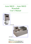
1
……………………………………………………………………………………………………
Troubleshooting
CryoSmart 1 - CryoSmart 20
……………………………………………………………………………………………………
ASTORI TECNICA di Astori Claudia & C. s.n.c. - Via Stelle, 11 - 25020 Poncarale (BS)
Phone no.: +39 030 2540240 - Fax no.: +39 030 2640812
E-mail: [email protected] - www.astorioscar.com
-
Italy
……………………………………………………………………………………………………
Troubleshooting
CryoSmart 1 - CryoSmart 20
……………………………………………………………………………………………………
ASTORI SERVICE DEPARTMENT…………………………………………………………………... 4
CHAPTER 1 – PROBLEMS AND SOLUTIONS…………………………………………………… 5
THE INSTRUMENT RETURNS “SAMPLE FAILED”…………………………………………….…. 5
THE INSTRUMENT RETURNS “TIME OUT”……………………………………………………….. 5
THE INSTRUMENT DOES NOT RUN THE ANALYSIS…………...…………………………….… 6
BAD REPEATABILITY OF THE INSTRUMENT…………………………………………………….. 6
THE INSTRUMENT UNDERVALUES THE SAMPLES…………………………………………….. 7
THE INSTRUMENT OVERVALUES THE SAMPLES….…………………………………………… 7
THE FUSES BLOW…………………………………………………………………………………….. 7
INSUFFICIENT TEMPERATURE OF THE BATH (WAIT…)………………………………………. 8
THE CAROUSEL DOES NOT ROTATE (CryoSmart 20)……………...….………………..……… 8
WITH THE SAMPLING TUBE LOADED, THE HEAD DOES NOT GO DOWN…………………. 8
THE HEAD DOES NOT MOVE…………….…………………………………………………………. 9
THE STIRRER DOES NOT WORK………………….……………………………………………….. 9
THE STIRRER BREAKS THE SAMPLING TUBES………………………………………………… 9
THE INSTRUMENT DOES NOT PRINT ANY DATA..……………………………………………. 10
CHAPTER 2 – ADJUSTMENTS…………………………………………………………………… 11
THERMISTOR ADJUSTMENT………………………………………………………………………. 11
2
STIRRER ADJUSTMENT……………………………………………………………………………. 12
AGITATION ADJUSTMENT…………………………………………………………………………. 13
FREEZING STROKE ADJUSTMENT………………………………………………………………. 14
CORRECT POSITION OF THE PHOTOCELL (CryoSmart 20)……….………...………………. 16
THERMISTOR REPLACEMENT……………………………………………………………………. 17
CHAPTER 3 – ANALYSIS AND CALIBRATION…………………………………………………... 18
ANALYSIS……………………………………………………………………………………………… 18
CALIBRATION………………………………………………………………………………………… 19
CHAPTER 4 – INSTRUMENT……………………………………………………………………….. 21
PARTS………………………………………………………………………………………………….. 21
BLOCK DIAGRAM…………………………………………………………………………….………. 23
FRONT PANEL…………………………………………………………………………….………….. 24
REAR PANEL………………………………………………………………………………………….. 25
BATH…………………………………………………………………………………………………… 26
SPRING………………………………………………………………………………………………… 27
HEAD…………………………………………………………………………………………………… 29
MANDREL……………………………………………………………………………………………… 30
MOTOR (CryoSmart 20)……......………………………………………………………..…………... 30
PUMP…………………………………………………………………………………………………… 31
FILTER…………………………………………………………………………………………………. 33
ACTUATOR……………………………………………………………………………………………. 33
BOARD…………………………………………………………………………………………………. 34
FAN……………………………………………………………………………………………………... 36
PRINTER COMMUNICATION……………………………………………………………………….. 36
FUSES……………………………………………………………………………………………….…. 37
FEATURES…………………………………………………………………………………………….. 37
3
ASTORI SERVICE DEPARTMENT
In case of any trouble, please contact our SERVICE DEPARTMENT at the telephone number:
+39 030 2540240, fax number +39 030 2640812 or by e-mail at: [email protected].
This manual was made to clarify the most frequent troubles and how to solve the problems
occurring to our cryoscopes, when our technical assistance is not necessary.
In this manual you will find lots of possible causes describing problems, evaluated by the
technical assistance.
Detailed descriptions are listed, problem by problem, along with clear explanations about how
to solve them.
However, please do not hesitate to call us in case of any problem you might find; moreover, we
would like to remind you that all our cryoscopes include a 12-month warranty period starting
from the purchase date.
Kind regards.
Astori Tecnica s.n.c.
4
CHAPTER 1 - PROBLEMS AND SOLUTIONS
THE INSTRUMENT RETURNS “SAMPLE FAILED”
Problem:
The result of the analysis is “SAMPLE FAILED”.
Causes:
1. The “freezing stroke” is not strong enough for milk samples.
2. Thermistor failure (or not connected).
Solutions:
1. Adjust the “freezing stroke” (see “Freezing Stroke Adjustment”).
2. Check the connections of the thermistor.
3. Replace the thermistor.
-- If you press
the head goes down and immediately the instrument makes the “freezing
stroke“: check the connections of the thermistor and/or replace it.
THE INSTRUMENT RETURNS “TIME OUT”
Problem:
The result of the analysis is ”TIME OUT”.
Causes:
1. The analyzed sample is too cold.
2. The milk is altered (high presence of salts, urea, etc.).
3. The temperature of the bath is too high or too low.
4. The agitation is too strong and air bubbles are created inside the sample; the sample is
freezed before – 3°C.
5. The volume of the cooling liquid is not enough.
6. The carousel did not rotate (CryoSmart 20).
7. The magnet is disconnected (see “Head”).
Solutions:
1. Check the temperature of the milk sample.
Too cold samples freeze before the “freezing stroke”.
2. Verifiy, using other methods, if the milk sample has been altered.
3. Check the temperature of the bath: -7°C ± 0.5°C.
4. Adjust the agitation (see “Agitation adjustment”).
5. The sample tubes must be clean: please, check for it. The pump must replace the liquid at
the end of every analysis, and the filter must be clean (see “Bath”, “Filter” and “Pump”)
6. Check the correct rotation of the carousel or the spring position (see “Spring”).
7. Check the magnet connections.
5
THE INSTRUMENT DOES NOT RUN THE ANALYSIS
Problem:
During an analysis, the temperature of the sample is the same one of the bath, but no error is
displayed.
Causes:
1. The lower microswitch is not correctly pressed.
Solutions:
1. Check the lower microswitch inside the actuator.
BAD REPEATABILITY OF THE INSTRUMENT
Problem:
The instrument does not show a good repeatability.
Causes:
1.
2.
3.
4.
5.
6.
Altered samples.
Bad adjustment of the agitation .
Bad adjustment of the ”freezing stroke”.
Wrong temperature of the bath.
Wrong position of the thermistor.
Broken thermistor or bad connections.
Solutions:
1. Check the integrity of the samples.
2. Adjust the agitation (see “Agitation Adjustment”).
3. Adjust the “freezing stroke” (see “Freezing Stroke Adjustment”).
4. Check the entire fluidic system. Check the tubes (they must be clean); check the pumping
system; check the liquid inside the tank (see “Rear Panel”), check the filter (replace it, if
necessary).
5. Check the position of the thermistor (see “Thermistor Adjustment”).
6. Check the fixing of the thermistor.
7. Check the connections or replace the thermistor.
6
THE INSTRUMENT UNDERVALUES THE SAMPLES
Problem:
The result of the analysis is undervalued.
Causes:
1. The sample is too cold.
2. The “freezing stroke” is too weak.
3. The thermistor is broken.
Solutions:
1. Check the milk temperature.
2. Adjust the “freezing stroke” (see “Freezing stroke adjustment”).
3. Replace the thermistor.
THE INSTRUMENT OVERVALUES THE SAMPLES
Problem:
The result of the analysis is overvalued.
Causes:
1. The thermistor is broken.
Solutions:
1. Replace the thermistor.
THE FUSES BLOW
Problem:
When you switch the instrument on, the fuses blow.
Causes:
1. Diodes bridge failure.
2. Power supply failure.
Solutions:
1. Check the diodes bridges.
2. Check the power supply system.
7
INSUFFICIENT TEMPERATURE OF THE BATH (WAIT…)
Problem:
The instrument does not keep the working temperature.
Causes:
1. Cooling bath failure.
2. Cooling bath control system failure.
Solution:
1. Check the cooling bath (Peltier cell).
2. Check the T2 (IRF540) MOSFET transistor.
THE CAROUSEL DOES NOT ROTATE (CryoSmart 20)
Problem:
When you press
the carousel does not rotate.
Causes:
1. Rotation system failure.
2. The microswitch is not correctly pressed.
Solutions:
1. Check the correct functionality of the rotation system (mechanical and electrical).
2. Check the correct functionality of the microswitches inside the actuator.
WITH THE SAMPLING TUBE LOADED, THE HEAD DOES NOT GO DOWN
Problem:
The tube is inside the duct but the head does not come down.
Causes:
1. Wrong position of the photocell.
2. Photocell failure.
Solutions:
1. Check the position of the photocell (see “correct position of the photocell”).
2. Replace the photocell.
8
THE HEAD DOES NOT MOVE
Problem:
The head does not move but the photocell is in a correct position.
Causes:
1. Microswitches failure.
2. Actuator failure.
Solutions:
1. Check the microswitches.
2. Check the actuator.
THE STIRRER DOES NOT WORK
Problem:
The stirrer does not work.
Causes:
1. Magnet failure.
Solutions:
1. Check the magnet connections.
THE STIRRER BREAKS THE SAMPLING TUBES
Problem:
The stirrer breaks the sampling tubes.
Causes:
1. The “freezing stroke” is too strong.
Solutions:
1. Adjust the “freezing stroke” (see “freezing stroke adjustment”)
9
THE INSTRUMENT DOES NOT PRINT ANY DATA
Problem:
The instrument does not print the results of the analyses or the parameters.
Causes:
1. Communication failure.
Solutions:
1. Check the connections of the printer (see “Printer communication”).
10
CHAPTER 2 - ADJUSTMENTS
THERMISTOR ADJUSTMENT
The correct position of the thermistor is showed here below. The glass ball of the thermistor
must be at the center of the semisphere and at 35,5 mm from the mandrel.
1
4
2
3
1.
2.
3.
4.
Mandrel
Tube
Thermistor
Stirrer
If the position is not correct, please follow this procedure:
1. Unscrew the screw with the hexagonal socket in its head that fixes the thermistor at the
mandrel.
2. Place the thermistor in the correct position.
3. Fix the thermistor at the mandrel.
4. Check the clamping of the thermistor.
11
MANDREL
HEX KEY
STIRRER ADJUSTMENT
The stirrer and the thermistor have to be at the same level (see “Thermistor adjustment”).
The stirrer must be centered like shown in the picture here below, and it must vibrate
symmetrically and freely inside the slot (see “mandrel” and see “head”).
1
2
4
3
1.
2.
3.
4.
Mandrel
Thermistor
Slot
Stirrer
12
AGITATION ADJUSTMENT
The agitation must avoid the production of air bubbles inside the tube. This adjustment
procedure can be made by using a calibration standard.
In perfect working conditions, the maximum stirrer amplitude is 2-3 mm when the stirrer itself is
properly placed inside the calibration standard.
To check the agitation strength, please follow this procedure:
1. Enter the main menu by pressing
2. Search for Agitation Test.
.
3. Press
.
4. Fill a tube with a calibration standard up to the level (volume) normally used with a sample
during a common analysis.
5. Place the tube under the mandrel (as a normal analysis should be performed).
6. Press
to start the test, press
to finish the test.
-- If the agitation looks too strong or too weak, follow these steps:
1. Enter the main menu by pressing
2. Search for Agitation Amplitude.
.
3. Increase or decrease the value by pressing
.
CORRECT
13
WRONG
FREEZING STROKE ADJUSTMENT
The correct “freezing stroke” must: hit the walls of the tube, stir all the liquid, avoid the
breakage of the tubes.
To adjust the freezing stroke, please follow this procedure:
1. Enter the main menu by pressing
2. Search for Stirrer Test.
3. Press
.
4. Fill a tube with a calibration standard up to the level (volume) normally used with a sample
during a common analysis.
5. Place the tube under the mandrel (as a normal analysis should be performed).
6. Press
to start the test, press
to finish the test.
7. Run a lot of tests to check if the undesired possibility to break a tube exists.
-- If during a test the stirrer breaks a tube, proceed like described here below:
1. Enter the main menu by pressing
2. Search for Stirrer Test.
3. Press
4.
5.
6.
7.
.
.
to start the test.
Press
Unlock the adjustment trimmer (see “Rear panel”).
Decrease the value by turning it anticlockwise.
Lock the trimmer again.
14
.
8. Press
9. Run some new tests to check for the undesired possibility to break a tube.
-- If the freezing stroke is too weak, follow the steps here below:
1. Enter the main menu by pressing
2. Search for Stirrer Test.
3. Press
4.
5.
6.
7.
.
.
to start the test.
Press
Unlock the adjustment trimmer (see “Rear panel”).
Increase the value by turning it clockwise.
Lock the trimmer again.
.
8. Press
9. Run some new tests to check for the undesired possibility to break a tube.
LOCKING
SYSTEM
TRIMMER
15
CORRECT POSITION OF THE PHOTOCELL (CryoSmart 20)
The correct position of the photocell is described in the next pictures.
The photocell must point over the semisphere.
16
THERMISTOR REPLACEMENT
To replace a thermistor, please follow the procedure as described here below:
1. Disconnect the instrument from the main supply.
2. Open the head.
3. Unscrew the screw (the one with the hexagonal socket in its head) that fixes the thermistor at
the mandrel (see “Thermistor Adjustment“)
4. Get the soldered cables free from their insulation coats (see “Head“).
5. Unsolder the thermistor cables.
6. Extract the thermistor from the mandrel by pulling it down.
7. Insert the new thermistor from the bottom of the mandrel. Please, pay attention! Do not hit
the thermistor glass ball.
8. Solder the cables of the new thermistor. Check that the new solders are done correctly.
9. Insulate the solders.
10. Check the thermistor position (see “Thermistor Adjustment”).
11. Fix the thermistor.
12. Fix the cables of the thermistor; be careful not to tend them and not to place them too close
to the stirrer and/or the magnet. (see “Head”)
13. Close the head.
14. Proceed with a new calibration procedure (see “Calibration”).
17
CHAPTER 3 - ANALYSIS AND CALIBRATION
ANALYSIS
The correct analysis of the cryoscopic point should respect the following curve:
1
2
4
3
1.
2.
3.
4.
Start analysis
Agitation
Freezing stroke
Plateau
18
CALIBRATION
Before running each calibration procedure, check the condition of the calibration standards.
Gently turn the bottle upside down and rotate it several times to mix its content thoroughly. The
standard solutions should not be used if the bottle is filled for less than one quarter in
comparison to its total capacity.
The shelf life of the standards covers 12 months from the date of production.
To perform a correct calibration procedure, please follow the instructions here below:
1. Enter the main menu by pressing the
2. Search for Calibration Reset.
3. Press the
button.
button.
again to confirm.
4. Press
5. Clean the mandrel, the thermistor and stirrer with a piece of soft paper.
6. Prepare 1 sample of the - 0.408°C calibration standard.
7. Start the analysis by pressing
.
8. Wait until the end of the analysis and press the
9. Press
button.
.
to confirm the calibration.
10. Press
11. Clean the mandrel, the thermistor and the stirrer with a piece of soft paper.
12. Prepare 1 sample of the - 0.600°C calibration standard.
13. Start a new analysis by pressing
.
14. Wait until the end of the analysis, then press the
15. Press
.
16. Press
.
17. Press
button.
again to confirm.
Now, a new calibration procedure is necessary.
Repeat the operations from step 5 to 17 using 3 replicates for each calibration standard.
Check the repeatability of the values: if the repeatability is bad, check the thermistor for any
breakage; maybe, it requires a replacement.
After finishing the calibration procedure, run a new analysis with 5 replicates of the - 0.512°C
calibration standard.
19
-- If the repeatability of the 5 replicates looks good but the value is different from - 0.512°C,
follow this procedure:
1. Enter the main menu by pressing
2. Select To Linearize.
.
3. Increase or decrease the value if the results are overvalued or undervalued using the
buttons. Any variation of ± 5 on “Linear” means ± 0.001°C.
Example:
VALUE READED
-0.513°C
-0.510°C
LINEARITY
-15
+10
MODIFY
+5
-10
NEW VALUE
-10
0
4. Switch the instrument off and on if you change the linearity value.
20
CHAPTER 4 - INSTRUMENT
PARTS
-- CryoSmart 1
5
1
6
2
7
3
4
8
1.
2.
3.
4.
5.
6.
7.
8.
Mandrel
Thermistor and Stirrer
Duct
Front panel
Head
Actuator
Rear Panel
Grate
21
-- CryoSmart 20
1
2
3
7
4
5
8
6
1.
2.
3.
4.
5.
6.
7.
8.
Head
Mandrel
Actuator
Carousel
Rear Panel
Grate
Thermistor and Stirrer
Front Panel
22
BLOCK DIAGRAM
STEP
MOTOR
(CryoSmart 20)
ACTUATOR
DISPLAY
PELTIER
CELL
PROGRAM
MEMORY
PERISTALTIC
PUMP
CPU
STIRRER
FLASH
MEMORY
RS232
PHOTOCELL
(CryoSmart 20)
NTC
PT100
MICRO
SWITCHES
BUTTONS
POWER
SUPPLY
FAN
23
FRONT PANEL
1
2
5
3
6
4
1.
2.
3.
4.
5.
6.
Display
MENU
CAL / ESC
DOWN / ▼
START-STOP / OK
UP / ▲
The keys have two different colours: the white side runs the operational functions of the
instrument; the orange side allows the visualization and modification of the functions after
entering the “MENU”.
The
button allows to enter and to scroll through the functions. It allows to scroll through
the calibration menu.
The START-STOP / OK key
is used to start or stop the analysis. Pay attention: put the
sample first and then press START.
When the START key is pressed and the analysis has started, the display shows the sample
temperature, the reference value to calculate the added water percentage and, after the
freezing stroke has done, the added water percentage of the sample.
The START-STOP key is also used to give confirmations (OK) and it allows to enter and
confirm the functions of the menu.
The CAL/ESC key
(when used as ESC) allows to exit the functions of the menu. When
used as CAL, it allows the calibration of the instrument.
The keys
are used to manually lower and raise the head, by pressing and
releasing the proper key.
24
REAR PANEL
1
2
7
3
8
4
5
9
10
6
11
1. Automatic refilling tube
2. Filter
3. Trimmer
4. Data input (Program)
5. Printer
6. Cooling liquid tank
7. Waste
8. Main switch
9. Fuses compartment
10. Supply connector
11. Peristaltic pump
25
BATH
The bath is cooled by means of a Peltier cell (+15 V AC) at –7°C ± 0.5°C .
1
2
3
1. Duct
2. Cooling bath body
3. Cooling system
The replacement of the liquid inside the bath is possible by: the external bottle, the peristaltic
pump and the waste tube.
When the instrument is turned on, the refilling of the bath is performed automatically.
At the end of every analysis, the cooling liquid is completely replaced thanks to the circuit, just
described.
26
PUMP
COOLING BATH
FILTER
WASTE
DUCT
BOTTLE
The temperature control in the bath is realized like in the figure below.
The PT100 probe sends data to the electronic control board, directly. A PID controller pilots the
MOSFET transistor IRF540.
The fan system gets the heat (produced by the Peltier cell) out of the equipment. (see “Fan”).
27
SPRING
Inside the cooling bath there is a spring for the sample tube.
Pay attention! The spring must be positioned in the duct exactly as described in the picture
below.
-- CryoSmart 1:
UP
-- CryoSmart 20:
The spring must be at the same level of the bath's duct.
-- If the spring is positioned higher than the duct, probably will be dragged by the tubes.
-- If the spring is too low, probably will prevent the carousel rotation.
SMALL
DIAMETER
UP
BIG
DIAMETER
28
HEAD
Inside the head there are the following components: the magnet, the lamina who allows the
stirrer swing, and the connections of the thermistor.
6
1
7
2
8
3
4
7
5
9
1.
2.
3.
4.
5.
6.
7.
8.
9.
Lamina
Magnet
Stirrer support
Thermistor cables
Head
Centering nut
Magnet clamper
Stirrer cables
Mandrel
To center the stirrer, please follow this procedure:
1. Unscrew the nuts and move the lamina until the stirrer is in the correct position. (see “Stirrer
Adjustment”).
2. Screw the nuts again.
One method to adjust the “Freezing Stroke” and the agitation is by moving the magnet:
Unscrew the screw (the one with the hexagonal socket in its head) that clamps the magnet, in
order to approach and move away the magnet from the stirrer support.
1. By moving the magnet closer, the “freezing stoke” becomes gentler and its working quality
improves, but the agitation becomes too strong.
2. By moving the magnet away, the agitation works better, but the “freezing stroke” increases
its power and a breakage of the sample tubes becomes possible.
Find the better position where both agitation and “freezing stroke” work correctly.
Then clamp the magnet again.
After finishing these operations, adjust the agitation and the freezing stroke.
(see “Agitation Adjustment” and “Freezing Stroke Adjustment”).
29
MANDREL
The thermistor and the stirrer are located inside the mandrel.
MOTOR (CryoSmart 20)
The step motor moves the carousel.
30
PUMP
The pump is the element that allows the refilling of the liquid inside the cooling bath.
CLIP B
CLIP A
CLIP A
CLIP B
If the pump is dirty, an insufficient volume of liquid may be replaced inside the bath.
To clean and replace the tube, please follow this procedure:
1. Release the pump by pressing the A clips.
31
2. Open the pump by pressing the B clips.
3. Replace the tube.
32
FILTER
If the filter is dirty, the cooling liquid cannot fill the cooling bath properly, so that the results may
be inaccurate.
Replace the filter when decribed.
Pay attention! Place the filter in the right position. The arrow (on the filter body) must be
addressed upfront.
UP
ACTUATOR
The actuator is the component that moves the head up and down.
The microswitches are located inside the actuator.
33
BOARD
The board allows all the following operations:
1. Move the head.
2. Rotate the carousel.
3. Read data from the photocell.
4. Control the cooling bath.
5. Pilot the stirrer.
6. Read data from the thermistor.
7. Communicate with the printer .
8. HMI (Human Machine Interface).
1
8
J2
9
61
11
12
15
16 17
18
60
21
22
59
58
25
57
56
26
29
55
IRF540
50
49
46
45 44
# PIN
1
2
3
4
5
6
7
8
9
10
11
PIN Name
Photocell A
Photocell B
Photocell +12 V
Photocell GND
NC
Microswitch Common
Microswitch Up
Microswitch Down
NC
NC
NC
43 42
41
39
38
Type
IN
IN
OUT
OUT
IN
IN
IN
-
37
34
33
30
# Connection
3
4
5
6
7
8
9
34
12
13
14
15
16
17
18
19
20
21
22
23
24
25
26
27
28
29
30
31
32
33
34
35
36
37
38
39
40
41
42
43
44
45
46
47
48
49
50
51
52
53
54
55
56
57
58
59
60
61
Step Motor
Step Motor
Step Motor
Step Motor
9 V ~ AC (step motor)
9 V ~ AC (step motor)
NC
NC
NC
NC
+ Actuator
- Actuator
12 V ~ AC (actuator)
12 V ~ AC (actuator)
9 V ~ AC (pump)
9 V ~ AC (pump)
+ Pump
- Pump
GND
Peltier Control
NC
+12 V Peltier
Relè Stirrer
Relè Stirrer
NC
NC
NC
0 V transformer (stirrer)
GND stirrer
Relè Stirrer
15V ~ AC (agitation)
15V ~ AC (agitation)
NC
NC
NC
NC
NC
NC
Thermistor
Thermistor
Thermistor Shield
Pt100
Pt100
Pt100
8 V ~ AC (CPU)
8 V ~ AC (CPU)
NC
NC
12 V ~ AC (sensors)
12 V ~ AC (sensors)
IN
IN
IN
IN
IN
IN
OUT
OUT
IN
IN
IN
IN
OUT
OUT
IN
OUT
IN
OUT
OUT
IN
IN
IN
IN
IN
IN
IN
OUT
IN
IN
IN
IN
IN
IN
IN
10
11
12
13
14
15
16
17
18
19
14
15
20
21
22
23
24
25
26
27
28
29
30
31
32
33
34
35
35
36
37
38
18
19
35
FAN
The fan system takes the heat produced by the peltier cell out of the unit.
PRINTER COMMUNICATION
The communication from the board up to the printer is realized with a RS232 communication
interface.
36
FUSES
The instrument has 2 fuses of 6,3 A each.
To replace the fuses, please follow this procedure:
1. Disconnect the cryoscope from the main supply.
2. Open the fuse compartment.
3. Replace the fuses.
1
2
3
1. Main switch
2. Fuse compartment.
3. Supply connector.
FEATURES
-- Mechanical features:
Dimensions: 255 x 360 x 370 mm
Weight: 18,5 Kg
-- Electrical features:
Power supply: 230 V – 50 Hz
Electrical consumption: 150 W
Overload fuses: 2 x 6,3 A
Main supply voltage maximum fluctuations: ± 10% of the nominal voltage
Transient overvoltages: II
Board: CryoSmart2
Software: 1.5
-- Operating features:
Maximum altitude: 2000 m
Maximum relative humidity: 80% for temperatures up to 31°C decreasing linearly to 50%
relative humidity at 40°C.
Operating temperature: from +5°C to +40°C.
Storage temperature: from –10°C to +50°C.
37