1
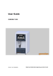
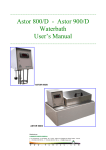
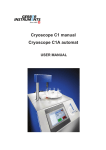
……………………………………………………………………………………………………...
User’s Manual
“CryoStyle 40”
Cryoscope
……………………………………………………………………………………………………...
ASTORI TECNICA di Fagotti Giovanni & C. s.n.c. - Via Stelle, 11 - 25020 Poncarale (BS) - ITALY
Phone: +39 030 2540240 - Fax: +39 030 2640812
E-mail: [email protected] - www.astorilab.com
……………………………………………………………………………………………………...
User’s Manual
“CryoStyle 40”
Cryoscope
……………………………………………………………………………………………………...
WARNINGS ………………………………………………………………………………….....………. 5
FEATURES ………………..............…………………………………………………………………... 5
MECHANICAL FEATURES ………………...............……………………………………….. 5
ELECTRICAL FEATURES …………………………...............……………………………… 5
CLIMATIC FEATURES, STORAGE, PACKAGING AND USE …………….............……. 5
SAFETY DEVICES ………………………….…………………………………………………………. 6
EMERGENCY PUSHBUTTON ……………………………….....……..……………………. 6
INSTALLATION ………………………..………………………………………………………………. 6
SET UP ………………………........................……………………………………………….. 6
FUNCTIONING …………...................………………........................................……….....………. 7
TOUCH SCREEN ……………………………………………………………………………... 7
“DEVICE READY MASK” …………………………………………………………………….. 8
PASSWORD …………………………………………………………………………………… 8
CALIBRATION AND ANALYSIS ………………………………………….………………………….. 9
PREPARATION OF SAMPLES ……………....……………………………………………... 9
ANALYSIS …...……………………………………………………………………………….. 9
CALIBRATION TECHNIQUE …………………………………………………………..…… 11
CALIBRATION ..……………………………………………………………………………… 11
REFERENCE FOR ADDED WATER CALCULATION …………………..............……………… 12
REFERENCE SELECTION ……………..........……………………………………………. 12
MODIFYING THE REFERENCE …………………………………………………………… 13
ALARMS ………………………………………………………………………………………………. 13
2
ALARMS CANCELLATION ...........…………………………………………………………. 13
HOW TO CANCEL THE “SUBST. COOLING LIQUID” ALARM ................................... 14
ADJUSTMENTS ………………………………….....……….……………………………………….. 15
MENU .......................... ……………………………………………………………………………… 15
MAIN MENU ……………….............………………………………………………………… 15
PARAMETERS MENU ………………………………………………………………………. 16
CONFIRMATION MENU ………….....……………………………………………………… 17
MEASUREMENTS MENU ……………………………………………….…………………. 17
BATH MENU ………………………...……………………………………………………….. 18
MOTORS MENU ……..……………………………………………………………………… 18
MANUFACTURER MENU ………………………………………………………………….. 19
MEASUREMENTS MEMORY ………………………………………...……………………. 20
ALARMS MENU ……………………………………………………………………………... 21
STIRRER TEST MENU ……………..........………………………………………………... 22
DISPLAY MENU …………….............………………………………………………………. 23
LANGUAGE MENU …………….....………………………………………………………… 23
Pt100 MENU ................................................................................................................. 24
ANALYSIS MENU ......................................................................................................... 24
SENSORS TABLE ........................................................................................................ 25
PID MENU ..................................................................................................................... 26
TEMP MENU ................................................................................................................. 27
DEBUG ......................................................................................................................... 27
PID TUNING MENU ...................................................................................................... 28
DOWNLOAD MENU ..................................................................................................... 28
KEYBOARD .................................................................................................................. 29
DOWNLOAD MEASUREMENTS …………………..………………………………………………. 30
HOW TO ESTABLISH A CONNECTION ………………………………………..………… 30
TRANSFER MEASUREMENTS ……......………………………………………………….. 34
SAVE MEASUREMENTS …………………………………..…… ………………………… 35
ORDINARY MAINTENANCE ……………….……………………………………………………… 35
CASE CLEANING ………….........………………………………………………………….. 35
FILTER CLEANING ……………...………………………………………………………….. 35
3
DAILY MAINTENANCE ………………………......................................…………………. 35
EXTRAORDINARY MAINTENANCE …………….………………………………………... 35
CHECK AND SUBSTITUTION OF THE COOLING LIQUID ………………….....……… 36
CHECK AND SUBSTITUTION OF THE FILTER ………………...………………………. 36
HOW TO MOVE AND SHIP THE CRYOSCOPE ……...............………………………………… 36
MOVING THE CRYOSCOPE …………….................…………………………………….. 36
SHIPPING THE CRYOSCOPE ……………….........……………………………………… 36
PRINCIPAL COMPONENTS ………...……………………………………………………………… 37
COOLING BATH ………………………………...........................…………………………. 37
HEAD ….....…………………………………………………………………………………… 37
MEASUREMENT THERMISTOR …………………………...……………………………... 38
STIRRER ……………………………………………………………………………………… 38
SPRING …………………………………………………………..............................……… 38
REAR PANEL ……………………………….........................................................……… 39
PRINTER ……………………......……………………………………………………………. 39
PRODUCTS SUPPLIED WITH THE CRYOSCOPE………………………………………………. 40
ACCESSORIES AND CONSUMABLES ...........…………………………………………………... 40
DOCUMENT VALIDITY ……...........………………………………………………………………... 40
WARRANTY ………………….………………………………………………………………………. 40
DISPOSAL …………………………………………………………………………........……………. 41
MENU TABLE ……………………………………………………………………………………....… 42
FUNCTION TABLE ………………………………………………………………………………...… 43
COOLING BATH FORM …………………………………….......................................…………... 45
DECLARATION OF CE CONFORMITY ................................................................................... 46
4
WARNINGS
Before using the equipment read this user guide
This manual is an integral part of the product and must be conserved for future
consultation.
In it you can find important information regarding safety of use and maintenance.
Read carefully the instructions contained in this manual.
This equipment has been realized for the analysis of milk samples or derivatives, for
calibration standard solutions and check solutions for cryoscopy.
Even if this device is provided with protections, the use of the equipment without
following the described procedures could produce a wrong working and damages on the
equipment.
The manufacturer is not liable for damages to people or things caused by improper use
of the equipment and/or not respect of the laws, regulations and instructions described
below.
FEATURES
MECHANICAL FEATURES
- Dimensions: 330 x 375 x 527 mm
- Weight: 26,8 Kg
ELECTRICAL FEATURES
- Electrical supply: 115 V ~ 60 Hz
230 V ~ 50 Hz
- Max. variation of the tension: ±10% of the nominal tension
- Transitory overload: II
- Absorption: 250 W
- Safety fuses: 2 x 2 A, 250 V
CLIMATIC FEATURES, STORAGE, PACKAGING AND USE
- Maximum working temperatures: from 5° to 36°C
- Relative humidity: max. 80% for temperatures up to 31°C, with a linear decrease up to 50% at
a temperature of 36°C.
- Pollution degree: 2
- IP protection grade: 20
5
SAFETY DEVICES
EMERGENCY PUSHBUTTON
The equipment is provided with an emergency pushbutton which interrupts the electrical supply
when a dangerous situation is occurring.
In order to deactivate the safety device turn the pushbutton in the direction of the arrows as
showed in the picture.
INSTALLATION
Avoid placing the equipment near heating sources or windows hit by sunlight.
Place the equipment far from the wall: in this way it would be easier to operate both on the
main switch and on the socket.
The equipment works with 230 V ~ ±10% and a frequency of 50Hz or with 115 V ~ ±10% and a
frequency of 60 Hz.
The electrical socket must supply 3 Ampère continuously.
Check the tension selector located under the equipment: it must be positioned on the
value of the available tension.
According to the electrical safety regulations, check that a good earth connection is
provided. The manufacturer is not liable in case of damage due to a lack of compliance
of this normative.
SET UP
1. Remove the cryoscope from its package: in order to perform this operation correctly, always
hold the equipment by its sides and its lower part with the help of another person.
2. Place it on a perfectly horizontal bench in order to avoid vibrations or movements.
3. Check the tension selector located at the bottom: it must be in the correct position.
The arrow positioned on the selector has to indicate the local tension available. Whether the
position is wrong, rotate the selector by means of a proper screwdriver.
4. Connect the cable to the main socket positioned on the rear of the equipment.
5. Insert the plug in the electrical socket.
6
6. Turn the cryoscope on by pressing the main switch positioned on the back.
7. If the equipment does not turn on, verify that the emergency pushbutton is not pressed. In
this case deactivate it by turning in the direction indicated on the head.
8. Turn the equipment on again.
9. If the equipment does not turn on, check the integrity of the fuses and replace them if
necessary.
10. Turn the equipment on.
11. Wait until the head has completely lifted up and draw the tube.
Pay attention not to hit the reading thermistor.
12. Turn the equipment off.
13. Fill the vessel positioned on the back of the equipment with cooling liquid until the maximum
level indicated. Check that the little pipe collects from the very bottom of the vessel.
14. Turn the equipment on again: the cooling bath will be filled automatically.
15. Wait until the bath reaches the correct working temperature (the display will show the
message EQUIPMENT READY). We suggest to wait at least 10 minutes before proceeding
with the analysis: in this way the equipment could stabilize.
16. Verify that the cryoscope is correctly calibrated by performing 3 analyses of 3 replicates of
standard 0,512°C. In order to perform this operation correctly, fill the tubes with the 0,512°C
check standard until the level of 2,5 ml.
. Repeat this operation for each sample.
Position the tube inside the duct, then press
If the result differs for more than ± 0.002°C in relation to the nominal value of the standard,
proceed with the calibration according to the instructions below.
FUNCTIONING
TOUCH SCREEN
The equipment includes the “Touch Screen” system.
Press the buttons that appear on the display to enter the functions and menus.
7
“DEVICE READY” MASK
When “DEVICE READY” appears on the display the measurements or the calibration can start.
The display will show:
1
2
3
4
5
11
6
10
7
9
8
1. Date: date, format DD/MM/YY;
2. Time: time, format HH:MM;
3. Bath Temp: temperature of the cooling bath;
4. PSW: it enters the password menu;
5. Type: it enters the milk reference value;
6. Cal.: it enters the calibration menu;
7. Menu: it returns to the main menu;
8. Start: it starts the analysis;
9. <R>: it rotates the carousel;
10. ↑: it lifts the head;
11. ↓: it lowers the head.
PASSWORD
The equipment includes a password to block the setting functions to unauthorized operators.
Without password, only a few functions are accessible.
The password default value is <0>; at the moment of installation all the functions are accessible
without password.
The password value can be changed anytime by the person in charge in the laboratory by
pressing “Password” and inserting the current value; then enter the function “New Password”
and digit the new value.
The calibration procedure is not covered by any identification code (password).
8
1
2
3
1. Password: it enters the current password value.
2. New Password: it enters the new password value.
3. Esc: it returns to the “Device Ready” mask.
CALIBRATION AND ANALYSIS
PREPARATION OF SAMPLES
Milk:
1. Analyze only fresh milk samples without preservatives.
2. The samples temperature must be between 15°C and 30°C.
3. Do not analyze cool milk samples.
4. Turn the vessel upside down several times avoiding the formation of bubbles.
Creams:
1. Analyze only fresh cream samples.
2. Before proceeding the analysis, heat the cream sample up to 30°C, let it cool down until it
reaches the room temperature and mix it constantly.
ANALYSIS
1. Before performing the analysis, clean the stirrer and the thermistor by using a soft piece of
paper.
2. Be sure that the tubes are completely dry and clean. Do not use tubes not recommended by
the manufacturer.
3. Be sure that the display indicates the message: “EQUIPMENT READY”.
4. Fill the tubes with 2,5 ml of samples.
5. Place the tubes in the holes of the carousel and press
.
9
Then the display will show the following curve:
1
2
5
3
6
4
1. Sample number;
2. Analysis curve;
3. STOP: it interrupts the analysis;
4. Kind of milk;
5. Rif.: water reference value;
6. Menu: it returns to the main menu.
When a sample analysis finishes, the display will show:
5
6
1
2
7
3
8
4
10
1. Ref.: water reference value;
2. Analysis result (in mC or mH);
3. STOP: it stops the analysis;
4. Reset: it cancels the alarm (if an alarm is on);
5. Date: date;
6. Time: time;
7. Percentage of added water;
8. Menu: it enters the main menu.
CALIBRATION TECHNIQUE
1. Before using a standard solution, gently turn its bottle upside down and rotate it several
times to mix its content thoroughly. Pay attention not to shake it and avoid the formation of
bubbles. The standard solutions should not be used from bottles that are less than one quarter
full. Gently wipe the thermistor and the stirrer downwards only by using a soft piece of paper.
2 Calibration procedure: it is warmly suggested to average the readings of 3 replicates of each
standard. The accuracy should be better than ± 0.002°C. Any first reading may be incorrect, for
this reason do not consider the first value.
3. A re-calibration should be carried out in the following cases: when there is a high variability
among the samples analyzed; anytime the thermistor is replaced or if any mistake could be
occurred during the calibration procedure.
4. When the calibration procedure has been correctly achieved, it is possible to check the
accuracy of the curve by measuring the control solution (-0,512°C ± 0,002°C) or both the
calibration standard solutions.
CALIBRATION
Analyze at least 3 replicates of the -0,408°C standard. Check the repeatability (± 0,002°C) of
the results as they are displayed. If the repeatability looks correct, press
calibrate these measured values.
The display will show:
in order to
1
4
2
3
5
11
1. Cal. A –0.408: it confirms the calibration (–0.408°C);
2. Cal. A –0.600: it confirms the calibration (–0.600°C);
3. Reset A: it resets the calibration;
4. Actual digital values;
5. Esc: it returns to the “Device Ready” mask.
Confirm the calibration by pressing the key associated to the reference value.
The equipment memorizes the last read value.
Proceed with the same operation with the standard -0.600°C.
REFERENCE FOR ADDED WATER CALCULATION
REFERENCE SELECTION
Before processing the measurement it is possible to select the kind of milk. In this way the
added water reference value will be modified according to the milk you need to analyze.
In order to select the milk, press the
button.
1
2
3
4
5
6
7
1. Cow: cow milk;
2. Sheep: sheep milk;
3. Goat: goat milk;
4. Buffalo: buffalo milk;
5. Other: other kind of milk;
6. Esc: it returns to the “Device Ready” mask;
7. Modify: it modifies the water reference value.
Note that the selected type of milk is marked in bold.
12
MODIFYING THE REFERENCE
1
3
2
1. Types of milk;
2. Esc: it returns to the previous menu;
3. Current values.
ALARMS
In case an alarm situation occurs, the message “ALARM” appears on the top of the display
along with a message indicating the operation necessary to cancel this message. The word KO
will appear in bold in correspondence to the active alarm.
The alarms are always accompanied also by an acoustic signal.
ALARMS CANCELLATION
The alarm signals can be erased by pressing the reset button located in the panel showing the
analysis results or inside the alarm menu.
1
2
3
13
1. Alarm condition;
2. Alarm message (in negative);
3. Reset: It allows to cancel alarm.
HOW TO CANCEL THE “SUBST. COOLING LIQUID” ALARM
It is quite different to cancel the “Subst. Cooling Liquid” alarm: in fact it is necessary to set it
again. Please proceed as described in the following paragraph.
Replace the cooling liquid contained in the plastic bottle located behind the equipment.
Follow the path displayed on the screen: menu bath press the “cooling liquid” button
which will turn negative.
Turn the cryoscope off and on again.
During the substitution of the cooling liquid clean the filter, or replace it if necessary.
14
ADJUSTMENTS
It is possible to make an amplitude regulation of the stirrer (freezing stroke) by turning the
trimmer behind the equipment.
To unlock the trimmer, please rotate the locking system anticlockwise.
Increase or decrease the stirrer strength by rotating in a clockwise or anticlockwise direction.
When the stirring power is properly adjusted, lock the trimmer again.
1
2
1. Locking system
2. Trimmer
MENU
MAIN MENU
1
5
2
6
3
7
4
8
1. Parameter: it enters the parameter menu;
2. Bath: it shows the cooling bath menu;
3. Manufact.: menu reserved to the Service Dept.;
4. Alarms: it enters the alarms menu;
5. Measures: It includes sensors data and parameters;
6. Motors: it shows the motor menu;
7. Memory: it enters the measurements memory;
8. Esc :it returns to the “Device Ready” mask;
15
PARAMETERS MENU
This menu is composed by two pages:
6
1
2
3
7
4
5
8
9
6
10
11
12
13
1. S. Tubes N.: it modifies the size of the analysis batch (Maximum 40);
2. Stirrer Test: it enters the “Stirrer Test” menu;
3. Pump Test: it refills the cooling bath and checks the pump;
4. Prn Param: it prints some technical parameters;
5. Esc: it returns to the main menu;
6. Actual values;
7. Test Up/Dw: this function is reserved to the Service Dept.;
8. Next: it scrolls to the next page;
9. Scale: it modifies the measurement unit: <0> -°C
<1> - °H;
10. Language: it modifies the language;
11. Display: it shows the display menu;
12. Default Par.: it erases all settings;
N.B.: Do not modify this parameter.
(The modification of this parameter may erase ALL the setting data related to the
equipment);
13. Esc: it returns to the previous page.
16
CONFIRMATION MENU
To avoid to perform unwilling modifications to the equipment settings, some functions ask for a
further confirmation.
1
2
3
1. OK: it confirms the previous operation;
2. Cancel: it cancels the previous operation;
3. Esc: it returns to the previous menu;
MEASUREMENT MENU
1
2
3
4
1. Pt100: it includes the parameters of the bath probe;
2. Analysis: it includes the reading thermistor parameters;
3. Sensors: it shows sensors data and the parameters related to the A/D converters;
4. Esc: it returns to the previous menu.
17
BATH MENU
1
2
3
4
1. PID: it modifies the control parameters of the cooling bath;
2. Temp.: it modifies the temperature of the cooling bath;
3. Cooling L.: it removes the alarm related to the substitution of the cooling liquid;
4. Esc: it returns to the main menu.
MOTORS MENU
This menu is composed by two pages:
1
2
5
3
4
6
18
7
8
9
5
10
11
12
13
1. Duration T. s: pump activation time between two analyses;
2.Duration Man. s: start-up pump activation time;
3. Start Flag: pump automatic activation;
4. Esc: it returns to the main menu;
5. Actual values;
6. Next: it scrolls to the next page;
7. Tubes N max.: max tubes number available on the carousel;
8. Micro Step: it indicates the time between two microsteps;
9. Step Delay: it indicates the time needed to reach a tube before analysis;
10. Low Power: it indicates the minimum voltage applied to the carousel while maintaining its
position;
11. High Power: it indicates the minimum voltage applied to the carousel while rotating;
12. Pag. Prec.: it returns to the previous page;
13. Test Step: it rotates the carousel, press this button once more in order to interrupt the
rotation.
MANUFACTURER MENU
1
2
3
4
5
19
1. Update: it updates the cryoscope software;
2. Serial N.: it indicates the serial number of the cryoscope;
3. Prn Config: it prints the cryoscope configuration;
4. Debug: it shows the actual functioning and the situation of some relevant fields;
5. Esc: it returns to the main menu.
MEASUREMENTS MEMORY
1
2
5
3
4
1. Measurement raw
2. Data: by entering this parameter it is possible to download the data on a computer or erase
the measurements archive (see Download menu);
3. Next: it scrolls to the next page of measuring memory;
4. Prev: it scrolls to the previous page of measuring memory;
5. Esc: it returns to the main menu.
Every measurement is stored in memory according to the following scheme:
N. of sample
Date - Time
Analysis Result
% H2O
20
ALARMS MENU
1
2
3
4
1. Alarms list:
- Temp. Bath: insufficient temperature inside the bath;
- Tube: tube not detected after analysis;
- Database Full: database full;
- Cooling Liq:: replace the cooling liquid (see “Alarm” paragraph Alarms Cancellation);
- CRC Memory: wrong values in memory;
- A/D Error: error in the analogical / digital system conversion;
- Memory Flash: error during data writing;
- Head Motor: motor problem.
2. Warnings List:
- Time Out: the analysis runs out of time;
- Data Flash: memory warning.
3. Esc: it returns to the main menu;
4. Reset: it cancels the alarms.
21
STIRRER TEST MENU
This menu is composed by two pages:
1
4
2
4
5
3
6
7
8
5
9
10
11
1. Agitation: it adjusts the agitation force;
2. Stirrer: it adjusts the stirrer force;
3. Esc: it returns to the previous menu;
4. Test: it makes tests on the agitation and freezing stroke;
5. Present values;
6. Next: it scrolls to the next page;
7. Frequency: frequency of the wave shape on the stirrer;
8. # Sin.: number of approximation steps of the wave shape;
9. Type Wave: kind of wave on the stirrer;
10. Wave Off: number of not executed approximation steps;
11. Prev: it returns to the previous page.
22
DISPLAY MENU
1
2
6
3
4
5
1. Contrasts: it shows the contrast of the display;
2. Date: it shows the date in the DD/MM/YY format;
3. Hour: it shows the time in the HH:MM format;
4. Prn T Bridge: it prints the temperature on the checking bridge of the cooling bath;
5. Esc: it returns to the previous menu;
6. Present values.
LANGUAGE MENU
1
2
3
4
1. Italian
2. English
3. French
4. Esc: it returns to the previous menu.
The marked language value has to be considered as the selected one from the operator.
After modifying the language, it is necessary to turn the equipment off and on in order to make
the modification valid.
23
Pt100 MENU
1
5
2
5
6
3
4
1. Temp. –10 C: it shows the pt100 probe calibration values;
2. Temp. +10 C: it shows the pt100 probe calibration values;
3. Offset: pt100 probe temperature offset;
4. Esc: it returns to the previous menu;
5. Get: it acquires the value;
6. Actual values.
ANALYSIS MENU
1
2
6
3
4
5
1. Linearity: it shows the linearity of the reading channel;
2. Duration: it shows the reading time (duration of the plateau);
3. Dig. Filter: filter applied to the read value;
4. Floating Mean: number of data which can be filtered;
5. Esc: it returns to the previous menu;
6. Present values.
24
SENSORS TABLE
1
6
2
7
3
8
4
9
5
1. n A: read value from A/D converters on channel A;
2. n B: read value from A/D converters on channel B (disabled function on CryoStyle 40);
3. n Bath: read value from pt100 sensor;
4. UP DW: values of microswitches;
5. Esc: it returns to the previous menu;
6. T: nA value converted in temperature;
7. T: nB value converted in temperature;
8. T Bath: present temperature of the cooling bath;
9. FCA FCB: photoelectric cells condition.
25
PID MENU
This menu is composed by two pages:
1
2
3
7
4
5
6
8
9
10
7
11
12
13
1. Cycle Time [ms]: reading time of the bath temperature for checking;
2. K Proportional: constant of the proportional check;
3. Integral T [s]: time constant of the integral check;
4. Derivative T [s]: time constant of the derivative check;
5. Tau Filter: constant of time and filter;
6. Prev.: it returns to the previous menu;
7. Present values;
8.Next: it scrolls to the next page;
9. PWR Min: power provided by the regulator in minimal supply condition (in percentage);
10. PWR Max: power provided by the regulator in maximal supply condition (in percentage);
11. PWM Type: kind of bath control;
12. PID Tuning: cooling bath calibration (function reserved to the Service Dept.);
13. Pag. Prec.: it returns to the previous page.
26
TEMP MENU
1
2
3
7
4
5
6
1. Set Point: it indicates the Set Point temperature of the cooling liquid;
2. Temp. Alarm: it indicates the alarm temperature of the cooling bath;
3. Temp. Start: it indicates the cooling bath temperature under which the message
“EQUIPMENT READY” appears;
4. Bridge T. Max: max bridge temperature before the detachment;
5. Bridge Prot.: it activates the protection from the control bridge;
6. Esc: it returns to the previous menu;
7. Actual values.
DEBUG
1
2
1. State machine condition.
2. Microswitches conditions.
27
PID TUNING MENU
1
3
4
2
1. Tuning: it starts the automatic calibration of the cooling bath;
2. Esc: it returns to the previous menu;
3. Present power of the cooling bath control system;
4. Present bath temperature.
DOWNLOAD MENU
1
2
3
1. Download: It downloads data (see download measurements → transfer measurements );
2. Cancel: It erases data;
3. Esc: it returns to the memory.
28
KEYBOARD
1
4
2
5
6
7
3
8
9
1. Min: minimum admitted value
2. Name: parameter name
3. Buttons: keyboard
4. Max: maximum admitted value
5. Present value
6. New value
7. Esc: it returns to the previous menu
8. CANC: it erases the inserted value
9. OK: it confirms the inserted number
29
DOWNLOAD MEASUREMENTS
It is possible to download the measurements memory from the equipment to a computer.
The following chapters describe the procedure to establish a connection, the procedure to
transfer data and the procedure to save the measurements.
HOW TO ESTABLISH A CONNECTION
The CryoStyle – Computer connection that we tested and approved was based on a IBM-PC
system. The Operating System was WindowsXP®. All the following pictures and instructions
refer to this OS.
The PC must have a COM1 or COM2 port, never use a COM3 port.
From Windows® “Start Menu”, click on “Hyper Terminal” software link and proceed how
explained in the following images:
30
After opening the HyperTerminal program, a window will appear, asking for a confirmation:
Confirm by clicking “Yes”.
A new window will appear. Insert the connection name and select the related icon (the one you
like most).
31
After inserting the information required, confirm by pressing “OK”; then a new window asking
”Connect to...” will appear on the display.
Select the COM port that you decide to use for the connection.
When a COM port is selected, all other voices become inactive.
Confirm by pressing ”OK”.
Check that all voices of the new window are identical to the ones in the picture showed here
below.
Confirm by clicking “OK”.
Now, only one window is displayed.
32
To save the connection, close the program. A new window (“Disconnect Now?”) will be shown.
Confirm by clicking “Yes”.
You will be asked to save the connection, click “Yes” to confirm.
33
A new connection has been established. To check if the new connection has been stored,
follow the path as showed in the picture here below.
The described connection procedure has to be done the very first time, only.
To connect the equipment with the PC, just recall the existing connection (see the following
paragraph).
TRANSFER MEASUREMENTS
Recall the existing connection by following the picture here below:
The “Hyper Terminal” program will start automatically with the name of the connection.
Connect the cable from the “COMPUTER” output of the CryoStyle 40 to the COM serial input of
the PC. Now, on the CryoStyle menu, follow this path: menu memory Data Download.
By means of the “Hyper Terminal” window, every measurement contained inside the equipment
memory will be transferred to the PC.
34
SAVE MEASUREMENTS
To save measurements, create a new text file (with “NotePad” or “WordPad”) into a new folder
which will be used by the operator to store all the measurements data.
Click on “Copy” from the “Modify” menu of “Hyper Terminal” in order to select the
measurements to be saved.
Open the text file where you want to save the measurements, then click on “Paste” from the
“Modify” menu of the “text file”.
When the data are copied, save the file: click “Save” from the “File” menu of the “text file”.
ORDINARY MAINTENANCE
CASE CLEANING
Before starting the cleaning process, always unplug the equipment from the electrical
connection. Do not pour water on the equipment, but use a dump cloth instead.
Clean the equipment with a neutral detergent.
Do not use alcohol or aggressive detergents to clean the equipment.
FILTER CLEANING
In order to clean the filter, proceed as follows:
1. Disconnect the filter from the pipes which connect it to the cryoscope;
2. Let warm water flow inside the filter in the opposite direction than the one indicated by the
arrow located on the filter.
3. Repeat this operation several times.
4. Connect the filter paying attention to its direction. When it is in the correct position, the arrow
will indicate the top.
DAILY MAINTENANCE
1. Dry the wet parts thoroughly, absorbing all the cooling liquid;
2. Clean and dry the mandrel;
3. Check and restore the cooling liquid level, if necessary;
4. Check and replace the filter, if necessary;
5. If any sediment appears in the cooling liquid, please replace it (clean the bottle, as well)
along with its filter.
EXTRAORDINARY MAINTENANCE (“SUBSTITUTION OF LIQUID”)
The equipment will inform through an alarm message when a substitution of cooling liquid is
needed. Proceed with its substitution. In order to erase the error message proceed as
described in: Alarms How to cancel the “Subst. Cooling Liquid” alarm.
We warmly suggest to subscribe a yearly maintenance agreement with our local Service
Centre for a complete cleaning operation to the heat exchangers and a general check of
the good condition of the electric and electronic parts.
In this way, you can prevent more serious damages to the equipment.
Every maintenance operation which is not mentioned in this manual must be carried out
by qualified personnel authorized by the manufacturer.
35
CHECK AND SUBSTITUTION OF THE COOLING LIQUID
Check the level and the clearness of the liquid every day.
Replace the cooling liquid in one of the following situations:
- after a breakage of a tube containing milk inside the bath duct;
- when the liquid becomes turbid;
- when some sediment is present on the bottom of the liquid tank;
- when the filter is dirty.
Refill the tank paying attention not to exceed the indicated quantity.
After replacing the liquid, check the position of the waste tube as it has to be over the
maximum level indicated.
CHECK AND SUBSTITUTION OF THE FILTER
Check the filter condition every day.
The filter cleaning is necessary in one of these situations:
- if the message: “Subst. Cooling Liquid” appears on the display;
- whenever the filter is dirty.
Replace the filter after cleaning it a few times.
HOW TO MOVE AND SHIP THE CRYOSCOPE
MOVING THE CRYOSCOPE
Every time you need to move the equipment inside your laboratory, pay attention to maintain it
in horizontal position in order to avoid a liquid loss.
Always hold the equipment by its sides and its lower part with the help of another person.
SHIPPING THE CRYOSCOPE
In case you need to ship the equipment proceed as follows:
1. Turn it off;
2. Empty the vessel containing the cooling liquid located on the back of the equipment;
3. Vacuum the liquid which remains inside the bath by means of a syringe;
4. Turn the equipment on;
5. Wait around 60 seconds in order to complete the emptying of the automatic refilling system;
6. Vacuum the liquid inside the bath again;
7. Place an empty tube inside the duct;
8. Lower the head by pressing the
button.
9. When shipping the cryoscope, use the original package or a sturdy box and fill the empty
spaces with foam polystyrene.
36
PRINCIPAL COMPONENTS
COOLING BATH
The bath is cooled by means of a Peltier cell at –7°C +/- 0.5°C .
HEAD
The head mechanism contains the stirrer solenoid, the sample-tube mandrel along with the
thermistor and the stirrer.
1
2
3
4
5
1. Head
2. Mandrel
3. Stirrer
4. Thermistor
5. Carousel
37
MEASUREMENT THERMISTOR
The thermistor is the most fragile part of the equipment, its glass part must not be touched.
It must be positioned in order to keep the temperature sensor at the same precise distance
from the walls and from the bottom of the test tube.
STIRRER
It must be located in a central position within the mandrel slot and must be free to symmetrically
vibrate from the axis of the thermistor.
SPRING
Inside the cooling bath there is the spring.
Pay attention to its correct position, which must be exactly like in the picture below.
The spring must be at the same level of the bath duct.
If the spring is over the duct, it will probably be dragged by the tubes.
If the spring is too low, it will probably prevent the carousel rotation.
SMALL
DIAMETER
LARGE
DIAMETER
38
REAR PANEL
5
1
6
2
3
7
8
4
9
1. Filter
2. Trimmer
3. Data input
4. Printer serial port
5. Automatic refilling tube
6. Exhaust tube
7. Main switch and fuses compartment
8. External pump
9. Cooling liquid tank
PRINTER
It prints the following data, sample by sample:
1. the cryoscopic temperature;
2. the % of added water calculated according to the given reference value in function 2 (H2O
reference).
Paper feeding:
Press the “feed” key located on the right side of the front panel of the printer.
39
Change the paper roll:
In order to change the paper roll proceed as follows:
1. open the plastic cover;
2. remove the old roll;
3. place the new roll in the holder, by positioning the beginning part towards the front of the
printer;
4. insert the sheet of paper into the feeding slot which is located in the upper part of the cover,
then push the “feed” key to unroll the paper out of the printer;
5. before closing the cover, pull the paper through its slot.
PRODUCTS SUPPLIED WITH THE CRYOSCOPE
Every time we provide a cryoscope, we always supply a “starter kit” in order to make our
customers able to operate immediately after the installation:
-
4 boxes of calibrated glass test tubes 2-2,5 ml, 12 pcs each
1 stainless steel tube holder, 50 places
1 standard for cryoscopy check, 0,512°C, 250 ml
1 standard for cryoscopy calibration, 0,408°C, 250 ml
1 standard for cryoscopy calibration, 0,600°C, 250 ml
1 cooling liquid, 250 ml
EP-50 thermal printer
ACCESSORIES AND CONSUMABLES
-
2-2,5 ml precision micropipette (code 67226)
Disposable plastic tips for 2/2,5 ml pipette, 1000 pcs. (code 37470)
Calibrated glass samples tubes for cryoscopy, 12 pcs. (code 67205)
24-place ABS plastic tube holder (code 67251)
Standard for cryoscopy check 0,512°C, 250ml (code 63220)
Standard for cryoscopy calibration 0,408°C, 250ml (code 63215)
Standard for cryoscopy calibration 0,600°C, 250ml (code 63225)
Cooling liquid for bath, 1 liter (code 67210)
Cooling liquid for bath, 250 ml (code 67200)
Thermal printer paper roll (code 67219)
DOCUMENT VALIDITY
ASTORI TECNICA reserves the right to review and modify this document without any notice
(any variation will not affect the respect of the directives).
WARRANTY
The warranty for the cryoscope covers a period of 12 months from the date of purchase.
We recommend the use of original test tubes, cooling liquid, and other spare parts; a failure to
use them may invalidate the warranty.
THE WARRANTY DOES NOT INCLUDE THE MEASUREMENT THERMISTOR.
40
DISPOSAL
The symbol of the crossed garbage collector indicates that the product at the end of
its useful life should be collected separately from normal garbage.
The user will give the equipment, at the end of its usage, to centers for collection of
electronic and electro technical garbage according to rules and laws.
The proper collection of the disused equipment, the recycling, the treatment and disposal
contribute to avoid possible negative effects on the environment and human health,
encouraging the recycling of the materials that compose the equipment.
41
MENUS TABLE
S. TUBES NUMBER
STIRRER TEST
PARAMETER
AGITATION
STIRRER
FREQUENCY
# SIN
TYPE WAVE
WAVE OFF
PUMP TEST
PRINT PARAM
TEST UP/DW
SCALE
LANGUAGE
DISPLAY
ITALY
ENGLISH
FRENCH
CONTRAST
DATE
HOUR
PRN T BRIDGE
DEFAULT PAR.
PT100
ANALYSIS
MEASURES
SENSORS
PID
BATH
MAIN
TEMP.
CONFIRM
TEMP –10
TEMP +10
OFFSET
LINEARITY
DURATION
DIG. FILTER
FLOATING MEAN
A/D CONVERTERS
TEMPERATURES
MICROSWITCH
PHOTOELECTRIC
CYCLE TIME
K PROPORTIONAL
INTEGRAL T.
DERIVATIVE T.
TAU FILTER
PWR MIN
PWR MAX
PWM TYPE
PID TUNING
SET POINT
TEMP. ALARM
TEMP. START
BRIDGE T. MAX
BRIDGE PROT.
AUTOTUNING
COOLING L.
PUMP
MOTORS
CAROUSEL
MANUFACT.
MEMORY
DURATION T. S
DURATION MAN T
START FLAG
TUBES N MAX
MICRO STEP
STEP DELAY
LOW POWER
HIGH POWER
TEST STEP
UPDATE
SERIAL N.
PRN CONFIG
DEBUG
DATA
NEXT
PREV
ALARMS
ALARMS
WARNINGS
DOWNLOAD
TEMP. BATH
TUBES
DATABASE FULL
PID
CRC MEMORY
A/D ERROR
MEMORY FLASH
HEAD MOTOR
TIME OUT
DATA FLASH
RESET
42
PASSWORD
CAL.
TYPE
PASSWORD
NEW PASSWORD
CAL. – 0.408
CAL. – 0.600
RESET
COW
SHEEP
GOAT
BUFFALO
OTHER
MODIFY
CONFIRM
FUNCTIONS TABLE
# SIN
A/D ERROR
AD CONVER
TERS
AGITATION
AUTOTUNING
BRIDGE PROT.
BRIDGE T. MAX
CANCEL
CONFIRM
CONTRAST
COOLING L.
CRC MEMORY
CYCLE TIME
DATABASE FULL
DATE
DEBUG
DERIVATIVE T.
DIG. FILTER
DOWNLOAD
DURATION
DURATION MAN
DURATION T S
ENGLISH
ESC
FLOATING MEAN
FRENCH
FREQUENCY
HEAD MOTOR
HIGH POWER
HOUR
INTEGRAL T
ITALY
K PROPORTIONAL
LINEARITY
Feet number to round up the wave trace
Analogical / digital conversion system problem
Data read by AD converters
Regulation of the agitation
Automatic regulation of the cooling bath
It activates the protection of the control bridge
Max. bridge temperature before take off
It erases the measurements memory
It confirms the last operation
It indicates the display contrast
It allows to cancel the “Cooling Liquid” alarm
Memorization of set failed data
Reading time of the bath temperature for its check
Measurements database full
Date showed in DD/MM/YY format
It shows the actual functioning and the condition of some relevant
variables
Constant of derivative time control
Filter on reading value
It downloads the measurements memory
Reading time
pump parameter
pump parameter
Language selection
It returns to the previous menu
analysis parameter
Language selection
Frequency of the wave shape on the stirrer
Head motor problem
Max. tension applied to the plate (rotation)
Time showed in HH:MM format
Constant of integral time control
Language selection
Constant of proportional time control
Linearity of the reading channel
43
Min. tension applied to the plate (position)
Error during the writing of the setting data
MEMORY FLASH
Indicates the time between two microsteps
MICRO STEP
microswitches condition
MICROSWITCHES
It inputs the new password value
NEW PASSWORD
Next page
NEXT
Pt100 temperature probe offset
OFFSET
It inputs the password value
PASSWORD
PHOTOELECTRIC CELLS Actual photoelectric cells condition
Cooling bath calibration
PID TUNING
Previous page
PREV.
It prints the configuration of the equipment
PRN CONFIG
It prints data related to the sensors (pt100) and converters
PRN PARAM
It prints the temperature on the check bridge of the cooling bath
PRN T BRIDGE
It refills the cooling bath
PUMP TEST
Check parameter
PWM TYPE
Max. power of the PID check (%)
PWR MAX
Min. power of the PID check (%)
PWR MIN
It allows to cancel alarms
RESET
analysis batch size (Maximum 40)
S. TUBES N
Measurement unit (°C - °H)
SCALE
Serial number of the cryoscope
SERIAL N.
Set point temperature of the bath
SET POINT
pump parameter
START FLAG
Time needed for searching the next tube on the carousel
STEP DELAY
It adjusts the freezing stroke
STIRRER
Time constant of the filter
TAU FILTER
Pt100 probe calibration values
TEMP +10
Pt100 probe calibration values
TEMP -10
Alarm temperature of the bath
TEMP. ALARM
Alarm for insufficient temperature of the bath
TEMP. BATH
Temperature of the bath (equipment ready)
TEMP. START
Actual value of the temperatures
TEMPERATURES
It rotates the carousel
TEST STEP
By pressing Start from the main display, the up/down test starts
TEST UP/DW
The analysis is out of time
TIME OUT
Number of tube available for analysis
TUBE
Analysis batch size (Maximum 40)
TUBES N MAX
It indicates the kind of wave on the stirrer
TYPE WAVE
It updates the software version
UPDATE
Number of non-executed approximation steps
WAVE OFF
LOW POWER
44
COOLING BATH FORM
Assembling date:__________________
Testing date:_____________
Serial number:__________________
Testing surveyor: Mr. Rampini Paolo
Notes:
NOTE: this form is an essential part of the bath and must always be kept with it.
If returned for any damage without this form, the repairs and the replacement under warranty
conditions will not be possible. In this case the manufacturer reserves the right to apply the
warranty conditions or not.
Astori Tecnica S.n.C.
_____________________
45
Dichiarazione di conformità
Declaration of conformity
Costruttore / Manufacturer: ASTORI TECNICA di Fagotti Giovanni & C. S.n.c.
Via Stelle n. 11 – 25020 Poncarale (BS) – Italy
Strumento / Equipment: Crioscopio - Cryoscope
Modello / Model: CryoStyle 40
Matricola n. / Serial number:
Anno di fabbricazione / Year of manufacturing:
Il sottoscritto, legale rappresentante della ditta Astori Tecnica Snc, dichiara che i prodotti
sopraccitati sono conformi alle seguenti direttive: 2004/108/CE (ex 89/ 336 CEE) e 2006/95/CE
(ex 73/ 23 CEE) ed alle norme EN 61010-1, EN 50366+A1, EN 61326-1.
The undersigned, authorized officer of the above written company, hereby declares that the
above mentioned goods are in compliance with the following directives: 2004/108/CE (ex
89/336 CEE) and 2006/95/CE (ex 73/23 CEE) and the normative EN 61010-1, EN 50366+A1,
EN 61326-1
Poncarale,
anno/year: 09
ASTORI TECNICA Snc
Fagotti dr. Giovanni
46