1
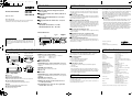
L73R2_XE(GB).fm English 1 ページ Français 2003年4月23日 水曜日 午後2時17分 Deutsch FEATURES VCB-3385P VCB-3380P VCB-3380P-UK INSTRUCTION MANUAL B/W CCD camera PRECAUTIONS ■ Backlight compensation ■ 1/3-inch CCD solid-state image device (about 470,000 pixels) ■ Horizontal resolution of 570 TV lines, S/N ratio of 50 dB min. ■ Minimum required illumination of 0.07 lx (F1.2 lens, 50 IRE) About this manual ■ High speed electronic shutter: 1/50 – 1/100,000 sec. Before installing and using the camera, please read this manual carefully. Be sure to keep it handy for later reference. ■ Power supply VCB-3385P: 24 V AC and 12 – 15 V DC VCB-3380P/3380P-UK: 220 – 240 V AC ■ In case of problem ■ Protect from high temperatures Do not use the camera if smoke or a strange odor comes from the unit, or if it seems not to function correctly. Disconnect the power cord immediately, and consult your dealer or a Sanyo Authorized Service Center. Do not install close to stoves, or other heat generating devices, such as spotlights, etc., or where it could be subject to direct sunlight, as that could cause deformation, discoloration or other damages. Be careful when installing close to the ceiling, in a kitchen or boiler room, as the temperature may raise to high levels. Install where the temperature range will stay between –10°C (14°F) and 50°C (122°F). (no condensation) ■ Do not open or modify Do not open the cabinet, as it may be dangerous and cause damage to the unit. For internal settings and repairs, consult your dealer or a Sanyo Authorized Service Center. ■ Do not put objects inside the unit Make sure that no metal objects or flammable substance get inside the camera. If used with a foreign object inside, it could cause a fire, short-circuits or damages. If water or a liquid gets inside the camera, disconnect the power cord immediately, and consult your dealer or a Sanyo Authorized Service Center. Be careful to protect the camera from rain, sea water, etc. ■ Be careful when handling the unit ■ Cleaning • Dirt can be removed from the cabinet by wiping it with a soft cloth. To remove stains, wipe with a soft cloth moistened with a soft detergent solution and wrung dry, then wipe dry with dry soft cloth. • Do not use benzine, thinner or other chemical product on the cabinet, as that may cause deformation and paint peeling. Before using a chemical cloth, make sure to read all accompanying instructions. Make sure that no plastic or rubber material comes in contact with the cabinet for a long period of time, as that may cause damage or paint peeling. To prevent damages, do not drop the camera or subject it to strong shock or vibration. External dimensions ■ Install away from electric or magnetic fields VCB-3385P 121.3 109.5 0.5 VCB-3380P VCB-3380P-UK 57 57 If installed close to a TV, radio transmitter, magnet, electric motor, transformer, audio speakers the magnetic field they generate will distort the image. ■ Protect from humidity and dust Depending on the conditions of use, installation and environment, please be sure to make the appropriate settings and adjustments. If you need help with installation and/or settings, please consult your dealer. 45 45 To prevent damages to the camera, do not install it where there is greasy smoke or steam, where the dampness may get too high, or where there is a lot of dust. 41.7 1AC6P1P2707-L73R2/XE, L73R5/XE, UK (0503TR-KP-TTC) 1/4"-20 UNC 14 NAMES AND FUNCTIONS OF PARTS <Figure 1. Right view:> 1 2 <Figure 3. Rear view:> 3 VCB-3380P/3380P-UK 9 7 5 <Figure 2. Left view:> VCB-3385P 6 1 2 3 TROUBLESHOOTING <Figure 2. Left view:> 6 LENS (lens iris output terminal) Used to connect the lens plug when the lens is attached. 1Brake coil (–) 3Drive coil (+) 2Brake coil (+) 4Drive coil (–) 7 G 8 F 7 VIDEO OUT (video output terminal: BNC connector) ■ If the image is unclear Connects to the VIDEO IN (video input) terminal on the peripheral equipment. • Is the lens in focus? Is the flange back distance adjusted correctly? • Is the lens dirty? Dirt or fingerprints on the lens can adversely affect the image. Gently wipe any dirt or fingerprints off the lens with a soft cloth or lens cleaning paper and cleaning fluid (commercially available). • Is the monitor adjusted correctly? 8 POWER (power indicator) Lights (red) when the camera power is ON. 9 Power cord ■ VCB-3385P <Figure 1. Right view:> 7 VIDEO OUT (video output terminal: BNC connector) 1 Lens cap Protects the lens from damage. Connects to the VIDEO IN (video input) terminal on the peripheral equipment. 2 Flange-back adjustment dial 8 POWER (power indicator) Adjusts the flange-back distance when a zoom lens is attached. Lights (red) when the camera power is ON. 3 Camera adjustment/setting panel F GND, AC24V, DC12V (ground terminal, 24 V AC or 12 V DC input terminal) 4 LOCK Locking screw for the flange-back adjustment dial. 5 Camera attachment bracket Used to attach the camera. ■ If no image appears ■ VCB-3380/3380P-UK 4 1 Contains camera adjustment dials and setting switches. Before sending the camera out for repair, check the items below. If the problem persists after checking these items, contact your place of purchase or a Sanyo Authorized Service Center. • • • • <Figure 3. Rear view:> 8 4 Printed on recycled paper 9 G VS IN (External sync composite video signal input terminal: BNC connector) Is the power ON? Is the coaxial cable attached securely? Are the power and voltage normal? Is there adequate illumination? SERVICE The camera is a precision instrument. Handle it carefully and always follow the safety precautions. If the camera requires service, never try to repair it yourself or open the casing. For servicing, maintenance, or repairs, contact your place of purchase or a Sanyo Authorized Service Center. SANYO Electric Co., Ltd. Printed in Taiwan SPECIFICATIONS Scanning system Interlace Image device Number of pixels Number of pixels in image area Sync system Resolution Video output terminal Image S/N ratio Electronic shutter speed Minimum required illumination Backlight compensation ON/OFF Auto-iris lens output Lens mount Flange-back Auto-iris lens switching Attachment screw hole diameter Operating environment Power supply Power consumption Weight Accessories : CCIR standard (625 scanning lines, 25 frames/second) : PLL 2: 1 interlace : 1/3-inch solid-state CCD : 795 (H) × 596 (V) : 752 (H) × 582 (V) : Internal sync/Line lock (manually switched) VCB-3385P only; External sync (automatically switched) : 570 TV lines : 1.0 V(p-p)/75 Ω, composite : 50 dB min. : 1/50 – 1/100,000 sec. : 0.07 lx approx. (with F1.2 lens, 50 IRE) : Set to “ON” or “OFF” : DC output (variable DC level), 4-pin terminal : CS mount : 12.5 mm (adjustment range: ±0.5 mm) : EI/VIDEO/DC : 1/4"-20UNC (top or bottom surface) : Ambient temperature: –10 to +50°C (14 to 122°F) Humidity: 90% RH max. : VCB-3380P/3380P-UK; 220 – 240 V AC/ 50 Hz VCB-3385P; 24 V AC/50 Hz, 12 – 15 V DC : VCB-3380P/3380P-UK; 3.5 W approx. VCB-3385P; 3.0 W approx. : VCB-3380P/3380P-UK; 490 g approx. VCB-3385P; 245 g approx. : VCB-3385P only; Clamping core (1 pc.) Appearance and specifications are subject to change without prior notice. L73R2_XE(GB).fm 2 ページ 2003年4月23日 水曜日 午後2時17分 CONNECTIONS, INSTALLATION ADJUSTMENT, SETTINGS Monitor The camera comes pre-adjusted and ready to install at time of factory shipment, but you may want to make adjustments or settings to adapt to the operating conditions or installation environment, if necessary. If you have trouble adjusting the camera, contact your place of purchase or a Sanyo Authorized Service Center. • The settings shown for switches to and are the settings at time of factory shipment. • Use a Phillips-head screwdriver to adjust dials and . Camera installation Camera screws (Shorter) VCB-3380P/3380P-UK Connections VIDEO OUT 3 1 220 – 240 V AC POWER VCB-3385P VIDEO OUT VS IN Figure A ES MODE POWER Bracket screws (Longer) GAMMA LL ES SHARP SPEED AGC BLC VIDEO L ON 24 V AC connection AC24V Digital video recorder or time-lapse VCR : VIDEO IN : VIDEO OUT DC12V AC24V 3 2 Figure 1 DC 2 ● What you will need • Peripheral equipment (such as monitor, digital video recorder or time-lapse VCR) • Cables for connecting peripheral equipment and camera (coaxial cables, connecting plugs) • Power adapter (24 V AC or 12 V DC) • Attachable lens (Auto-iris lens recommended.) ● Coaxial cables supported You can use any of the following coaxial cables: • RG-59U (3C-2V) Length: About 250 m max. • RG-6U (5C-2V) Length: About 500 m max. • RG-11U (7C-2V) Length: About 600 m max. • When connecting the power cable to the camera, check that the polarity is correct. • To prevent fire hazard any UL listed wire rated VW-1, should be used for the 24 V AC cable input terminal. • When using an RG-59U (3C-2V) cable, do not use it on piping or air wiring. • Select the cable to use according to the distance between the devices to connect. • If you use a cable other than the types above, the image or sync signal will be attenuated and will not be transmitted correctly. ● Attaching a lens The 1/3-inch DC-type, CS mount auto-iris lens (sold separately) is recommended. 3 3 ■ VCB-3380P/3380P-UK Insert the power cord into the wall outlet. The “POWER” indicator (red) lights. ■ VCB-3385P Insert the power adapter plug into the wall outlet. The “POWER” indicator (red) lights. B Camera installation ● Camera attachment bracket 1 As shown in Figure B above, you can remove the camera attachment bracket and reattach it to the camera bottom if you want to attach the camera to the top of an object. If you remove the camera attachment bracket, be sure to use the removed screws when reattaching it (other screws may not fit). Turn the lens slowly to attach it to the camera. Connect the lens plug to the LENS terminal. 3 CAUTION Connect the power cable. Secure the supplied clamping core to the power cable as shown in Figure A. <When using a 24 V AC adapter> Connect 3 wire grounded cable# (use 18AWG+) to the ground (GND) terminal as shown in Figure 1. <When using a 12 V DC adapter> Connect the cable as shown in Figure 2. CAUTION CAUTION 1 Remove the lens cap. 2 Attach the lens. ● Making connections 1 Connect the camera and peripheral equipment with cables. 2 ■ VCB-3385P only 2 • Depending on the type of lens, the shape of the lens plug may differ. In this case, contact the place of purchase or a Sanyo Authorized Service Center. • When attaching the lens, use a lens with a mount screw (L) that is less than 7 mm in length. If a lens that exceeds this size is used, the camera may be damaged and you may not be able to attach it correctly. • When attaching a C mount lens, attach the lens to the L camera after inserting the C mount ring (sold separately). CAUTION When using the camera attachment stand (sold separately), select a location that will be able to withstand the weight of the camera and stand for many years, and fix them securely in place. Backlight compensation OFF ★ No backlight compensation is applied. Sync setting (LL) Vertical sync disturbance may occur when a selector is used to switch between multiple cameras connected to one monitor. To prevent vertical sync disturbance, set to “ON”. ON Line-Lock • Adjust PHASE dial to eliminate sync disturbance. OFF ★ Internal Sync 1 2 3 4 5 6 7 8 9 CAUTION 10 ● Camera adjustment/Settings If the image disturbance doesn’t disappear after adjusting the PHASE dial () on the second and subsequent cameras, adjust the PHASE dial () on the first camera. If the problem persists, check that all the devices have been connected with the correct power cable polarity. Line phase (PHASE) (★ = Factory default setting) A Connections ON PHASE LEVEL 3 Figure 2 For adjusting backlight compensation. Use this setting to adjust the backlight compensation when an image is backlit. • Line-Lock: Synchronizes the unit with power frequency. GND DC12V EI OFF 12 V DC connection GND H Backlight compensation (BLC) When sync setting () is ON, use a Phillips-head screwdriver to adjust the line phase. Electronic Shutter mode (ES MODE) ON Set the electronic shutter speed to the desired setting. (See ) OFF ★ Use the standard shutter speed (1/50 sec.). Electronic Shutter speed (ES SPEED) When electronic shutter mode is set to ON, a combination of the three settings can be used to set up to eight speed levels. Center Right Lens iris (LEVEL) When using a DC-type auto-iris lens, adjust the LEVEL dial if the entire image is too dark or too bright. L (Low) Closes the lens iris, making the entire image darker. H (High) Opens the lens iris, making the entire image brighter. Lens switching Set this as appropriate for the type of lens you are using. Shutter speed Left 1/120 ON ★ ON ★ ON ★ EI Electronic iris lens 1/250 ON ON OFF VIDEO Video auto-iris lens (lens with built-in amp circuits) 1/500 ON OFF ON DC ★ 1/1000 ON OFF OFF DC-type auto-iris lens (lens without built-in amp circuits, powered by DC power only) 1/2000 OFF ON ON 1/5000 OFF ON OFF 1/10000 OFF OFF ON 1/100000 OFF OFF OFF Outline compensation (SHARP) If object outlines appear too strongly, set to “OFF”. ON ★ Emphasizes object outlines. OFF Normal setting Gain control (AGC) For adjusting the sensitivity of the camera. Use this setting for shooting in dark environments. ON ★ Increased sensitivity allows shots to be taken in dark environments. OFF Normal setting Gamma compensation (GAMMA) For adjusting the gamma compensation. Use this setting to adjust the signal correction/contrast so that the image looks natural. ON ★ γ = 0.45 OFF No gamma compensation is applied. (γ = 1) CAUTION When using a video auto-iris lens • Turn the ALC (light control) dial on the lens barrel fully to AV (average). • If the backlight compensation is not correct, adjust the LEVEL dial on the lens barrel. ● Flange-back adjustment (only when zoom lens is attached) Flange back is the distance between the lens and the camera (CCD). Follow the steps below to adjust the flange back distance, since the image can become out of focus when you are zoomed-in on an object. 1 Loosen the LOCK screw 2 3 4 3 with a Phillips-head screwdriver. Zoom-in with the zoom lens, and adjust the focus 2 1 with the focus ring on the LOCK lens. 4 Set the zoom lens to wide angle, and adjust the focus with the flange-back adjustment dial. Repeat steps 2 and 3 to check that the focus is not lost when switching between wide-angle and zoom, and then tighten the LOCK screw.