1
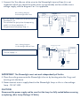
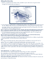
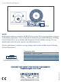
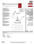
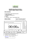
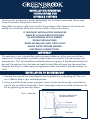
INSTALLATION/OPERATING
INSTRUCTIONS FOR
C100SLK & C100TSLK
Thank you for purchasing a quality Showerlight Fan Kit from Greenbrook. Please read
these instructions fully prior to initial use.
Every effort has been made to ensure that the guidance information on this sheet will
enable the installation of the fan to be carried out safely and correctly.
IF IN DOUBT, INSTALLATION SHOULD BE
MADE BY A QUALIFIED ELECTRICIAN
IN ACCORDANCE WITH CURRENT
WIRING REGULATIONS.
WHEN INSTALLING FANS, SWITCH OFF
MAINS SUPPLY BEFORE MAKING
ELECTRICAL CONNECTIONS.
IMPORTANT
The appliance is not intended for use by younger children or infirm persons without
supervision. Young children should be supervised to ensure that they do not play with
the appliance. This fan should be installed by fixed wiring only. A flexible cord should not
be used. Precautions must be taken to avoid the back-flow of gases into the room from
the open flue of gas or other open-fire appliances when mounted in outside windows or
walls.
INSTALLATION OF SHOWERLIGHT
1. Remove the cover of the showerlight by twisting clockwise and pulling off. Then cut
out a 108mm hole in your selected position.
2. Using two of the fixing screws provided, screw into the two fixing clips and slide the
clips to the rear of the showerlight. Push showerlight into cut out hole and secure the
fan by tightening the two clip screws.
Dia 1- Sideview
Showerlight
3. Connect the Transformer white wires to the Showerlight terminal box (it is not
important which way round the white wires are connected) and to suitable mains
voltage supply, refer to diagram 2 or 3 as applicable.
Dia 2- Wiring Diagram
for Showerlight with Timer
Ceiling junction box
Timer Fans require 3 fixed wires to be connected
1. The Neutral = N
2. The switched live (only when the operating
switch is in the on position) = T
3. The permanent live (always live) = L
Blue
Wire
Brown
Wire
Terminal
Box
Showerlight
Dia 3- Wiring Diagram
for Showerlight without Timer
1. The Neutral = N
2. The live supply = L
Ceiling junction box
L
L
Brown
Wire
Blue
Wire
Terminal
Box
Showerlight
IMPORTANT: The Showerlight must not work independently of the fan.
4. Place the ceiling cover onto the Showerlight chassis by locating onto the 3 lugs and
twisting anti-clockwise.
5. Never connect mains supply direct to the Showerlight lamp as this is a low voltage
lamp - 12V AC 35W
CAUTION
Disconnect the power supply and be sure that the lamp has fully cooled before removing
or replacing. (Max Lamp Wattage 35 Watts)
Fitting the Inline Fan
1. Select a suitable place for the fan to be screwed to a joist and secure using two screws
through the fixing bracket see diagram 4.
Dia 4- Ducting Diagram
Showerlight
2. Using the external grille select a suitable position either in the soffit or on an outside wall and
cut a 4”/103mm hole. Attach one end of the flexible duct to the grille with one of the straps
provided and from the outside feed the ducting through the hole until the grille is flush with
the soffit/wall. Secure the grille to the wall.
N.B. It is best not to cut the flexible ducting until the grille with the flexible ducting attached has
been screwed to the outside surface so as to avoid the possibility of cutting the duct to short.
3. Pull the flexible ducting gently to the discharge spigot of the fan and cut it to length and
connect to the fan with another of the straps provided.
N.B. The discharge end of the fan unit is the end where you can see the fan blade clearly.
There is also an arrow on the unit showing the airflow direction.
4. Connect the other piece of duct to the Showerlight and onto the fan as before using the other
straps provided. Cut off and discard any excess ducting.
Note
All wiring must be fixed securely and the cable to the fan should be a minimum of 1mm2 in
section. This unit is double insulated and therefore does not require an earth.
The time delay is preset for approximately two minutes and can be adjusted as described in the
‘Timer Adjustment’ section below (For C100TSLK model only). Try to keep the ducting as straight
as possible and wherever possible keep the distance between the ceiling grille and the external
soffit or wall as short as possible as the shorter the length of ducting the better the performance
of the fan.
Timer Adjustment - For C100TSLK model only
The Timer fan will run approximately two minutes after it has been switched off.
This time delay can be increased by firstly switching off the power to the fan.
Remove the timer cover and using a small screwdriver carefully turn the small control adjuster
clockwise to reduce the time and anti-clockwise to increase the time.
Only adjust with power switched off. The Timer will run for a minimum of about 2 minutes and
the maximum is about 30 minutes.
Dia 5- Timer Control Diagram
N T
L
NOTE
All electrical work must conform to BS7671 the current IEE wiring regulations and part
P of building regulations. You are advised to check with your local authority’s Building
Control Department, or an Authorised Competent Person, before starting. If in any
doubt about electrical work, contact a qualified electrician.
A direct replacement, without a wiring change, need not be notified to your Building
Control Department.
TECHNICAL DATA
Is a Brand Name of
GreenBrook Electrical PLC
Rated Voltage:
Load:
IP Rating:
Air movement:
Insulated:
230V, AC
50Hz
35W Maximum (Light) 20W (Fan)
IP44
Up to 95 Cubic Metres/Hour (26.7 Litres/Sec)
Class II Double
PLEASE KEEP THESE INSTRUCTIONS SAFE FOR FUTURE REFERENCE
GreenBrook Helpline : 01279 772 736
Issue no: 701728
WEST ROAD . HARLOW
ESSEX . CM20 2BG . UK
[email protected]
WWW.GREENBROOK.CO.UK