1
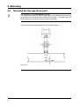
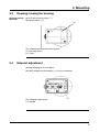
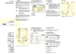
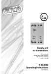
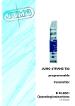
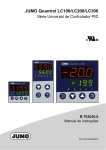
Flue gas Thermostat
Type STM-RW-2
B 60.1540.0
Operating Instructions
10.03/00329536
Please read these Operating Instructions before commissioning the instrument. Keep the
manual in a place that is accessible to all users at all times. Please assist us to improve
these operating instructions, where necessary. Your suggestions will be appreciated.
Phone +49 661 6003-0
Fax
+49 661 6003-607
All necessary settings, and where appropriate, alterations inside the instrument are
described in these operating instructions. However, if any difficulties should still arise during commissioning, you are asked not to carry out any unauthorized manipulations on the
unit. You could endanger your rights under the instrument warranty! Please contact the
nearest subsidiary or the head office in such a case.
Contents
1
Introduction
4
1.1 Typographical conventions ......................................................................... 4
1.1.1 Warning signs ................................................................................................. 4
1.1.2 Note signs ...................................................................................................... 4
1.2
Application .................................................................................................... 5
2
Instrument identification
2.1
Nameplate ..................................................................................................... 6
2.2
Type designation .......................................................................................... 6
3
Mounting
3.1
Dimensions ................................................................................................... 7
3.2
Mounting the flue gas thermostat .............................................................. 8
3.3
Opening / closing the housing .................................................................... 9
3.4
Setpoint adjustment ..................................................................................... 9
4
Installation
4.1
Regulations and notes ............................................................................... 10
4.2
Electrical connection ................................................................................. 10
5
Instrument description
5.1
Technical data ............................................................................................. 11
5.2
Maintenance/fault ...................................................................................... 11
6
7
10
11
1 Introduction
1.1
Typographical conventions
1.1.1
Warning signs
V
Danger
A
1.1.2
H
v
abc1
This sign is used when there may be danger to personnel if the instructions
are ignored or not followed correctly!
Caution
This sign is used when there may be damage to equipment if the instructions
are ignored or not followed correctly!
Note signs
Note
This sign is used when your special attention is drawn to a remark.
Reference
This sign refers to further information in other chapters or sections.
Footnote
Footnotes are remarks that refer to specific points in the text. Footnotes
consist of two parts:
Marking in the text and the footnote text.
The marking in the text is arranged as continuous superscript numbers.
The footnote text (in smaller typeface) is placed at the bottom of the page and
starts with a superscript number.
✱
Action
This sign indicates that an action to be performed is described.
The individual steps are marked by this asterisk, e. g.
✱ Open housing
4
1 Introduction
1.2
Application
The flue gas thermostat is used for monitoring flue gas temperatures on solidfuel boilers in dual operation with oil-heated boilers.
A
Operation
Caution
When burning solid fuels, it is necessary to ensure that they are approved in
accordance with the corresponding local regulations on emission protection. If
this is ignored, corrosive gases may destroy the thermostat!
The flue gas thermostat operates on the principle of rod expansion. The
immersion tube and the metal rod inside it have different expansion coefficients, producing a temperature-dependent difference in length which acts on
the microswitch through a mechanism. The microswitch is operated above a
set temperature limit. After the immersion tube has cooled down by approx. 10
to 30 °C, the microswitch is reset. Should the immersion tube break, the circuit
is opened permanently.
5
2 Instrument identification
2.1
Nameplate
Fig. 1 Nameplate
✱ Identify the instrument type by the nameplate and the type designation
2.2
Type designation
STM -RW -2
STM
-RW
-2
Basic type
rod thermostat with microswitch
flue gas temperature monitor (ATW) with changeover
contact
with internal scale
STM -RW -2 /OS Extra code
/OS as STM-RW-2, but microswitch with 2 separate circuits
1 x break contact (n.c.)
1 x make contact (n.o.)
6
3 Mounting
A
H
3.1
e
The installation must be run down before mounting the flue gas thermostat
Type STM-RW-2 !
The mounting site should be easily accessible and as far as possible free from
shock and vibration.
The permissible ambient temperature must be observed (note possible radiant
heat).
Dimensions
Fig. 2 Type STM-RW-2
7
3 Mounting
3.2
A
Mounting the flue gas thermostat
The thermostat is installed without a pocket.
The temperature probe must be at right angles to the flow direction and must
be exposed to the flue gas for its entire active length. The probe end must
have a clearance of at least 10 mm in the axial direction.
h Secure the flue gas thermostat by its G 1/2 pipe thread.
Fig. 3 Installation of temperature probe
8
3 Mounting
3.3
Opening/closing the housing
Opening/closing
the cover
✱ Unscrew housing screws ( 1 )
✱ Remove cover ( 2 ).
(2)
( 1) )
(1
( 1) )
(1
Fig. 4 Opening/closing the housing cover
( 1 ) Housing screws
( 2 ) Cover
3.4
Setpoint adjustment
✱ Open housing cover, see above
✱ Adjust setpoint on the spindle ( 1 ) using a screwdriver.
Fig. 5 Setpoint adjustment
(1)
( 1 ) Spindle
9
4 Installation
4.1
Regulations and notes
❏ The electrical connection must only be carried out by properly qualified personnel.
❏ The choice of cable, the installation and the electrical connection must conform to the requirements of VDE 0100 “Regulations on the Installation of
Power Circuits with nominal voltages below 1000 V” or the appropriate
local regulations.
❏ If contact with live parts is possible while working on the unit, it must be
completely disconnected from the supply.
❏ Earth the instrument at the PE terminal with the protective earth conductor.
This cable must have at least the same cross-section as used for the supply
cables. Earth cables must be wired in a star configuration to a common
earth point that is connected to the protective earth of the supply. Do not
loop earth cables, i.e. do not run them from one instrument to another.
4.2
Electrical connection
✱ Make connection according to the connection diagram
Fig. 6 Type STM-RW-2
Fig. 7 Type STM-RW-2/OS
10
5 Instrument description
5.1
Technical data
Limit range
standard: +40°C to +120°C (factory-set to +100°C)
special version: +20°C to +400°C (factory-set to +120°C)
Permissible
ambient
temperature
at probe: max. +700°C
Contact rating
10(2) A, 230 V AC, p.f. = 1(0.6)
0.25 A, 230 V DC
Switching
differential
Switching point
accuracy
referred to
switch-off point
at thermostat head: max. +80°C, min. -50°C
Limit range
+40°C to +120°C
+20°C to +400°C
STM-RW-2
10 to 18°C
10 to 22°C
STM-RW-2/OS
10 to 30°C
10 to 40°C
Limit range
Scale start
+40°C to +120°C
+ 0°C
–10°C
+ 0°C
–15°C
Scale end
+ 0°C
–10°C
+20°C to +400°C
+ 0°C
–20°C
Mean ambient
temperature
error
switching point displacement,
referred to the deviation from +22°C ~ 0.07 °C/°C
Protection
IP54 to EN 60 529, operation under normal conditions
Fusing
required
16 A
Operating
medium
flue gas
Time constant
≤ 45 sec
Operating
position
to DIN 16 257, NL0 — NL90 (other NL on request)
Action
to EN 60 730-1
Type 2BL= automatic action with micro switch-off in operation,
no auxiliary energy supply required.
5.2
Maintenance/fault
The flue gas thermostat requires no maintenance. In the event of a fault,
please contact your supplier or the head office (see back cover for address).
11
JUMO GmbH & Co. KG
JUMO Instrument Co. Ltd.
JUMO PROCESS CONTROL INC.
Street address:
Moltkestraße 13 - 31
36039 Fulda, Germany
Delivery address:
Mackenrodtstraße 14
36039 Fulda, Germany
Postal address:
36035 Fulda, Germany
Phone: +49 661 6003-0
Fax:
+49 661 6003-607
e-mail: [email protected]
Internet: www.jumo.net
JUMO House
Temple Bank, Riverway
Harlow, Essex CM20 2TT, UK
Phone: +44 1279 635533
Fax:
+44 1279 635262
e-mail: [email protected]
Internet: www.jumo.co.uk
885 Fox Chase, Suite 103
Coatesville, PA 19320, USA
Phone: 610-380-8002
1-800-554-JUMO
Fax:
610-380-8009
e-mail: [email protected]
Internet: www.JumoUSA.com