1
Operating Instructions
Fresh air - Drying cabinet
in explosion-proof version
04/2002
VFT 60/90
Valid for:
Vötsch Industrietechnik GmbH
Bereich - Wärmetechnik
D-35447 Reiskirchen Greizer Straße 41-49
Phone 0049 (0) 6408 / 84-73 Telefax 0049 (0) 6408 / 84-8732
Operating Instructions für Fresh air - Drying cabinet VFT 60/90
P:\FM\VFT\Stammdatei_GB.fm
Fresh air - Drying cabinet VFT 60/90
Approval-no.:
Unit-no.:
Production year:
Installation location:
TÜV 02 ATEX 1826X
59 526......... 0010
2004
operation locations in hazardous areas
zone 2
Rated temperature:
...... °C
Permissible working temperature: ...... °C
Temperature class:
Rated power:
10,0 kW
Input power:
Rated current:
16,7 A
Connection diagram:
Voltage:
400V / 3N / PE / 50Hz
Total vapour volume:
0,4 m³
Working space:
Flow rate:
2 m³/min
air changes/min.:
II 3G EEx n A P II T ...
Read the Operating Instructions, observe them and keep them close to the device!
T ...
11,0 kW
83066
0,35 m³
about 5
Operating Instructions für Fresh air - Drying cabinet VFT 60/90
P:\FM\VFT\Stammdatei_GB.fm
04/2002
0
CONTENTS
Section
Title
Page
0
Contents
3)
1
Important notice / range
5)
1.1
1.2
1.3
1.4
1.5
1.6
Use according to the regulations
Demands to the production manager
Instruction book
Charging instruction
Guarantee
Special marking / danger indications
5)
6)
6)
6)
7)
9)
2
Description of the unit
11)
2.1
2.2
2.3
2.4
2.5
2.6
Description of the items
Structure
Function
Technical data
Electrical equipment of the unit
Mechanical equipment of the unit
11)
12)
13)
15)
17)
18)
3
Safety appliances
19)
3.1
3.2
3.3
3.4
3.5
3.6
Control of the extracted air flow rate
Fresh air fan
Control of the internal pressure of the switchbox
Door switch
Temperature limitation
Other Safety Appliances
19)
19)
20)
20)
21)
22)
4
Erection and installation
23)
4.1
4.2
4.3
4.4
4.5
4.6
4.7
4.8
4.9
Transport
Erection
Erection drawing
RI-Flow diagram
Connection of the supply and exhaust air conductions
Electrical Connection
Connection of the compressed air
Disassembly
Disposal
23)
24)
27)
28)
29)
32)
33)
34)
34)
5
Operation
35)
5.1
5.2
5.3
5.4
5.5
5.6
Working rules / Safety notes
Reaction at malfunctions
Switchboard
Rear side of switchboard
First commissioning
Operating the device
35)
36)
37)
38)
39)
45)
3 of 76
Title
Page
6
Error diagnosis
53)
7
Maintenance
55)
7.1
7.2
7.3
7.4
Testing and maintenance
Repeating inspections
Repair
Cleaning
55)
56)
63)
69)
8
Connection diagram
71)
8.1
Spare parts list of the switch box
71)
9
Spare parts list
73)
10
Documentation
75)
Operating Instructions für Fresh air - Drying cabinet VFT 60/90
P:\FM\VFT\Stammdatei_GB.fm
04/2002
Section
4 of 76
Important notice / range
1
IMPORTANT NOTICE / RANGE
Read carefully and observe these operating instructions before erecting and commissioning the unit to avoid errors and the damages caused by them.
Keep the operating instructions close to the device.
1.1
Use according to the regulations
The electrically heated fresh air drying cabinet model VFT is exclusively suitable
for:
Drying and heat treatment of materials emitting vapours and gases which could form
an explosive atmosphere with air.
Combustible materials of the explosion group II A and II B may be used here.
Interior space:
The interior space is explosion proof, corresponding to the ignition temperature
classes T2, T3 and T4 and corresponds to the requirements of the device group II,
category 2G.
Erection location:
The outside of the unit corresponds to the requirements of the device group II, category 2G.
A forbidden use which is not corresponding to its intended purpose is given at:
04/2002
Heating and storing of materials of the explosion group II C and explosive materials.
Heating of closed containers which are pressurised or could build up a pressure by
heating.
Heating and storing of foodstuffs.
Enabling the stay of living beings in the dryer and risking their life by that.
If you have doubts about special heat treatment applications please contact us.
Operating Instructions für Fresh air - Drying cabinet VFT 60/90
P:\FM\VFT\Stammdatei_GB.fm
Note:
The unit was set in factory to the ignition temperature class requested by the customer
(T2, T3 or T4) and this is marked on the unit.
A change / resetting of the ignition temperature class is only possible to be done by the
Vötsch-service personnel.
5 of 76
Important notice / range
1.2
Demands to the production manager
The unit must be operated only by instructed personnel.
Based on these Operating Instructions the production manager has to prepare a corresponding instruction book.
This instruction book has to consider the individual local and working conditions and the
language of the operators.
The production manager has to guarantee that all persons working on the unit (dryer)
are familiar with the safety information and observe them.
Work on electrical installations and components has to be carried out only by a skilled
electrician.
1.3
Instruction book
According to the Guideline 1999/92/EC some actions have to be taken for the protection
of the health and the safety of the employees:
The preparation of an explosion protection document is required according to article 8.
Within the scope of the risk evaluation required in this article, an estimation of the maximum charge to be loaded has to be carried out.
Charging instruction
The production manager has to establish a charging instruction for each dryer about the
maximum admissible charge depending on the charging material.
Note:
The production manager has to provide the instruction book and the charging instruction
for the operators and has to make sure that it is observed e. g. by regular training and
instruction of the personnel.
Operating Instructions für Fresh air - Drying cabinet VFT 60/90
P:\FM\VFT\Stammdatei_GB.fm
1.4
04/2002
This may be done e.g. according to ZH 1/10, section E 1.3.4.2, Technical Ventilation!
For the estimation according to ZH 1/10 the parameter for the quality factor for the survey of the quality of the air circulation is to be taken as f = 1 and for the safety factor as
kadm = 0,7.
6 of 76
Important notice / range
1.5
Guarantee
The unit must not be changed in the version as it was supplied by us.
A guarantee will only be granted if you act according to the directions of these Operating
Instructions.
The processes of development, production and shipping are according to the regulations
of DIN ISO 9001.
The safety and serviceability of the equipment is only guaranteed if the necessary maintenance and repair works are carried out by either our service engineers or by authorised skilled personnel.
We recommend to conclude a maintenance contract with our service department.
Maintenance and cleaning may be carried out by customer's specialised people.
→ please see section “7 Maintenance” (page 55)
Only original spare parts are to be used at maintenance and repair work.
The device was designed, manufactured and checked before delivery according to the
regulations of the EC.
Certificate of Conformity / Declaration of Manufacturer:
→ please see section “10 Documentation” (page 75)
The unit was set in factory to the ignition temperature class requested by the customer
(T2, T3 or T4) and this is marked on the unit.
A change / resetting of the ignition temperature class is only possible to be done by the
Vötsch-service personnel.
Operating Instructions für Fresh air - Drying cabinet VFT 60/90
P:\FM\VFT\Stammdatei_GB.fm
04/2002
The explosion protection measures are approved and certified corresponding to the EC
prototype test.
7 of 76
Important notice / range
The device corresponds to the safety requirements:
EC machine guideline
98/37/EG
Low tension guideline
73/23/EWG
Dryers and ovens
safety requirements
EN 746-1
Safety of machines
EN 12100-1 (2003)
EN 12100-2 (2003)
Safety in
electric-heating installations
EN 60519-1 EN 60519-2
Electrical equipment
of units
EN 60204-1
EN 61000-6-4
EN 61000-6-2
Explosive atmospheres
explosion protection
EN 1127-1
Electric resources for
hazardous areas
EN 50021 N
Installation of electric equipment
in hazardous areas
EN 60079-14
Guideline for the adjustment of the
Guideline 94 / 9 / EG
legal regulations of the member countries
for units and protection systems for the use
according to the regulations in hazardous
areas
(Explosion protection order, ATEX 100a)
04/2002
Electromagnetic compatibility
noise emission
noise immunity
Operating Instructions für Fresh air - Drying cabinet VFT 60/90
P:\FM\VFT\Stammdatei_GB.fm
The erection and installation of the unit in connection with an correctly executed and
properly working ventilation installed by the customer is crucial for the safety against
explosions!
8 of 76
Important notice / range
1.6
Special marking / danger indications
ATTENTION / DANGER
If these instructions are not observed this may lead to a hazard for the life of human
beings and other living beings of the environment, or to damages of the unit or the loading material.
ELECTRIC POWER
It is used to draw the attention to electric power.
Access to this area is only allowed to skilled electricians.
NOTE
It is used to indicate a support.
HOT SURFACE
The air of the drying space and the parts getting in contact with the air of the drying room
may be very hot.
Wear protective clothing (protective gloves)
INJURIES OF THE HANDS
A general danger of injuries like cutting or contusion is indicated.
Wear protective gloves!
04/2002
DANGER OF EXPLOSION
An explosion may occur if the instructions are not observed.
EXPLOSION PROOF INSTALLATION
Special installations are indicated which have an explosion protection.
Abbreviations
EN
= Europäische Norm
= European Standard
Operating Instructions für Fresh air - Drying cabinet VFT 60/90
P:\FM\VFT\Stammdatei_GB.fm
EMV = Elektro-Magnetische-Verträglichkeit
= Electromagnetic Compatibility
9 of 76
Operating Instructions für Fresh air - Drying cabinet VFT 60/90
P:\FM\VFT\Stammdatei_GB.fm
04/2002
Important notice / range
10 of 76
Description of the unit
2
DESCRIPTION OF THE UNIT
2.1
Description of the items
(Description of the standard unit without additional equipment)
Operating Instructions für Fresh air - Drying cabinet VFT 60/90
P:\FM\VFT\Stammdatei_GB.fm
04/2002
1
2
3
4
5
6
7
8
9
10
11
12
13
14
15
16
17
18
19
20
21
22
23
24
25
26
27
1.)
Door
Door lock
Door switch
Switchbox
Temperature sensor
Screen rails
Angular support 1.)
Insert 1.)
Supply air fitting
Exhaust air fitting
Heater
Protection conductor connection
Check valve (fresh air)
Butterfly damper (fresh air)
Differential pressure switch (exhaust air)
Fresh air fan
Compressed air connection 1/2" female thread
Pressure-reducer “Compressed air connection”
Solenoid valve “Emergency flushing”
Throttle valve “Emergency flushing”
Pressure-reducer “Internal pressure switchbox”
Throttle valve “Internal pressure switchbox”
Differential pressure switch “Internal pressure switchbox”
Pressure gauge “Internal pressure switchbox”
Pressure-reducer “Internal pressure switchbox”
Throttle valve “Switchbox flushing”
Double 4/2-way valve “Switchbox flushing”
additional equipment
11 of 76
Description of the unit
Structure
Thermal insulation:
The heating and drying cabinet is a double-wall construction of steel metal sheet and
heat insulated with mineral fibre (110 mm).
External housing:
The external housing is made of galvanised steel sheet, lacquered and has a bottom
which can be under-run.
Interior housing:
The interior housing is made of stainless steel (material 1.4301) and is welded tight to
avoid the penetration of dissolvent fumes into the thermal insulation.
Temperature regulation:
The temperature of the working space is controlled by an electronic temperature regulating system with semiconductor switching elements.
Heating:
The electrical heating is done by tubular heating elements of stainless steel (material
1.4828).
Temperature limitation:
The temperature of the working pace is limited by an electronic Safety Temperature Limiter (STL).
The STL is installed inside of the switchbox.
Fresh air fan:
The fresh air fan is on the roof of the unit behind the switchbox.
Safety against explosions:
The safe operation of the unit is guaranteed by the technical ventilation.
04/2002
Vertical air guiding:
The air inlet is at the roof of the working space and the exhaust at the bottom of it.
Control of the extracted-air:
The extracted-air flow rate is controlled by two flow indicators (differential pressure flow
indicators).
Switchbox:
The Switchbox is constructed according to the safety principle of a simplified pressure
encapsulation and is provided continuously with compressed air during the operation of
the unit.
Pick-up of material:
There are notched rails mounted at the side of the working space for the pick-up of
angular supports.
Wire-mesh shelves and charging trays may be placed on the angular supports.
The floor of the working space cannot be loaded.
Total load of the notched rails, the wire-mesh shelves and of the charging trays.
→ please observe section “2.4 Technical data” (page 15)
Note:
If charging trays are placed on the angular supports, the angular supports have to be
changed.
The loading instruction for the charging trays has to be observed.
→ please observe section “5.1.1 Loading instruction for charging trays 1.)” (page 36)
12 of 76
Operating Instructions für Fresh air - Drying cabinet VFT 60/90
P:\FM\VFT\Stammdatei_GB.fm
2.2
Description of the unit
2.3
Function
The fresh air drying cabinet series VFT is designed and constructed according to the
valid guidelines and regulations.
Before operating the unit a compressed air supply has to be connected and opened by
the customer.
The compressed air pressurises the switchbox.
The pressure of the switchbox is monitored by a pressure switch securing the compressed air supply.
Without the compressed air, only the fresh air fan will be connected after switching on
the unit, the heating is not connected.
Before every connecting of the main switch we recommend to flush the switchbox sufficiently by means of the manual valve “Switchbox flushing” to exclude a possibly
enriched concentration of solvent in the switchbox.
→ please observe section “5.6.1 Manual flushing of the switchbox” (page 45)
At each start up by switching on the main switch with the door of the unit closed, the
heating is connected only after completion of the safety flushing time and the emergency
flushing with compressed air and with the exhaust running trouble-free.
When the safety flushing time with the exhaust running trouble-free is passed the emergency flushing with compressed air is disconnected.
The heating is connected next with delay. (Self-control of the STL).
When opening the door of the dryer the heating is switched off.
The fresh air fan keeps running.
04/2002
When the connected dryer is loaded with feeding material the and the doors are closed,
the feeding material in the working space is passed by fresh air.
The safety flushing time passes and the emergency flushing with compressed air is
started.
When the safety flushing time with the exhaust running trouble-free has passed the
emergency flushing with compressed air is disconnected.
Next the heating is connected with delay. (Self-control of the STL).
The running down of the safety flushing time and starting the emergency flushing with
compressed air is repeated at every closing of the door.
The fresh air blown in from a no-load area is guided over an electric heating and fed
steadily to the working space.
Operating Instructions für Fresh air - Drying cabinet VFT 60/90
P:\FM\VFT\Stammdatei_GB.fm
A multiple air exchange per minute in the working space of the dryer is guaranteed by
the fresh air fan.
This air exchange is important for the safety!
The temporary exceeding of the lower explosion limit is allowed in zone 1.
The extracted-air flow rate is controlled by flow switches (differential pressure flow
switches).
13 of 76
Operating Instructions für Fresh air - Drying cabinet VFT 60/90
P:\FM\VFT\Stammdatei_GB.fm
04/2002
Description of the unit
14 of 76
Description of the unit
2.4
Technical data
60/90
Interior space (Working space)
Interior dimensions
Width
Height
Depth
m3
0,350
mm
570
900
600
mm
820
1650
1200
Loading / carrying capacity
Interior housing
total
kg
150
Floor
kg
---
Exterior dimensions
Width
total
Height
Depth
Wire-mesh shelves
surface load
1.)
quantity
concentrated load
surface load
max.
kg
13
10
20
quantity
concentrated load
surface load
max.
kg
13
10
20
concentrated load
surface load
kg
50
150
Weight (net)
kg
325
Extracted-air flow rate
m3/h
120
Air changes / min
approximately
Compressed air supply
Connection cross section
Connection pressure
Working pressure
Internal pressure switchbox
bar
Safety flushing time (air exchange)
sec.
Total vapour volume
m3
Charging trays 1.)
Operating Instructions für Fresh air - Drying cabinet VFT 60/90
P:\FM\VFT\Stammdatei_GB.fm
04/2002
Gratings 1.)
1.)
mbar
additional equipment
15 of 76
5
½"
5 ... 8
4,5
1,0
120
0,400
Description of the unit
60/90
Sound pressure level (acc. to DIN 45635)
Normal operation
Emergency flushing with compressed air
dB(A)
Ignition temperature class
< 60
< 80
T1 - T4
Disconnecting temperature
Safety temperature limiter (STL)
Ignition temperature class T1 and T2
Ignition temperature class T3
Ignition temperature class T4
°C
Temperature limit cut-out (TLC) 1.)
Ignition temperature class T1 and T2
Ignition temperature class T3
Ignition temperature class T4
240
175
120
230
180
130
Temperature-Safety Class
(acc. to EN 60519-2)
Safety temperature Limiter (STL)
Temperature limit cut-out (TLC) 1.)
Installation and working space classification
Installation place (2,5 m in the door area)
Interior space
Limitation of rated value
Temperature controller
Ignition temperature class T1 and T2
Ignition temperature class T3
Ignition temperature class T4
Rated temperature
Ignition temperature class T1 and T2
Ignition temperature class T3
Ignition temperature class T4
cluster
category
2
2G
°C
200
150
100
°C
200
150
100
for differing data please see nameplate
V / Hz
400, 3/(N)PE, AC 50
Ignition temperature class T1, T2, T3 and T4
Rated current
Rated power
Input power
1.)
2
3G
additional equipment
16 of 76
A
kW
kW
16,7
10,0
11,0
Operating Instructions für Fresh air - Drying cabinet VFT 60/90
P:\FM\VFT\Stammdatei_GB.fm
Electrical data
Rated voltage / frequency
cluster
category
04/2002
2
2
Description of the unit
2.5
Electrical equipment of the unit
2.5.1 Temperature controller 2.)
Jumo dTRON 04.1
2.5.2 Temperature controller / Program controller 1.) 2.)
Jumo Dicon 501
2.5.3 Safety temperature limiter (STL) 2.)
Philips TB 40
2.5.4 Temperature limit cut-out (TLC) 1.)
Jumo iTRON
2.5.5 Door switch
Disconnecting of the heating when the door is opened.
Starting of an emergency flushing with subsequent connection of the heating after
closing the door.
2.5.6 Heating
Electric heating by means of stainless steel heating elements.
04/2002
2.5.7 Fresh air fan
The fresh air fan is an EEx version.
2.5.8 Extracted-air monitoring
Differential pressure switches monitor the extracted-air flow rate.
2.5.9 Monitoring of the internal pressure of the switchbox
Differential pressure switches monitors the pressure in the switchbox.
2.5.10Ex-separator amplifier
Galvanic separation of the differential pressure switches.
Operating Instructions für Fresh air - Drying cabinet VFT 60/90
P:\FM\VFT\Stammdatei_GB.fm
2.5.11Ex-transducer
Galvanic separation of the temperature sensors.
2.5.12Solenoid valve
Safety flushing of the heating and of the working space with compressed air when
the main switch, after every closing of the door and at all malfunctions, is connected
1.)
2.)
additional equipment
documentation of the equipment in section 10 Documentation
17 of 76
Description of the unit
Mechanical equipment of the unit
2.6.1 Pick-up of material
Notched rails
Mounted at the side for the pick-up of angular supports.
Total load of the notched rails
→ please observe section “2.4 Technical data” (page 15)
Floor of the working space
Not to be loaded
2.6.2 Door seal
silicone
viton 1.)
2.6.3 Throttle valve
There is an adjustable throttle valve in the fresh air feed line in front of the fresh air
fan.
2.6.5 Compressed air connection
Safety flushing of the heating and the working space with compressed air when
the main switch is connected, after every closing of the door and at all malfunctions.
Pressurising of the switchbox with compressed air.
04/2002
2.6.4 Check valve
There is check valve of stainless steel in the fresh air feed line in front of the fresh
air fan.
2.6.6 Hand valve switchbox flushing
Manual safety flushing of the switchbox with compressed air before each start up.
2.6.7 Angular support 1.)
For the pick-up of inserts.
2.6.8 Inserts 1.)
Wire-mesh shelves
Charging trays
Load of the wire-mesh shelves and of the charging trays
→ please observe section “2.4 Technical data” (page 15)
2.6.9 Lead-through 1.)
Gas-tight lead-through at the exterior wall for measuring in the interior space.
Version with blind flange DN 25 KF.
1.)
additional equipment
18 of 76
Operating Instructions für Fresh air - Drying cabinet VFT 60/90
P:\FM\VFT\Stammdatei_GB.fm
2.6
Safety appliances
3
SAFETY APPLIANCES
Do not make any manipulation at the safety appliances!
Every unauthorised intervention may have unforeseeable consequences.
Explosion hazard!
The function of the safety appliances has to be checked regularly.
→ please observe section “7.1 Testing and maintenance” (page 55)
3.1
Control of the extracted air flow rate
Differential pressure switch
Control of the extracted air flow rate necessary for a safe operation by two differential
pressure switches. (redundant control)
The differential pressure switches are connected with the corresponding switching
amplifier by explosion protected circuits (intrinsically safe).
When the minimum extracted air flow rate is underspent the differential pressure
switches disconnect the heating and initialise an emergency flushing of the heating
channel and the working space with compressed air.
The malfunction of the extracted air is signalised optically.
The reconnection of the heating is done only at the correct extracted air flow rate.
04/2002
After the return of the correct extracted air flow rate a safety flushing time runs down.
When the safety flushing time ran down without error the emergency flushing with compressed air is disconnected .
Subsequently the heating is connected with delay. (Auto control of the STL)
3.2
Fresh air fan
The fresh air fan is explosion proof according to
according to the PTB-certificate Ex-83/3638.
EEx e II T4 and is approved
Operating Instructions für Fresh air - Drying cabinet VFT 60/90
P:\FM\VFT\Stammdatei_GB.fm
The fresh air fan provides a constant fresh air flow rate.
This fresh air flow rate is streaming through the heating, the working space and is subsequently extracted through the exhaust gland.
19 of 76
Safety appliances
3.3
Control of the internal pressure of the switchbox
Differential pressure switch
Control of the of the internal pressure of the switchbox necessary for a safe operation,
by a differential pressure switch.
The Switchbox is constructed according to the safety principle of a simplified
pressure encapsulation and is pressurised continuously with compressed air
during the operation of the unit.
When the interior pressure of the switchbox is underspent e. g . when the compressed
air supply is interrupted, the differential pressure switch disconnects the complete control.
The fresh air fan continues running (fresh air flushing) in order to maintain the safety
principle of the unit.
The heating, the temperature control and the other controls are disconnected.
The solenoid valve of the safety flushing with compressed air is open.
The error of the interior pressure of the switchbox is signalled optically and acoustically.
The reconnection of the unit is done only at the correct interior pressure of the switchbox.
After the return of the compressed air a safety flushing time runs down and the safety
flushing of the heating channel and of the working spaces with compressed air is started.
When the safety flushing time ran down without error the emergency flushing with compressed air is disconnected .
Subsequently the heating is connected with delay. (Auto control of the STL)
The door switch has an explosion protection according to
II 2G EEx d IIC T6 and is
approved according to the PTB-test certificate 00ATEX 1006X.
Opening the door:
When the door is opened the heating is disconnected by the door switch.
The fresh air fan stays in operation.
04/2002
Door switch
Closing the door:
When the door is closed the safety flushing time is activated by the door switch and the
emergency flushing with compressed air is initiated.
When the safety flushing time ran down without error at the exhaust air the emergency
flushing with compressed air is disconnected.
Subsequently the heating is connected with delay. (Auto control of the STL).
The running down of the safety flushing time and the starting of the emergency flushing
with compressed air is repeated at every closing of the door.
20 of 76
Operating Instructions für Fresh air - Drying cabinet VFT 60/90
P:\FM\VFT\Stammdatei_GB.fm
3.4
Safety appliances
3.5
Temperature limitation
3.5.1 Safety temperature limiter (STL)
Device protection: (thermal safety class 2 acc. to EN 60519-2).
The safety temperature limiter is electrically and functionally independent of the regulating installation.
If the temperature set is exceeded the safety temperature limiter disconnects permanently the heating and initiates the emergency flushing of the heating channel and the
working space with compressed air.
The malfunction of the temperature is indicated optically.
Disconnecting temperatur: → please observe section “2.4 Technical data” (page 15)
Reset the safety temperature limiter:
The temperature error is reset by operating the key switch “reset” when the releasing
temperature is underspent.
After resetting the safety temperature limiter the emergency flushing with compressed
air is disconnected and the heating is connected.
Temperature errors, which cause a triggering of the safety temperature limiter are
important for the safety.
The device has to be checked to eliminate the reason for the temperature error for
the further operation.
3.5.2 Temperature limit cut-out (TLC) 1.)
04/2002
Material protection: (thermal safety class 2 acc. to EN 60519-2).
The temperature limit cut-out is electrically and functionally independent of the regulating installation.
If the temperature set is exceeded the temperature limit cut-out disconnects permanently the heating and initiates the emergency flushing of the heating channel and the
working space with compressed air.
The malfunction of the temperature is indicated optically.
Disconnecting temperatur: → please observe section “2.4 Technical data” (page 15)
Reset the selectable temperature limiter:
The temperature error is reset by operating the “P-push button” when the releasing temperature is underspent.
Operating Instructions für Fresh air - Drying cabinet VFT 60/90
P:\FM\VFT\Stammdatei_GB.fm
After resetting the temperature limit cut-out the emergency flushing with compressed air
is disconnected and the heating is connected.
1.)
additional equipment
21 of 76
Safety appliances
Other Safety Appliances
3.6.1 Main switch
Main switch lockable by a padlock.
3.6.2 Protective motor switch
Overload and short circuit protection of the fresh air fan, the heating and the control voltage by protective motor switches.
When a protective motor switch is triggered the heating is disconnected and the safety
emergency flushing of the heating channel and the working space with compressed air
is initiated.
The error is indicated optically.
3.6.3 Leakage current circuit breaker
Monitoring of not permissible leakage current of the heating at the housing by a leakage
current circuit breaker (FI = 30 mA).
If the leakage current circuit breaker is triggered the heating is disconnected and the
emergency flushing air of the heating channel and the working space with compressed
is initiated.
The error is indicated optically.
3.6.4 Ex- transducer
The Ex- transducer is explosion proof according to
[EEx ia] II C and is approved
according to the Test certificate BAS NR. Ex 94 C 2516.
3.6.5 Ex- separator amplifier
The Ex-separator amplifier is explosion proof according to
[EEx ia] II C and is
approved according to the PTB-Test certificate Ex-94.C.2086.
04/2002
Galvanic separation of the temperature sensor for the temperature controller and the
safety temperature limiter (STL).
Galvanic separation of the differential pressure switch for the extracted air monitoring.
3.6.6 Solenoid valve “Emergency flushing”
The solenoid valve “Emergency flushing” is explosion proof according to
EEx m II T4 and is approved according to the Test certificate INERIS 96.D 5058 X.
Safety flushing of the heating and of the working space with compressed air at a breakdown of the control, of the technical ventilation or its monitoring.
The solenoid valve “Emergency flushing” is opened when the current is switched off.
3.6.7 Manual valve “Switchbox flushing”
The manual valve of the switchbox flushing is a manual safety device.
Before every connecting of the main switch we recommend to flush the switchbox sufficiently by means of the manual valve “Switchbox flushing” to exclude a possibly
enriched concentration of solvent in the switchbox.
→ please observe section “5.6.1 Manual flushing of the switchbox” (page 45)
22 of 76
Operating Instructions für Fresh air - Drying cabinet VFT 60/90
P:\FM\VFT\Stammdatei_GB.fm
3.6
Erection and installation
4
ERECTION AND INSTALLATION
Qualified personnel is required for the transport, erection and installation of the unit!
The corresponding accident prevention rules have to be observed.
4.1
Transport
Shipment is done on a transport pallet.
Transport the unit to the erecting place with a fork lift or suitable lift truck.
Dead weight: → please observe section “2.4 Technical data” (page 15)
04/2002
Do not use belts for lifting or erecting the unit!
Unit with a bottom which can be under-run
Lift the unit carefully at the bottom from the pallet with a fork lift or suitable lift truck.
- Remove the pallet .
- Erect the unit at the erecting place.
→ please observe section “4.3 Erection drawing” (page 27)
Operating Instructions für Fresh air - Drying cabinet VFT 60/90
P:\FM\VFT\Stammdatei_GB.fm
We recommend: keep the pallet parts for service or move
23 of 76
Erection and installation
Erection
Erection place
The outside of the unit corresponds to the requirements of the device group II, category
3G.
It is allowed to install the unit in an hazardous area zone 2 if gases and vapours are
likely not to occur.
If they occur, this will be only seldom or for a short time.
Important note:
It is not allowed to install the unit in hazardous areas zone 1!
The ignition temperature class of the installation room and of the unit have to be matching.
Erecting room
T1
T1 + T2
T1 - T3
T1 - T4
Unit
T1 - T4
T2 - T3
T3 + T4
T4
Please observe the accident prevention rules.
Electric equipment in the area of the dryer (2,5 m) have to be suitable for the use in
zone 2.
temperature max. 40 °C
sufficiently aerated
distance from rear side / roof
→ please observe section “4.3 Erection drawing” (page 27)
04/2002
dry max. 70 % rel. humidity
supply- and exhaust air conducts
→ please observe section “4.5 Connection of the supply and exhaust air conductions” (page 29)
Keep the distances indicated in the erection drawing to avoid fire and local overheating
of the unit or its surroundings and to guarantee a trouble-free operation of it.
→ please observe section “4.3 Erection drawing” (page 27)
Operating Instructions für Fresh air - Drying cabinet VFT 60/90
P:\FM\VFT\Stammdatei_GB.fm
4.2
24 of 76
Erection and installation
Standard foundation
non-flammable in a periphery of at least 2,5 m
flush and horizontal
free of vibrations
please observe the loading capacity of the ground
Weight of the unit plus the weight of the charge.
→ please observe section “2.4 Technical data” (page 15)
Erecting area
electrically conductive (against dangerous electrostatic charging)
Operating Instructions für Fresh air - Drying cabinet VFT 60/90
P:\FM\VFT\Stammdatei_GB.fm
04/2002
temperature resistant erecting ground
25 of 76
Operating Instructions für Fresh air - Drying cabinet VFT 60/90
P:\FM\VFT\Stammdatei_GB.fm
04/2002
Erection and installation
26 of 76
Erection and installation
Erection drawing
Operating Instructions für Fresh air - Drying cabinet VFT 60/90
P:\FM\VFT\Stammdatei_GB.fm
04/2002
4.3
1
2
3
4
5
Supply air fitting DN 100
Exhaust air fitting DN 100
Compressed air connection 1/2" female thread, 5 ... 8 bar
Mains connection 400V/3/(N)PE, AC 50Hz / 32A / 5 x 6 mm²
Protective conductor connection
27 of 76
Erection and installation
04/2002
RI-Flow diagram
CG
FS_A_
PI
PS_A_
TIC
TS+A+
Door limit switch
Differential pressure switch (exhaust air)
Pressure gauge “Internal pressure switchbox”
Differential pressure switch “Internal pressure switchbox”
Temperature sensor
Safety temperature limiter (STL)
11
12
Check valve (fresh air)
Butterfly damper (fresh air)
21
22
23
24
25
26
27
28
29
Pressure-reducer “Compressed air connection”
Solenoid valve “Emergency flushing”
Throttle valve “Emergency flushing”
Pressure-reducer “Internal pressure switchbox”
Throttle valve “Internal pressure switchbox”
Pressure-reducer “Switchbox flushing”
Throttle valve “Switchbox flushing”
Double 4/2-way valve “Switchbox flushing”
Silencer
Druckluft
Frischluft
Abluft
neutral
Kunde / VIT
=
=
=
=
=
Compressed air
Fresh air
Exhaust air
Neutral
Customer / VIT
28 of 76
Operating Instructions für Fresh air - Drying cabinet VFT 60/90
P:\FM\VFT\Stammdatei_GB.fm
4.4
Erection and installation
4.5
Connection of the supply and exhaust air conductions
The connection of the supply and exhaust air conductions has to be done only by
qualified persons.
The total length of the directly connected supply and exhaust air conductions (NW
100) should not exceed 5 m with max. 3 tube bends (90°) (R > D).
An additional extension of the conductions reduces the extracted-air flow rate.
Supply and exhaust air conductions have to be installed separated from each other.
Check the extracted-air flow rate after finishing the installation and adjust it, if necessary with the mechanical throttle valve in the fresh air conduct.
Extracted-air flow rate: → please observe section “2.4 Technical data” (page 15)
If the extracted-air flow rate cannot be adjusted,
contact a service point of Vötsch (see appendix).
4.5.1 Supply air system
The supply air has to be taken from a neutral area which is free of dissolvent
vapours (non hazardous area).
The unit has to be connected to the customer´s supply air system.
The following has to be considered for the supply air conduct:
The connection has to be tight (NB 100).
The lowest operating temperature of the unit depends on the temperature of the supply air fed.
(Lowest operating temperature = supply air temperature + 5 K)
Operating Instructions für Fresh air - Drying cabinet VFT 60/90
P:\FM\VFT\Stammdatei_GB.fm
04/2002
The connection at the unit's side must not be loaded mechanically.
29 of 76
Erection and installation
4.5.2 Exhaust air system
Due to the dissolvent vapours and the thermal load the exhaust air has to be guided into the open air or a neutral area (non hazardous area), we recommend the
connection to customer's exhaust air system.
The unit has to be connected to a customer's exhaust air system.
For the discharge of the exhaust air the following has to be considered:
No possible ignition sources in the in the exhaust air conduction.
Observation of the respective national valid regulations for emission values.
The pipes of the exhaust air system have to be of incombustible material (e.g. metal).
They have to be installed in a way that no fire hazard could emerge from the developing temperature.
Surface temperatures
(Tsurface = operating temperature < nominal temperature)
A sufficient thermal insulation has to be provided
(e.g. pipe casing of mineral fibre)
A measuring orifice (d = 40mm) has to be installed in the exhaust air conduction at a
suitable or accessible place (in a straight tube section, about 1m behind the exhaust air
conduct).
This measuring orifice is necessary for the control of the extracted-air flow rate during
the maintenance, checking and service work.
By the installation of the pipes for exhaust air it has to be granted that eventually existing
condensate will not run back to the unit.
(Install the exhaust air conduction if possible with approximately 2% falling gradient from
the unit and drain the condensate specifically into e.g. a condensate trap).
04/2002
At the conduction installation care has to be taken that it is not possible that deposits
build up and that an easy cleaning of the exhaust air line is possible.
(Revision orifices, possibility to dismantle sections, etc.)
The exhaust air of the unit must not be brought together with fuel-gas.
Note:
We warn against a connection to an exhaust air system with extraction.
30 of 76
Operating Instructions für Fresh air - Drying cabinet VFT 60/90
P:\FM\VFT\Stammdatei_GB.fm
It is only allowed to guide the exhaust air into chimneys if these do not have a connection with fire places or other workshops.
The exhaust air can only be guided into ventilation shafts if these have a fire-resistant
separation to other workshops.
Erection and installation
4.5.3 Exhaust air systems without extraction
The unit has to be connected directly to an exhaust air line at systems without extraction.
It is only possible to connect always one unit to one exhaust air line.
The total resistance to flow with a NB 100 and a total length of 5 m with 3 tube bends
(90°) (deducting a possibly existing supply air line and fresh air filter) should not be
exceeded at this.
Operating Instructions für Fresh air - Drying cabinet VFT 60/90
P:\FM\VFT\Stammdatei_GB.fm
04/2002
Example for an exhaust air system without extraction:
1
2
3
4
5
Operating place in hazardous area
Dryer
Fresh air conduct
Exhaust air conduct
Thermal insulation
6
7
8
9
10
11
Operating place in non hazardous area
Tube bend
Roof bonnet, deflector bonnet
Branch
Shutoff valve for condensate
Condensate tank
31 of 76
Erection and installation
Electrical Connection
The electrical connection must be done only by skilled electricians.
The corresponding national regulations have to be observed for the electrical connection.
The network conditions have to be in accordance with the data on the nameplate.
Variations of the mains voltage max. ± 10 %
Observe the VDE- and technical connection regulations of the local electricity supply
company.
Connection to power supply with clockwise rotating field.
Information about mains connection and necessary fuse protection on the connection
diagram.
We recommend the connection by means of a leakage current protective switch (FI =
300 mA).
For the connection to the mains supply a cable 5 meters long is connected to the unit
with a pull relief on the unit side.
External connection of the protective conductor
There is a connection of the protective conductor for customer's potential on the rear
side of the unit.
Sense of rotation of the motor:
04/2002
The connection of the protective conductor has to be clean and free of varnish.
Check the sense of rotation of the fresh air fan:
- Watch the rotation indicating arrow.
Operating Instructions für Fresh air - Drying cabinet VFT 60/90
P:\FM\VFT\Stammdatei_GB.fm
4.6
32 of 76
Erection and installation
4.7
Connection of the compressed air
The connection of the compressed air supply must be done only by qualified persons.
The corresponding national regulations have to be observed for the connection of
compressed air.
Connect the compressed air at the rear side behind the switchbox.
The compressed air volume has to be ensured for a time of at least 5 minutes.
Connection pressure: → please observe section “2.4 Technical data” (page 15)
The use of a Pressure-reducer with maintenance unit for filtered and oil-free (condensate-free) compressed air is a must.
Operating Instructions für Fresh air - Drying cabinet VFT 60/90
P:\FM\VFT\Stammdatei_GB.fm
04/2002
Note:
If nitrogen N2 or inert gas is connected instead of compressed air, the risk exists
that the installation room of the unit is enriched with the gas when flushing at opened door, as e.g. when the main switch is switched off.
Danger of suffocation!
33 of 76
Erection and installation
4.8
Disassembly
Disassembly of the dryer for a change of location.
Separation of the electrical connection has to be done only by skilled electricians.
Transport of the dryer.
→ please observe section “4.1 Transport” (page 23)
The door has to be removed for safety reasons, to avoid the danger of locking up oneself
or somebody.
Disposal
Disassembly of the unit for disposal.
Separation of the electrical connection has to be done only by skilled electricians.
Transport of the dryer.
→ please observe section “4.1 Transport” (page 23)
Special waste
There are some electrical and electronic components in the unit which have to be disposed of as special waste if necessary.
Disposal by the user
If the user disposes of the unit the following has to be carried out:
-
The door lock has to be destroyed or one door has to be removed for safety reasons, to avoid the danger of locking up oneself or somebody.
-
Carry the special waste to the corresponding appropriate disposal place.
04/2002
If desired we take care of a disposal without endangering the environment.
The nationally and locally applicable regulations for the disposal valid at the time of the
disposal have to be observed for the other materials and the special waste.
Operating Instructions für Fresh air - Drying cabinet VFT 60/90
P:\FM\VFT\Stammdatei_GB.fm
4.9
34 of 76
Operation
5
OPERATION
The working regulations and safety notes mentioned below have to be observed for the
operation.
Visual check
The dryer has to be checked visually regularly for its perfect condition.
We recommend to do the visual check before each start up of the unit.
Repeating check
We recommend an inspection repeated every year by our service people.
Repeating inspections : → please observe section “7.2 Repeating inspections”
(page 56)
5.1
Working rules / Safety notes
The dryer must be used only and exclusively for applications as described in section 1.1 Use according to the regulations!
Do not make any manipulation at the safety appliances!
Every unauthorised intervention may have unforeseeable consequences.
Explosion hazard!
The control and operation of the dryer is only permitted to instructed operators and only
according to customer's “Instruction book”.
→ please observe section “1.3 Instruction book” (page 6)
04/2002
The loading of the dryer is only admissible according to the “Charging instruction” of
the customer.
→ please observe section “1.4 Charging instruction” (page 6)
The loading of the dryer must be done only when the ventilation of the unit is in operation.
Never operate with lacquers made basically of epoxy resin and nitro-cellulose at the
same time. (Hazard of spontaneous ignition)
When loading the dryer leave 25 % of the flow cross section free.
The minimum operating temperature is about 5 °K above the supply air temperature.
Operating Instructions für Fresh air - Drying cabinet VFT 60/90
P:\FM\VFT\Stammdatei_GB.fm
Observe the MAK- values (maximum workplace concentration) and take care for a sufficient air exchange in the installation room.
Keep the working space and equipment, exhaust air line, etc. clean.
Remove thoroughly loading residues. Explosion hazard!
Keep the dryer free of combustible objects and materials and also don't leave them on
the dryer
The floor of the working space cannot be loaded.
Total load of the notched rails:
→ please observe section “2.4 Technical data” (page 15)
35 of 76
Operation
Attention!
When opening the door care has to be taken
that there are no ignition sources in the dangerous area!
There are higher temperatures in the region of the door, at heat bridges of the exterior
housing and at the piping of exhaust air lines.
There is a risk of burning oneself at the inside of the door when it is opened and at the
equipment inside (loading material)!
Recommendation:
Use suitable protection equipment.
For dryers with lead-through at the side: 1.)
Attention!
Operate the device only with closed (gas-tight) feedthrough!
The insertion of parts like measuring sensors through the lead-through into the internal
space of the dryer is only allowed when considering the demand of the category 2
according to EN 1127-1.
The angular supports without bolts have to be used at the first loading level counting
from the top and at every further level with an odd number (1, 3, 5 ...) so that the charging trays can be pushed against the rear wall of the unit.
These charging trays have to be pushed against the rear wall of the unit.
04/2002
5.1.1 Loading instruction for charging trays 1.)
If the dryer is equipped with charging trays the angular supports have to be
changed in order that the fresh air flows meandering through the working space.
The angular supports at the second loading level counting from the top and at every further level with an even number (2, 4, 6 ...) have to be equipped with a bolt at the rear
end, so that the charging trays cannot be pushed against the rear wall of the unit.
These charging trays have to be pushed against these bolts.
Reaction at malfunctions
If a malfunction is signalised (optical or acoustic signal):
- Keep the door of the dryer closed to enable a flushing with compressed air!
- Do not continue to charge the unit!
After cooling down empty the unit
- Empty the dryer!
- Eliminate the error immediately!
1.)
additional equipment
36 of 76
Operating Instructions für Fresh air - Drying cabinet VFT 60/90
P:\FM\VFT\Stammdatei_GB.fm
5.2
Operation
5.3
Switchboard
Pilot lamp
H4
Pilot lamp
H5
Pilot lamp
H11
Pilot lamp
H3
emergency
flushing
activated
no
compressed
air
error supply /
exhaust air
temperature
error
Main switch
Q0
Temperaturregler
04/2002
N1
Temperature limit cut-out
(TLC) 1.) N3
Operating Instructions für Fresh air - Drying cabinet VFT 60/90
P:\FM\VFT\Stammdatei_GB.fm
Temperature controller
N1
1.)
Pilot lamp
H1
Pilot lamp
H14
Pilot lamp
H30
Key switch
S2
network
flushing time
is running
heating
reset
additional equipment
37 of 76
Operation
04/2002
Rear side of switchboard
1
2
3
4
5
6
7
8
9
10
11
12
13
14
15
16
Temperature sensor
Check valve (fresh air)
Butterfly damper (fresh air)
Differential pressure switch (exhaust air)
Fresh air fan
Compressed air connection 1/2" female thread
Pressure-reducer “Compressed air connection”
Solenoid valve “Emergency flushing”
Throttle valve “Emergency flushing”
Pressur -reducer “Internal pressure switchbox”
Throttle valve “Internal pressure switchbox”
Differential pressure switch “Internal pressure switchbox”
Pressure gauge “Internal pressure switchbox”
Pressure-reducer “Internal pressure switchbox”
Throttle valve “Switchbox flushing”
Double 4/2-way valve “Switchbox flushing”
38 of 76
Operating Instructions für Fresh air - Drying cabinet VFT 60/90
P:\FM\VFT\Stammdatei_GB.fm
5.4
Operation
5.5
First commissioning
The following checks have to be carried out before the first commissioning by an
expert.
General check:
The ignition temperature class of the unit has to be suitable for the erection
location.
Correct connection of the mains supply.
Correct connection of the supply air and exhaust air lines.
Correct connection of the compressed air supply.
Before every connecting of the main switch we recommend to flush the switchbox
sufficiently by means of the manual valve “Switchbox flushing” to exclude a possibly
enriched concentration of solvent in the switchbox.
Open the manual valve of the switchbox flushing and control the safety flushing of the
switchbox manually.
→ please observe section “5.6.1 Manual flushing of the switchbox” (page 45)
Check the motor safety devices in the switchbox, unlock if necessary.
Note:
For the correct check and the first commissioning the cover of the switchbox has to be
closed to enable the overpressure in it.
The cover of the switchbox has to be opened and closed again every time for interventions which are required for the operation of components during an inspection.
04/2002
The casing has to be dismantled for the first commissioning and mounted again after
that.
Open the shutoff valve of the compressed air supply.
- Emergency flushing of the heating channel and of the working space are initiated.
Check the following sections.
- 5.5.1 Check of the fresh air fan and the heating
- 5.5.2 Check the error message exhaust air
- 5.5.3 Check the error message internal pressure switchbox
- 5.5.4 Check of the error message temperature (TLC) 1.)
- 5.5.5 Check of the error message temperature (STL)
Operating Instructions für Fresh air - Drying cabinet VFT 60/90
P:\FM\VFT\Stammdatei_GB.fm
After completion of the first commissioning:
Prepare a commissioning protocol.
Entry in the device log book.
1.)
additional equipment
39 of 76
Operation
5.5.1 Check of the fresh air fan and the heating
Connect the main switch at door closed and check the sense of rotation of the
fresh air fan.
- Fresh air fan is connected, pilot lamp “Network on” is shining.
- Safety flushing time is activated, pilot lamp “Flushing time is running” is shining.
- Emergency flushing of the heating channel and the working space with compressed air is started, pilot lamp “Emergency flushing activated” is shining.
- Heating disconnected, Pilot lamp “Heating” goes out.
Check the power consumption of the fresh air fan at the motor connecting terminals.
Check the extracted-air flow rate at the extracted air gland.
Extracted-air flow rate: → please see section “2.4 Technical data” (page 15)
After exchanging the air several times in the heating channel and the working space by
the fresh air flow (Safety flushing time) and the injection of compressed air (Emergency
flushing):
Safety flushing time: → please see section “2.4 Technical data” (page 15)
- Safety flushing time finished, pilot lamp “Flushing time is running” goes out.
- Emergency flushing of the heating channel and of the working space with compressed air is disconnected, pilot lamp “Emergency flushing activated” goes out.
- Safety temperature limiter (STL) is connected.
- Heating is connected with delay, pilot lamp “Error temperature” is shining for
about 15 sec, (self-monitoring of the STL).
- Pilot lamp “Heating” is shining.
Set the rated temperature value at the temperature controller higher than room
temperature.
Open the door.
- Heating is switched off, pilot lamp “Heating on” goes out.
- Safety temperature limiter (STL) is disconnected.
- Fresh air fan is still operating.
04/2002
Check the power consumption of the heating at the heating terminals in the heating
box.
After exchanging the air several times in the heating channel and the working space by
the fresh air flow (Safety flushing time) and the injection of compressed air (emergency
flushing):
Safety flushing time: → please see section “2.4 Technical data” (page 15)
- Safety flushing time finished, pilot lamp “Flushing time is running” goes out.
- Emergency flushing of the heating channel and of the working space with compressed air is disconnected, pilot lamp “Emergency flushing activated” goes out.
- Safety temperature limiter (STL) is connected.
- Heating is connected with delay, pilot lamp “Error temperature” is shining for
about 15 sec, (Self-monitoring of the STL).
- Pilot lamp “Heating” is shining.
40 of 76
Operating Instructions für Fresh air - Drying cabinet VFT 60/90
P:\FM\VFT\Stammdatei_GB.fm
Close the door.
- Safety flushing time is activated, pilot lamp “Flushing time is running” is shining.
- Emergency flushing of the heating channel and the working space with compressed air is started, pilot lamp “Emergency flushing activated” is shining.
- Heating disconnected, pilot lamp “Heating” goes out.
Operation
5.5.2 Check the error message exhaust air
The check of the error message “Exhaust air” has to be done in the correct heating operation when the safety time flushing is run down.
Check the function of the differential pressure switches one by one.
Pull off the measuring hoses at the differential pressure switches F10 and
F10.1 of the exhaust air monitoring (rear side of the unit).
- Pilot lamp “Error differential pressure fresh air fan” is shining.
- Heating is disconnected, pilot lamp “Heating on” goes out.
- Safety temperature limiter (STL) is disconnected.
- Emergency flushing of the heating channel and the working space with compressed air is started, pilot lamp “Emergency flushing activated” is shining.
Operating Instructions für Fresh air - Drying cabinet VFT 60/90
P:\FM\VFT\Stammdatei_GB.fm
04/2002
Push on and fasten the measuring hoses at the differential pressure switches
F10, and F10.1 of the exhaust air monitoring (rear side of the unit).
- Pilot lamp “Error differential pressure fresh air fan” goes out.
- Emergency flushing of the heating channel and the working space with compressed air is disconnected, pilot lamp “Emergency flushing activated”” goes out.
- Safety temperature limiter (STL) is connected.
- Heating is connected with delay, pilot lamp “Error temperature” is shining for
about 15 sec, (Self-monitoring of the STL).
- Pilot lamp “Heating” is shining.
41 of 76
Operation
5.5.3 Check the error message internal pressure switchbox
The check of the error message “Internal pressure switchbox” has to be done in
the correct heating operation when the safety time flushing is run down.
Pull off the measuring hose at the differential pressure switch F3 of the Internal
pressure switchbox monitoring at the rear side of the unit.
- Pilot lamp “No compressed air” is shining.
- Heating is switched off, pilot lamp “Heating” goes out.
- Safety temperature limiter (STL) is disconnected.
- Emergency flushing of the heating channel and the working space with compressed air is started, pilot lamp “Emergency flushing activated” is shining.
- Acoustic alarm in the switchbox sounds.
- Fresh air fan stays connected, pilot lamp “Network on” is shining.
Note:
The check of the error message “Internal pressure switchbox” can be done also
by closing the compressed air supply.
Push on and fasten again the measuring hoses at the differential pressure
switch F3 of the Internal pressure switchbox monitoring at the rear side of the unit.
- Pilot lamp “No compressed air” goes out.
- Emergency flushing activated, pilot lamp “Flushing time is running” is shining.
- Heating stays disconnected, pilot lamp “Heating” goes out.
04/2002
Close the shutoff valve of the compressed air supply.
- Pilot lamp “No compressed air” is shining.
- Heating is disconnected, pilot lamp “Heating on” goes out.
- Safety temperature limiter (STL) is disconnected.
- Emergency flushing of the heating channel and the working space cannot be
started due to the missing compressed air.
- Acoustic alarm in the switchbox sounds.
- Fresh air fan stays connected, pilot lamp “Network on” is shining.
Note:
If the check of the error message “Internal pressure switchbox” was done by closing the compressed air supply.
After exchanging the air several times in the heating channel and the working space by
the fresh air flow (Safety flushing time) and the injection of compressed air (Emergency
flushing):
Safety flushing time: → please see section “2.4 Technical data” (page 15)
- Safety flushing time finished, pilot lamp “Flushing time is running” goes out.
- Emergency flushing of the heating channel and the working space with compressed air is disconnected, pilot lamp “Emergency flushing activated” goes out.
- Safety temperature limiter (STL) is connected.
- Heating is connected with delay, pilot lamp “Error temperature” is shining for
about 15 sec, (Self-monitoring of the STL).
- Pilot lamp “Heating” is shining.
42 of 76
Operating Instructions für Fresh air - Drying cabinet VFT 60/90
P:\FM\VFT\Stammdatei_GB.fm
Open the shutoff valve of the compressed air supply.
- Pilot lamp “No compressed air” goes out.
- Emergency flushing of the heating channel and the working space with compressed air is started, pilot lamp “Emergency flushing activated” is shining.
- Pilot lamp “Flushing time is running” is shining.
- Heating stays disconnected, pilot lamp “Heating” goes out.
Operation
5.5.4 Check of the error message temperature (TLC)
1.)
The check of the error message “Temperature (TLC) 1.)” has to be done in the correct heating operation.
Connect the main switch.
Secure the heating operation of the unit with its safety flushing time and the self-monitoring of the STL.
→ please see section “5.5.1 Check of the fresh air fan and the heating” (page 40)
Set the TLC to a temperature lower than the current temperature.
(Operating: → please see section “5.6.4 Temperature limit cut-out (TLC) 1.)”
(page 50)
- Temperature limit cut-out (TLC) switches off, pilot lamp “Temperature error” is
shining.
- Heating is disconnected, pilot lamp “Heating” goes out.
- Emergency flushing of the heating channels and of the working space with compressed air is started, pilot lamp “Emergency flushing activated” is shining.
Set the TLC again to a temperature higher than operating temperature.
Operating Instructions für Fresh air - Drying cabinet VFT 60/90
P:\FM\VFT\Stammdatei_GB.fm
04/2002
Acknowledge the error of the temperature limit cut-out (TLC):
Press the P-key for 3 sec.
- Temperature limit cut-out (TLC) switches on, pilot lamp “Temperature error” goes
out.
- Emergency flushing of the heating channels and of the working space with compressed air is switched off, pilot lamp “Emergency flushing activated” goes out.
- Heating is connected, Pilot lamp “Heating” is shining.
1.)
additional equipment
43 of 76
Operation
5.5.5 Check of the error message temperature (STL)
The check of the error message “Temperature (STL)” has to be done in the correct
heating operation.
Instead of the installed temperature sensor PT 100 an external decade resistor has
to be connected which can generate different resistance values.
Disconnect the main switch.
Disconnect the temperature sensor PT 100 and connect a calibrated a decade
resistor to simulate the temperature sensor PT 100.
Connect the main switch.
Secure the heating operation of the unit with its safety flushing time and the self-monitoring of the STL.
→ please see section “5.5.1 Check of the fresh air fan and the heating” (page 40)
Set the resistance value at the decade resistor for 5°C below the switch-off
temperature of the Safety temperature limiter (STL).
(see the below table)
- Safety temperature limiter (STL) must not trigger.
- The heating operation of the unit is continued.
Underspend the resistance value at the decade resistor for the switch-off temperature of the safety temperature limiter (STL).
(see the below table)
04/2002
Set the resistance value at the decade resistor for 10°C above the switch-off
temperature of the Safety temperature limiter (STL).
(see the below table)
- Safety temperature limiter (STL) switches off, pilot lamp “Temperature error” is
shining.
- Heating is disconnected, pilot lamp “Heating” goes out.
- Emergency flushing of the heating channels and of the working space with compressed air is started, pilot lamp “Emergency flushing activated” is shining.
Acknowledge the error of the safety temperature limiter (STL):
Operate the switch key “reset”.
- Safety temperature limiter (STL) switches on, pilot lamp “Temperature error” goes
out.
- Emergency flushing of the heating channels and of the working space with compressed air is switched off, pilot lamp “Emergency flushing activated” goes out.
- Heating is connected, Pilot lamp “Heating” is shining.
Ignition temperature class
T1
T2
T3
T4
Resistance value at switch-off
240 °C
240 °C
175 °C
120 °C
temperature
190,45 Ohm 190,45 Ohm 166,61 Ohm 146,06 Ohm
Resistance value at 5°C
above switch-off temperature
245 °C
245 °C
180 °C
125 °C
192,26 Ohm 192,26 Ohm 168,46 Ohm 147,94 Ohm
Resistance value at 5°C
below switch-off temperature
235 °C
235 °C
170 °C
115 °C
188,63 Ohm 188,63 Ohm 164,76 Ohm 144,17 Ohm
44 of 76
Operating Instructions für Fresh air - Drying cabinet VFT 60/90
P:\FM\VFT\Stammdatei_GB.fm
Resistance values for the switch-off temperature of the safety temperature limiter
(STL)
Operation
5.6
Operating the device
For the operating of the equipment see separate operating instructions section 10 Documentation.
5.6.1 Manual flushing of the switchbox
Before every connecting of the main switch we recommend to flush the switchbox
sufficiently by means of the manual valve “Switchbox flushing” to exclude a possibly enriched concentration of solvent in the switchbox.
Attention!
Flush the switchbox for at least 24 minutes before sart up or connecting
the main switch!
Volume of the switchbox:
121 litres
10-times air exchange:
in about 24 minutes
Open the shutoff valve of the compressed air supply.
- Safety flushing of the heating channel and of the working space with compressed
air is started.
Open the manual valve of the compressed air supply.
- Safety flushing of the switchbox is started.
Close the manual valve of the switchbox flushing.
- Safety flushing of the switchbox is finished.
Operating Instructions für Fresh air - Drying cabinet VFT 60/90
P:\FM\VFT\Stammdatei_GB.fm
04/2002
Close the shutoff valve of the compressed air supply.
- Safety flushing of the heating channel and of the working space with compressed
air is switched off.
45 of 76
Operation
5.6.2 Check of the internal pressure monitoring of the switchbox
This check has to be done daily by the operators before starting up the unit.
This check has to be documented in the unit log book.
further checks: → please see section “7.2 Repeating inspections” (page 56)
Switch the main switch on at closed compressed air supply.
- Pilot lamp “No compressed air” is shining.
- Acoustic alarm in the switchbox sounds.
- Fresh air fan is connected, pilot lamp “Network on” is shining.
- Heating stays disconnected, pilot lamp “Heating” goes out.
Open the shutoff valve of the compressed air supply.
- Pilot lamp “No compressed air” goes out.
- Acoustic alarm in the switchbox stops.
- Emergency flushing of the heating channel and the working space with compressed air is started, pilot lamp “Emergency flushing activated” is shining.
- Safety flushing time activated, pilot lamp “Flushing time is running” is shining.
- Fresh air fan stays connected, pilot lamp “Network on” is shining.
- Heating stays disconnected, pilot lamp “Heating” goes out.
Set the temperature controller.
(Operating: → please see section “5.6.3 Temperature controller (short instruction)”
(page 49)
- Temperature indication an the temperature controller.
- Temperature controller Jumo dTRON 04.1
04/2002
After exchanging the air several times in the heating channel and the working space by
the fresh air flow (Safety flushing time) and the injection of compressed air (Emergency
flushing):
Safety flushing time: → please see section “2.4 Technical data” (page 15)
- Safety flushing time finished, pilot lamp “Flushing time is running” goes out.
- Emergency flushing of the heating channel and the working space with compressed air is disconnected, pilot lamp “Emergency flushing activated” goes out.
- Heating is connected with delay, pilot lamp “Error Temperature” is shining for
about 15 sec, (Self-monitoring of the STL).
- Pilot lamp “Heating” is shining.
Set the temperature limit cut-out (TLC) 1.) at 10 °C above operating temperature.
For operation: → please see section “5.6.4 Temperature limit cut-out (TLC) 1.)”
(page 50)
1.)
Operating Instructions für Fresh air - Drying cabinet VFT 60/90
P:\FM\VFT\Stammdatei_GB.fm
Set the temperature controller / program controller. 1.)
(Operating: → please see section “5.6.5 Temperature controller / program controller
(short instruction)” (page 51)
- Temperature indication an the temperature controller.
- Temperature controller Dicon 501
additional equipment
46 of 76
Operation
The dryer must be loaded only when the ventilation (fresh air fan) is operating and the
compressed air supply was opened and if they continue to operate until the drying is finished.
Charging the dryer is done before or after heating up depending on the working
process.
Open the door.
- Heating is switched off, pilot lamp “Heating on” goes out.
- Fresh air fan continues to run.
Load the dryer.
Close the door.
- Safety flushing time activated, pilot lamp “Emergency flushing activated” is shining.
- Emergency flushing of the heating channel and the working space with compressed air is started, pilot lamp “Emergency flushing activated” is shining.
- Heating stays disconnected, pilot lamp “Heating” goes out.
Operating Instructions für Fresh air - Drying cabinet VFT 60/90
P:\FM\VFT\Stammdatei_GB.fm
04/2002
After exchanging the air several times in the heating channel and the working space by
the fresh air flow (Safety flushing time) and the injection of compressed air (emergency
flushing):
Safety flushing time: → please see section “2.4 Technical data” (page 15)
- Safety flushing time finished, pilot lamp “Flushing time is running” goes out.
- Emergency flushing of the heating channel and the working space with compressed air is disconnected, pilot lamp “Emergency flushing activated” goes out.
- Heating is connected with delay, pilot lamp “Error Temperature” is shining for
about 15 sec, (Self-monitoring of the STL).
- Pilot lamp “Heating” is shining.
47 of 76
Operation
After the heat treatment or for cooling down the dryer:
Open the door:
- Heating is disconnected, pilot lamp “Heating on” goes out.
- Fresh air fan continues to operate.
Empty the dryer!
Close the door:
The running down of the safety flushing time, the starting of the emergency flushing
with compressed air and the delayed connection of the heating is repeated at every
closing of the door.
Shut down
Switch off the main switch.
- Emergency flushing of the heating channel and of the working space with compressed air is started.
- Unit is switched off.
Operating Instructions für Fresh air - Drying cabinet VFT 60/90
P:\FM\VFT\Stammdatei_GB.fm
04/2002
Close the shutoff valve of the compressed air supply.
48 of 76
Operation
5.6.3 Temperature controller (short instruction)
Jumo dTRON 04.1
1 Actual indication
7-segment display, red
2 Rated value indication
7- segment display, green
3 PGM-key
Advance of the levels
4 Digit-key
Selection of the decimal point when entering
5 Increase-value-key
Increasing of the decimal point value
6 ENTER-key
Confirming of the input
7 Indication of the connecting position
Indication of the connected output
8 Ramp function
Indication of the ramp function
Setting / changing of rated value
Normal display
- The real value is in the upper display.
- The rated value is in the lower display..
04/2002
Press the PGM-key.
- The rated value is shown in the upper display.
- The indication SP 1 is shown in the lower display.
Press the Digit-key.
- A decimal point of the rated value blinks in the upper display.
Press the Increase-value-key.
- The value of the decimal point is increased in the upper display
Continue pressing the Digit-key and the Increase-value-key until the rated value wanted
is shown.
Operating Instructions für Fresh air - Drying cabinet VFT 60/90
P:\FM\VFT\Stammdatei_GB.fm
Press the ENTER-key.
- The blinking of the decimal point in the upper display is stopped.
- The rated value is stored.
Press the PGM-key 3 x.
- The real value is shown in the upper display.
- The rated value is shown in the lower display.
For the further operating of the temperature controller: → please see section “10 Documentation” (page 75)
49 of 76
Operation
5.6.4 Temperature limit cut-out (TLC) 1.)
Set the temperature limit cut-out at 10 °C above operating temperature.
Setting depending on the purpose of the protection:
1. Protection of the material at rated temperature and protection of the unit at the
same time:
Setting to final value:
Disconnecting temperature: → please observe section “2.4 Technical data” (page 15)
2. Material protection at operating temperature:
Setting above the operating temperature wanted.
Indication of the current alarm value:
Operate the P-key 1 x shortly.
- The display shows ”AL” alternating with the value of the current alarm value.
(Alarm Low)
Indication of the current real value:
Operate the P-key 2 x shortly.
- The display shows ”InP” alternating with the value of the current real value.
(Input)
Changing / setting of the switch-off-temperature ”MAX”:
Press the P-key and the Increase-value-key at the same time for
approximately 3 sec.
- The display shows ”AH” alternating with the value of the active set value.
04/2002
Indication of the current set value (disconnecting temperature):
Operate the P-key 3 x shortly.
- The display shows ”AH” alternating with the value of the current set value.
(Alarm High)
Press the Decrease-value-key or Increase-value-key alternatively.
- The selected value is shown on the display.
If the set temperature is exceeded the TWB disconnects the heating permanently at all
terminals.
- Pilot lamp ”MAX” at TWB is shining.
- The indication of the active set value on the display flashes as long as the disconnecting temperature is exceeded.
After the reducing the temperature under cut-off temperature:
- Pilot lamp ”MAX” on TWB is blinking.
- The flashing of the indication is stopped, the display shows the active set value.
Acknowledgement of a temperature error:
Press the P-key for 3 sec.
- The TWB is reset.
- The flashing of the pilot lamp ”MAX” at the TWB is stopped.
1.)
additional equipment
50 of 76
Operating Instructions für Fresh air - Drying cabinet VFT 60/90
P:\FM\VFT\Stammdatei_GB.fm
Storing of the cut-off temperature:
Press the P-key.
- The value selected is stored.
- The value of the current cut-off temperature is shown on the display.
Operation
5.6.5 Temperature controller / program controller (short instruction)
Jumo Dicon 501 1.)
1 Upper display (actual value)
2 Lower display (rated value)
3 Programmable display
(program status)
4 Indication of the connected outputs
5 Indication of automatic- / manual operation
6 Programming key-Taste
7 Exit / hand-key
8 Automatic operation key
9 Decrease-key
10 Increase-key
11 Enter-key
Setting / changing of rated value
Normal display
- The real value is in the upper display.
- The rated value is in the lower display.
Press the increase / decrease-value-key.
- “PGM HAND” is shown in the Matrix-display.
- The pilot lamp “Manual operation” on the temperature controller is shining.
04/2002
Press the increase / decrease-value-key.
- The value of the decimal point is changed in the Matrix-display.
Continue pressing the Increase-value-key and the Decrease-value-key until the rated
value wanted is shown.
Press the ENTER-key or wait for 3 sec.
- The rated value is stored.
Operating Instructions für Fresh air - Drying cabinet VFT 60/90
P:\FM\VFT\Stammdatei_GB.fm
Switch off the rated value manual operation
Press the EXIT / HAND-key.
- “PGM HAND” goes out in the Matrix-display, “GRUNDSTELLUNG” = “Basic position” is shown.
- The pilot lamp “Manual operation” on the temperature controller goes out.
- The pilot lamp “Automatic operation” on the temperature controller is shining.
For the further operating: → please see section “10 Documentation” (page 75)
1.)
additional equipment
51 of 76
Operating Instructions für Fresh air - Drying cabinet VFT 60/90
P:\FM\VFT\Stammdatei_GB.fm
04/2002
Operation
52 of 76
Error diagnosis
6
ERROR DIAGNOSIS
Failures are to be corrected only by expert skilled personnel.
Error
Cause
Remedy
No indication on the control- No mains or control voltage Check the voltage, mains
and control fuses
ler display
no indication of the pilot
lamp
Error message at the controller
See operating instructions
of the controller
See operating instructions
of the controller
Fresh air fan switched off
Motor protection switch has Press on-key; Check the
triggered
motor protection switch
Error message “Differential
pressure fresh air fan” is
shining
Differential pressure switch a.) Check the differential
“Exhaust air” has triggered pressure switch “Exhaust
air”, the measuring hoses,
the measuring unit and the
Supply- and Exhaust air
lines
b.) Check the setting range
of the Differential pressure
switches
04/2002
c.) Check the extracted-air
flow rate
Error message “Internal
pressure switchbox” is shining and
acoustic alarm inside the
switchbox sounds
a.) Differential pressure
switch “Internal pressure
switchbox” has triggered
a.) Check the compressed
air supply
b.) Lack of compressed air
b.) Check the differential
pressure switch “Internal
pressure switchbox” and
the measuring hoses
Heating switched off,
(fresh air fan off)
a.) Door opened
a.) Close the door
Operating Instructions für Fresh air - Drying cabinet VFT 60/90
P:\FM\VFT\Stammdatei_GB.fm
b.) Door switch operated at b.) Check the door switch
and the actuation
closed door
Heating switched on,
(no temperature rise)
a.) Error message at the
temperature controller
a.) See operating instructions of the temperature
controller
b.) Rated value on the temperature controller is below b.) Check the rated value
on the temperature controlthe actual value
ler
53 of 76
Error diagnosis
Error
Cause
Remedy
Heating switched off,
Error message “Temperature” is shining
a.) * STL has switched off
a.) ** Operate the key
switch “Reset”
b.) Sensor breakage on the b.) Check the temperature
temperature sensor (Pt100) sensor
of the safety temperature
limiter (STL)
Heating switched off,
Error message “Temperature” is shining
a.) * TLC has switched off
a.) ** Press the P-key for 3
sec
b.) Sensor breakage on the b.) Check the temperature
temperature sensor (Pt100) sensor
of the temperature limit cutout (TLC)
Errors occurring are to be eliminated immediately by authorised skilled persons!
If operating modes or error modes are not indicated by the white or red pilot lamp
respectively, check additionally the glow lamp.
When the technical ventilation fails by malfunction of the fresh air fan or failure of the
exhaust air monitoring an emergency flushing of the heating and of the working space
with compressed air is started.
** Reset only when the unit is cooled down by about 10 °C.
1.)
Operating Instructions für Fresh air - Drying cabinet VFT 60/90
P:\FM\VFT\Stammdatei_GB.fm
If the errors are repeating please consult a service point of Vötsch.
04/2002
* Safety component, if the error cannot be eliminated, please consult a service point of
Vötsch.
additional equipment
54 of 76
Maintenance
7
MAINTENANCE
The safety and serviceability of the unit is only guaranteed if the necessary checks and
repair works are carried out either by authorised, skilled personnel or by our service people.
We recommend to conclude a maintenance contract with our service department.
The cleaning work may be done by an expert user.
Expert is a person who by his technical education and experience has sufficient knowledge in the section of the fresh air drying cabinets and is familiar with the corresponding
workers' protective regulations and the regulations and standards.
Before the maintenance and repair work:
Get a written authorisation to start work from the operator of the installation.
Hazardous conditions must not appear by an explosive atmosphere in the surroundings of the unit.
Switch off the main switch and secure it against reconnection.
After finishing the maintenance and repair work:
The correct status of the unit has to be checked and secured briefer starting it up
again.
04/2002
Please indicate the data of the nameplate if you contact us for questions or spare parts
orders!
Service address: → please see section “10 Documentation” (page 75)
7.1
Testing and maintenance
The dryer and its safety appliances have to be tested by an expert regularly and at
appropriate intervals, but at least once a year!
We recommend an inspection repeated every year by our service people.
Repeating inspections: → please observe section “7.2 Repeating inspections” (page 56)
Operating Instructions für Fresh air - Drying cabinet VFT 60/90
P:\FM\VFT\Stammdatei_GB.fm
The tests have to be documented.
We recommend to record the tests proof in a test book or in an EDP documentation.
The test may be shown by a badge.
55 of 76
Maintenance
Repeating inspections
7.2.1 Test the differential pressure switches exhaust air
The monitoring of the extracted-air flow rate is done by two differential pressure
switches. (redundant monitoring)
The tests of the differential pressure switches are to be carried out only by qualified
experts.
-
Test the measuring hoses and measuring sets of the exhaust air for free passage
and clean them if there is condensate.
-
Test the function of the differential pressure switches for exhaust air individually.
-
Pull off the measuring hoses of the differential pressure switches when the unit is
connected and check the error message of the exhaust air.
If the function of the differential pressure switches is OK the error indication has to react
and the heating has to switch off if it was connected before.
The heating channel and the working space is emergency flushed with compressed air.
-
Reconnect the measuring hoses correctly.
04/2002
Replace damaged measuring hoses and measuring sets or differential pressure
switches for exhaust air.
Operating Instructions für Fresh air - Drying cabinet VFT 60/90
P:\FM\VFT\Stammdatei_GB.fm
7.2
56 of 76
Maintenance
7.2.2 Test the differential pressure switch internal pressure switchbox
The tests of the differential pressure switch are to be carried out only by qualified
experts.
-
Test the measuring hoses and measuring sets of the internal pressure switchbox
for free passage and clean them if they are polluted.
-
Test the function of the differential pressure switches for the internal pressure
switchbox.
-
Pull off the measuring hoses of the differential pressure switches when the unit is
connected and check the error message of the internal pressure switchbox.
If the function of the differential pressure switch of the internal pressure switchbox is OK,
the optical error indication has to react, the acoustic alarm has to sound and the heating
has to switch off, when it was connected before.
-
Reconnect the measuring hose correctly.
Replace damaged measuring hoses and measuring sets or differential pressure
switches for the internal pressure switchbox.
7.2.3 Test the internal pressure switchbox
The tests of the internal pressure switchbox is to be carried out only by qualified experts.
04/2002
-
-
See the internal pressure of the switchbox at operating unit at the pressure indication (rear side of the switchbox).
Internal pressure switchbox: → please observe section “2.4 Technical data”
(page 15)
Close the shutoff valve of the compressed air supply.
If the function of the differential pressure switch of the internal pressure switchbox is OK,
the optical error indication has to react, the acoustic alarm has to sound and the heating
has to switch off if it was connected before.
-
Open the shutoff valve of the compressed air supply again.
Operating Instructions für Fresh air - Drying cabinet VFT 60/90
P:\FM\VFT\Stammdatei_GB.fm
If there is a variation from the internal pressure switchbox:
- Check the contact pressure of the switchbox cover seal
- Check the compressed air supply.
If the internal pressure switchbox cannot be set,
consult a service point of Vötsch (see annex).
57 of 76
Maintenance
7.2.4 Test the extracted-air flow rate
The test of the extracted-air flow rate is to be carried out only by qualified persons.
-
Attach a pipe (length about 1 m) to the exhaust air conduct of the unit (stabilisation stretch).
At units with a fixed piping installation a measuring hole (diam. = 40 mm) has to be
installed at a suitable place on the exhaust air line (on a straight pipe segment about 1 m
behind the exhaust air conduct).
→ please observe section “4.5.2 Exhaust air system” (page 30)
-
Measure the minimum extracted-air flow rate of the cold dryer with the fresh air
fan running.
If there is a variation the extracted-air flow rate can be set at a mechanical damper flap
in the fresh air line.
Extracted-air flow rate: → please observe section “2.4 Technical data” (page 15)
Operating Instructions für Fresh air - Drying cabinet VFT 60/90
P:\FM\VFT\Stammdatei_GB.fm
04/2002
If the minimum extracted-air flow rate cannot be adjusted.
please contact a Vötsch-Service point (see appendix).
58 of 76
Maintenance
7.2.5 Test the safety temperature limiter (STL)
Instead of the installed temperature sensor PT 100 an external decade resistor has
to be connected which can generate different resistance values.
Disconnect the main switch.
Disconnect the temperature sensor PT 100 and connect a calibrated a decade
resistor to simulate the temperature sensor PT 100.
Connect the main switch.
Secure the heating operation of the unit with its safety flushing time and the self-monitoring of the STL.
→ please see section “5.5.5 Check of the error message temperature (STL)”
(page 44)
Set the resistance value at the decade resistor for 5°C below the switch-off
temperature of the Safety temperature limiter (STL).
(see the below table)
- Safety temperature limiter (STL) must not trigger.
- The heating operation of the unit is continued.
04/2002
Set the resistance value at the decade resistor for 10°C above the switch-off
temperature of the Safety temperature limiter (STL).
(see the below table)
- Safety temperature limiter (STL) switches off, pilot lamp “Temperature error” is
shining.
- Heating is disconnected, pilot lamp “Heating” goes out.
- Emergency flushing of the heating channels and of the working space with compressed air is started, pilot lamp “Emergency flushing activated” is shining.
Underspend the resistance value at the decade resistor for the switch-off temperature of the safety temperature limiter (STL).
(see the below table)
Acknowledge the error of the safety temperature limiter (STL):
Operate the switch key “reset”.
- Safety temperature limiter (STL) switches on, pilot lamp “Temperature error” goes
out.
- Emergency flushing of the heating channels and of the working space with compressed air is switched off, pilot lamp “Emergency flushing activated” goes out.
- Heating is connected, Pilot lamp “Heating” is shining.
Resistance values for the switch-off temperature of the safety temperature limiter
(STL)
Operating Instructions für Fresh air - Drying cabinet VFT 60/90
P:\FM\VFT\Stammdatei_GB.fm
Ignition temperature class
T1
T2
T3
T4
Resistance value at switch-off
240 °C
240 °C
175 °C
120 °C
temperature
190,45 Ohm 190,45 Ohm 166,61 Ohm 146,06 Ohm
Resistance value at 5°C
above switch-off temperature
245 °C
245 °C
180 °C
125 °C
192,26 Ohm 192,26 Ohm 168,46 Ohm 147,94 Ohm
Resistance value at 5°C
below switch-off temperature
235 °C
235 °C
170 °C
115 °C
188,63 Ohm 188,63 Ohm 164,76 Ohm 144,17 Ohm
59 of 76
Maintenance
7.2.6 Test the temperature limit cut-out (TLC) 1.)
Test the serviceability at least once per month by instructed skilled personnel.
Connect the main switch.
Secure the heating operation of the unit with its safety flushing time and the self-monitoring of the STL.
→ please see section “5.5.1 Check of the fresh air fan and the heating” (page 40)
Set the TLC to a temperature lower than the current temperature.
(Operating: → please see section “5.6.4 Temperature limit cut-out (TLC) 1.)”
(page 50)
- Temperature limit cut-out (TLC) switches off, pilot lamp “Temperature error” is
shining.
- Heating is disconnected, pilot lamp “Heating” goes out.
- Emergency flushing of the heating channels and of the working space with compressed air is started, pilot lamp “Emergency flushing activated” is shining.
Set the TLC again to a temperature higher than operating temperature.
Acknowledge the error of the temperature limit cut-out (TLC):
Press the P-key for 3 sec.
- Temperature limit cut-out (TLC) switches on, pilot lamp “Temperature error” goes
out.
- Emergency flushing of the heating channels and of the working space with compressed air is switched off, pilot lamp “Emergency flushing activated” goes out.
- Heating is connected, Pilot lamp “Heating” is shining.
1.)
Operating Instructions für Fresh air - Drying cabinet VFT 60/90
P:\FM\VFT\Stammdatei_GB.fm
04/2002
Faulty selectable temperature limiters have to be replaced.
additional equipment
60 of 76
Maintenance
7.2.7 Other repeating tests
-
for damages and contact pressure.
treat it with a wet cloth.
Door switch
-
test it for wear.
Closing bars
and door hinges
-
test them for wear
lubricate slightly.
Working space
-
remove residuals (condensate).
Supply air lines
exhaust air lines
-
check for tightness and damages.
remove residuals (condensate).
Measuring set of the
exhaust air
-
check for damages.
remove residuals (condensate).
Fresh air fan
-
check for damages.
Compressed air
components
-
check for tightness and damages.
Silencer
-
check for damages.
Operating Instructions für Fresh air - Drying cabinet VFT 60/90
P:\FM\VFT\Stammdatei_GB.fm
04/2002
Door seal
61 of 76
Operating Instructions für Fresh air - Drying cabinet VFT 60/90
P:\FM\VFT\Stammdatei_GB.fm
04/2002
Maintenance
62 of 76
Maintenance
7.3
Repair
Notes:
Hazardous conditions must not appear by an explosive atmosphere in the surroundings of the dryer for the repair of the unit.
Work on the opened switchbox during the repair have to be done only by instructed service personnel.
Part of this work is e.g. the measuring of currents or the setting of the safety temperature
limiter (STL).
The differential pressure switch of the internal pressure switchbox has to be set to the
lowest value to enable the operation of the dryer with the opened switchbox.
The monitoring of the internal pressure switchbox is out of operation in this way.
Only approved spare parts have to be used.
After the repair of electrical components a safety test has to be carried out.
The following has to be verified at this:
- Visual check of the workmanlike execution.
- Insulation resistance
> 1
MOhm
- Protective conductor resistance
< 0,1 Ohm
- Equivalent leakage current
< 15
mA
04/2002
The switchbox cover has to be closed after finishing the repair.
The differential pressure switch of the internal pressure switchbox has to be set again.
Differential pressure switch internal pressure switchbox : → please observe section
“7.2.2 Test the differential pressure switch internal pressure switchbox” (page 57)
The contact pressure of the switchbox cover seal and the internal pressure switchbox
have to be checked.
Internal pressure switchbox: → please observe section “7.2.3 Test the internal pressure
switchbox” (page 57)
Operating Instructions für Fresh air - Drying cabinet VFT 60/90
P:\FM\VFT\Stammdatei_GB.fm
The switchbox cover has to be closed for a correct check of the complete function of the
unit after the repair to enable the overpressure in the switchbox.
63 of 76
Maintenance
7.3.1 Differential pressure switch and measuring sets of the exhaust air
Replace damaged measuring hoses and measuring sets or differential pressure
switches for the exhaust air.
Set the differential pressure switch exhaust air to 1,2 mbar:
After replacing the differential pressure switch it has to be sealed with lacquer and tested
for correct functioning.
Differential pressure switches exhaust air: → please observe section “7.2.1 Test the differential pressure switches exhaust air” (page 56)
7.3.2 Differential pressure switch of the internal pressure switchbox
Replace damaged measuring hoses and measuring sets or differential pressure
switches for the internal pressure switchbox.
Set the differential pressure switch exhaust air to 0,8 mbar:
Operating Instructions für Fresh air - Drying cabinet VFT 60/90
P:\FM\VFT\Stammdatei_GB.fm
04/2002
After replacing the differential pressure switch for the internal pressure switchbox it has
to be sealed with lacquer and tested for correct functioning.
Differential pressure switch internal pressure switchbox: → please observe section
“7.2.2 Test the differential pressure switch internal pressure switchbox” (page 57)
64 of 76
Maintenance
7.3.3 Safety temperature limiter (STL)
Replace the defective safety temperature limiter.
The exchange and the setting of the safety temperature limiter should to be done exclusively by our service to guarantee a correct and expert repair.
After replacing the safety temperature limiter it has to be tested for correct functioning.
Safety temperature limiter (STL): → please observe section “7.2.5 Test the safety temperature limiter (STL)” (page 59)
Setting of the disconnecting temperature:
- Take over the disconnecting temperature of the previous safety temperature limiter.
Disconnecting temperature: → please observe section “2.4 Technical data”
(page 15)
7.3.4 Temperature limit cut-out (TLC) 1.)
Replace the defective selectable temperature limiter.
The exchange and the setting of the temperature limit cut-out should to be done exclusively by our service to guarantee a correct and expert repair.
After replacing the temperature limit cut-out it has to be tested for correct functioning.
Temperature limit cut-out (TLC): → please observe section “7.2.6 Test the temperature
limit cut-out (TLC) 1.)” (page 60)
Operating Instructions für Fresh air - Drying cabinet VFT 60/90
P:\FM\VFT\Stammdatei_GB.fm
04/2002
Setting of the disconnecting temperature:
- Take over the disconnecting temperature of the previous selectable temperature
limiter.
Disconnecting temperature: → please observe section “2.4 Technical data”
(page 15)
1.)
additional equipment
65 of 76
Maintenance
7.3.5 Door seal and contact pressure of the door
Replace the damaged door seal:
- Loosen the screws of the exterior casing only slightly for replacing the door seal,
pull the damaged door seal from the sheet metal and attach the new door seal in
the same way.
- Fasten again the screws of the exterior casing.
Set the contact pressure of the door seal:
- For setting the contact pressure at the hinge side loosen the screws of the hinges
only slightly, align the door and fasten the screws again.
-
For setting the contact pressure at the closure side remove the circlip at the stop
bolt, pull the stop bolt out and set both eyebolts by turning them.
Push the stop bolt in again and fix it with the circlip.
7.3.6 Door lock and closing bars
Replace defective door lock and closing bars:
- Dismantle the door and collocate it horizontally.
- Cut out the silicone gap carefully.
- Remove the interior sheet metal of the door.
- Remove the residual silicone.
- Remove carefully the thermal insulation.
- Replace defective parts.
- The assembly is done in reversed order.
- Fill the gap between interior sheet and exterior sheet of the door with silicone.
(suitable silicone on request)
Replace defective door switch and actuator bar:
- Mark the position of the setting ring of the switch actuation.
- Remove the door switch.
- Remove the setting ring of the switch actuation.
- Remove the feedthrough plate in the rear and/or in front.
- Take out the actuator bar with the compression spring.
- Replace the defective parts.
- The assembly is done in reversed order.
04/2002
7.3.7 Door switch and actuator bar
Operating Instructions für Fresh air - Drying cabinet VFT 60/90
P:\FM\VFT\Stammdatei_GB.fm
The door switch has to be actuated by the setting ring when the door is closed.
66 of 76
Maintenance
7.3.8 Disassembly of the heating
-
Unscrew the sheet metal cover at the rear side.
Dismantle the intermediate channel in the heating box and disconnect the heating
connections and mark them.
Loosen the fastening screws of the heating box.
Remove the heating.
Check the seal of the heating box and replace if necessary.
The assembly is done in reversed order.
7.3.9 Disassembly of the fresh air fan
-
Separate the fresh air piping.
Disconnect the electric connections of the fresh air fan and mark them.
Loosen the fastening screws of the fresh air fan.
Take the fresh air fan out.
Check the tightness of the flange seal and replace it if necessary.
The assembly is done in reversed order.
Defective, running out of true or defective fans have to be replaced.
A repair of the fresh air fan has to be done only by the manufacturer to guarantee a correct and expert repair.
When disassembling the heating and the fresh air fan or replacing the door seal, special
attention has to be paid to the hazard of injuries by contusion or cutting.
Recommendation:
Use suitable protection equipment.
Notice:
When disposing of a dryer the door has to be removed for safety reasons, to avoid the
danger of locking up oneself or somebody.
→ please observe section “4.9 Disposal” (page 34)
Operating Instructions für Fresh air - Drying cabinet VFT 60/90
P:\FM\VFT\Stammdatei_GB.fm
04/2002
For further repairs:
Contact a service point of Vötsch (see appendix).
67 of 76
Operating Instructions für Fresh air - Drying cabinet VFT 60/90
P:\FM\VFT\Stammdatei_GB.fm
04/2002
Maintenance
68 of 76
Maintenance
7.4
Cleaning
Before cleaning the unit switch off the main switch and lock it against re-connection.
Clean the working space and equipment and the exhaust air lines.
Avoid explosive mixtures at the erection location.
Cleaning equipment of steel must not be used (brushes, scraper, etc.).
Steel parts - also when made of spark proof material - may produce sparks on the metallic surfaces which could ignite explosive mixtures.
Cleaning only when the unit is cold.
Use only usual in the trade household detergents.
Take care of a sufficient venting during the cleaning.
Do not use combustible, toxic or acidiferous detergents.
Clean the door seal with a wet cloth.
Set the dryer in operation only after a sufficient venting.
Recommendation:
Operating Instructions für Fresh air - Drying cabinet VFT 60/90
P:\FM\VFT\Stammdatei_GB.fm
04/2002
Use suitable protection equipment.
69 of 76
Operating Instructions für Fresh air - Drying cabinet VFT 60/90
P:\FM\VFT\Stammdatei_GB.fm
04/2002
Maintenance
70 of 76
Connection diagram
8
CONNECTION DIAGRAM
8.1
Spare parts list of the switch box
in the connection diagram appendix
Operating Instructions für Fresh air - Drying cabinet VFT 60/90
P:\FM\VFT\Stammdatei_GB.fm
04/2002
-
71 of 76
Operating Instructions für Fresh air - Drying cabinet VFT 60/90
P:\FM\VFT\Stammdatei_GB.fm
04/2002
Connection diagram
72 of 76
Spare parts list
9
SPARE PARTS LIST
vor 400 V, 3~
Heating
Tubular heating element (18 x 0,55 kW, 230 V) (E3)
63 620 214
Sealing for heating box, silicone grey (6.0 m)
50 010 995
Connection rail phase (copper)
52 497 261
Connection rail neutral conductor (copper)
52 497 262
Ventilation
Fresh air fan (M2)
63 522 078
Seal for fresh air fan suction side
52 497 251
Seal for fresh air fan blowing side
52 497 253
Damper flap with tube bend 90°
52 301 116
Swing-type check valve NW 100
63 702 017
Differential pressure switch exhaust air 0,2 ... 3,0 mbar (F10,
F10.1)
50 021 476
Hose for measuring set (2 m)
53 667 303
Hose clamps for measuring set
53 659 003
Hose clamps for differential pressure switch
53 659 006
Door
* Door seal silicone red (3.2 m)
04/2002
* Door seal viton (3.2 m)
1.)
62 959 089
60 879 180
* Hinge sliding bush (top, bottom)
52 797 231
* Locking bar for door locking
52 497 230
* Door lock complete. (without closing bar)
52 040 121
* Closing bar (top, bottom)
50 040 678
* Guide sheet for door linkage (brass)
52 086 209
Door handle
63 270 029
Door switch (S1)
63 302 020
Operating Instructions für Fresh air - Drying cabinet VFT 60/90
P:\FM\VFT\Stammdatei_GB.fm
Temperature sensor
1.)
*
Resistance thermometer 2 x Pt 100 (B1)
50 018 088
Resistance thermometer (TLC) 2 x Pt 100 (B3)
50 018 088
additional equipment
wearing part for 2-year service
Subject to changes
73 of 76
Spare parts list
Compressed air
Pressure-reducer compressed air connection
63 692 008
Solenoid valve emergency flushing (Y4)
63 696 065
Throttle valve emergency flushing
62 630 043
Silencer
61 323 308
Pressure-reducer switchbox flushing
63 692 006
Throttle valve switchbox flushing
63 692 009
Double 4/2-way valve switchbox flushing
62 633 009
Pressure-reducer internal pressure switchbox
63 692 006
Throttle valve internal pressure switchbox
63 692 009
Differential pressure switch internal pressure switchbox (F3)
50 021 476
Pressure gauge internal pressure switchbox
63 720 051
Inserts 1.)
Angular supports 1.)
Wire-mesh shelf
52 250 210
1.)
52 497 260
Charging trays 1/1
1.)
52 497 270
Charging trays 1/2
1.)
52 497 271
62 660 006
1.)
*
additional equipment
wearing part for 2-year service
Subject to changes
74 of 76
Operating Instructions für Fresh air - Drying cabinet VFT 60/90
P:\FM\VFT\Stammdatei_GB.fm
04/2002
Lead-through DN 25 KF 1.)
Documentation
DOCUMENTATION
Temperature controller dTRON 04.1
Jumo
Temperature controller / program controller Dicon 501 1.)
Jumo
Safety temperature limiter (STL) TB40
Philips
Test certificate / conformity statement
TÜV
Certificate of compliance CE
Vötsch
Service points
Vötsch
Operating Instructions für Fresh air - Drying cabinet VFT 60/90
P:\FM\VFT\Stammdatei_GB.fm
04/2002
10
1.)
dditional equipment
75 of 76
Documentation
Manufacturer's address
Vötsch Industrietechnik GmbH
Umweltsimulation - Wärmetechnik
D-35447 Reiskirchen - Lindenstruth
Greizer Str. 41 - 49
Phone 06408 / 84 - 73
Telefax 06408 / 84 - 8747
Internet http://www.v-it.com
eMail: [email protected]
Service address / Hotline Wärmetechnik
Vötsch Industrietechnik GmbH
Service - Leitstelle
D-35447 Reiskirchen - Lindenstruth
Greizer Str. 41 - 49
Phone 06408 / 84 - 0
Telefax 06408 / 84 - 8718
eMail: [email protected]
Please indicate the data on the nameplate for checkback and spare part orders!
The information and statements of the German Operating Instructions are binding upon
translations in other languages!
Operating Instructions für Fresh air - Drying cabinet VFT 60/90
P:\FM\VFT\Stammdatei_GB.fm
Subject to technical changes
04/2002
(c) Vötsch Industrietechnik GmbH
76 of 76


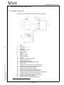

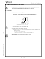
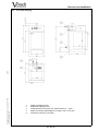
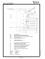
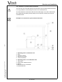
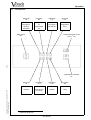
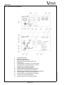

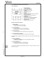
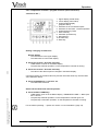


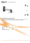

![[WAP035] [Evaluating Twittervane] Project Final Report](http://vs1.manualzilla.com/store/data/005882807_1-a2020170b6b6795bf72e9c3d683c54a5-150x150.png)