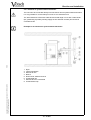
1
Operating Instructions Dryers for coating materials acc. to EN 1539 Operating Instructions for Dryers for coating materials LTU 60/60 (Serie 2000) P:\FM\LTU 60-60\Stammdatei_GB.fm 07/2002 LTU 60/60 Valid for: Maximum dissolvent concentration of <25 % of the lower explosion limit (LEL) Type Rated current Number of the unit Input power Year of construction Rating Rated voltage Connection diagram Nominal temperature Working space Minimum extracted-air flow rate Total vapour volume Highest temperature of the heating surface above 750 °C Maximum permissible quantity of dissolvent For other quantities of dissolvent please refer to the operating instructions! Read the Operating Instructions, observe them and keep them close to the device! Operating Instructions for Dryers for coating materials LTU 60/60 (Serie 2000) P:\FM\LTU 60-60\Stammdatei_GB.fm 07/2002 0 CONTENTS Section Title Page 0 Contents 3) 1 Important notice 5) 1.1 1.2 1.3 1.4 1.5 1.6 Use corresponding to its intended purpose Demands to the production manager Manual instructions Loading instructions Guarantee Special marks / indication of hazards 5) 6) 6) 6) 7) 8) 2 Description of the unit 9) 2.1 2.2 2.3 2.4 2.7 2.8 Description of the Items Structure Function Technical data Electrical equipment of the unit Mechanical equipment of the unit 9) 10) 11) 13) 21) 23) 3 Safety appliances 25) 3.2 3.4 3.5 Temperature limitation Door switch Other Safety Appliances 26) 27) 27) 4 Erection and installation 29) 4.1 4.2 4.3 4.4 4.5 4.6 4.7 Transport Erection Erection drawing Connection of the supply and exhaust air conduction Electrical Connection Disassembly Disposal 29) 30) 33) 35) 42) 43) 43) 5 Operation 45) 5.1 5.3 5.4 5.5 5.6 5.7 5.8 Working rules / Safety notes Reaction at interruptions Switchboard First commissioning Operation of the unit, standard equipment Operation of the unit, additional equipment Operation of the unit, special equipment 45) 46) 47) 49) 53) 57) 67) 3 of 88 Title Page 6 Error diagnosis 69) 6.1 6.2 Failure at restart Operating failures 69) 70) 7 Maintenance 73) 7.1 7.2 7.3 Testing and maintenance Repair Cleaning 73) 77) 81) 8 Connection diagram 83) 8.1 8.2 Spare parts list of the switch box Graphic Symbols 83) 84) 9 Spare parts list 85) 10 Documentation 87) Operating Instructions for Dryers for coating materials LTU 60/60 (Serie 2000) P:\FM\LTU 60-60\Stammdatei_GB.fm 07/2002 Section 4 of 88 Important notice 1 IMPORTANT NOTICE Read carefully and observe these operating instructions before erecting and commissioning the unit to avoid errors and the damages caused by them. Keep the operating instructions close to the unit. 1.1 Use corresponding to its intended purpose According to EN 1539 the dryer for coating materials with electrical heating series LTU is exclusively suitable for: Drying and hardening of liquid coating materials, containing combustible dissolvent which could form with air an explosive gas atmosphere. The maximum admissible quantities of dissolvent as of section 2.5 Quantities of Dissolvent are to be observed. Combustible materials of the explosion group II A and II B may be used here. A forbidden use which is not corresponding to its intended purpose is given at: Overloading the dryer with dissolvents, the coating system or changing the carrier material without recalculating the dissolvent values to be expected in the dryer Heating and storing of materials of the explosion group II C and explosive materials. Heating and storing of foodstuffs. 07/2002 Enabling the stay of living beings in the dryer and risking their life by that. Operating Instructions for Dryers for coating materials LTU 60/60 (Serie 2000) P:\FM\LTU 60-60\Stammdatei_GB.fm If you have doubts about special heat treatments please contact us. 5 of 88 Important notice 1.2 Demands to the production manager The unit must be operated only by instructed personnel. Based on these Operating Instructions the production manager has to prepare a corresponding instruction book. This instruction book has to consider the individual local and working conditions and the language of the operators. The production manager has to guarantee that all persons working on the unit (dryer) are familiar with the safety information and observe them. Work on electrical installations and components has to be carried out only by a skilled electrician. 1.3 Manual instructions The user has to prepare an instruction book for every dryer considering the operating instructions manual and the local working conditions which is easily understandable to the operating personnel and in their language. The instruction book has to contain particularly indications about which steps are to be taken when interruptions occur. - Loading instructions The user has to prepare an instruction about the maximum admissible load depending on the charging material for every dryer (loading instructions). Notes: The loading instructions have to indicate the maximum admissible quantity of dissolvent considering the size, the quantity and the coated surface of the parts to be dried for each case. → please observe section “2.5 Quantities of Dissolvent” (page 15) The solvent quantities may be also calculated again for establishing a loading instruction. → please observe section “2.6 Calculation of the solvent quantities” (page 17) The contractor has to make the instruction book and the loading instructions available to the operating personnel and has to secure its observance by e.g. regular training / instruction of the operators. 6 of 88 Operating Instructions for Dryers for coating materials LTU 60/60 (Serie 2000) P:\FM\LTU 60-60\Stammdatei_GB.fm 1.4 Dissolvents used, Maximum admissible dissolvent quantities for every working condition, Drying temperature (circulating air temperature), Hazards created by the materials or formulations used and the corresponding protection steps required, Steps to be taken at interruptions, Precautions to be taken when entering the dryer, Indications for maintenance. 07/2002 Notes: The instruction books include e.g. information about: Important notice 1.5 Guarantee The unit must not be changed in the version as it was supplied by us. A guarantee will only be granted if you act according to the directions of these Operating Instructions. The processes of development, production and shipping are according to the regulations of DIN ISO 9001. The safety and serviceability of the equipment is only guaranteed if the necessary checks and repair works are carried out either by expert skilled personnel or by our service people. Maintenance and cleaning may be carried out by customer’s specialised people. → please see section “7 Maintenance” (page 73) Only original spare parts are to be used at maintenance and repair work. The unit has been designed, manufactured and controlled before shipment according to the regulations of the EC. Certificate of Conformity / Manufacturer‘s Declaration: → please see section “10 Documentation” (page 87) Operating Instructions for Dryers for coating materials LTU 60/60 (Serie 2000) P:\FM\LTU 60-60\Stammdatei_GB.fm 07/2002 The unit corresponds to the following safety regulations: EC machine guideline 98/37/EG Low tension guideline 73/23/EWG Dryers and ovens safety requirements EN 746-1 Safety of machines EN 12100-1 (2003) EN 12100-2 (2003) Safety in electric-heating installations EN 60519-1 EN 60519-2 Electrical equipment of units EN 60204-1 Electromagnetic compatibility noise emission noise immunity Dryers and ovens, in which flammable substances are released - Safety requirements EN 61000-6-4 EN 61000-6-2 EN 1539 For the safety against explosions the erection and installation is very important as well as a correctly installed and duly functioning ventilation which is to be installed by the customer! 7 of 88 Important notice Special marks / indication of hazards ATTENTION / DANGER If these instructions are not observed this may lead to a hazard for the life of human beings and other living beings of the environment, or to damages of the unit or the loading material. ELECTRIC POWER It is used for drawing the attention to electric power. Access to this area is only allowed to skilled electricians. NOTE It is used to indicate a support. HOT SURFACE The air of the drying space and the parts getting in contact with the air of the drying space may be very hot. Wear protective clothing (protective gloves) INJURIES OF THE HANDS A general danger of injuries like cutting or contusion is indicated. Wear protective gloves! 07/2002 DANGER OF EXPLOSION An explosion may occur if the instructions are not observed. Abbreviations EN = Europäische Norm = European Standard EMV = Elektro-Magnetische-Verträglichkeit = Electromagnetic Compatibility UEG = Untere Explosionsgrenze = Lower Explosion Limit 8 of 88 Operating Instructions for Dryers for coating materials LTU 60/60 (Serie 2000) P:\FM\LTU 60-60\Stammdatei_GB.fm 1.6 Description of the unit 2 DESCRIPTION OF THE UNIT 2.1 Description of the Items Operating Instructions for Dryers for coating materials LTU 60/60 (Serie 2000) P:\FM\LTU 60-60\Stammdatei_GB.fm 07/2002 (Description of the standard unit without additional equipment) 1 2 3 4 5 6 7 8 9 10 11 12 13 14 15 1.) Door Door lock Door switch Switch box Temperature sensor (without representation) Bracket 1.) (without representation) Insert 1.) (without representation) Supply air fitting Exhaust air fitting Motor with fan impeller (circulating air) Heater Exhaust air fan Flow indicator (exhaust air, circulating air) Safety-Temperature Limiter (STL) (without representation) Floor sheet (without representation) additional equipment 9 of 88 Description of the unit Structure Thermal insulation: The drying chamber for coating materials is a double-wall construction of steel metal sheet and heat insulated with mineral fibre (80 mm). Circulating air: A good distribution of temperature and flow in the working space of the unit is given by a high flow rate of circulating air. A hot gas ventilator is installed under the floor of the working space. Heating: The electrical heating is done by tubular heating element of stainless steel (material 1.4828). Temperature regulation: The temperature of the working space is controlled by an electronic temperature regulating system with semiconductor switching elements. Vertical air guiding: The air entry is at the top side of the working space and the air extraction is at the bottom of the working space. Horizontal air guiding: 1.) The air entry is at the rear side of the interior space with an air stream to the front side. The air extraction is at the bottom of the working space. Safety against explosions: The safety against explosions in the working space is achieved by a technical ventilation and by the limitation of the quantity of dissolvent. 07/2002 Interior housing: The housing is welded tight to avoid the penetration of dissolvent fumes into the thermal insulation. Minimum extracted-air flow rate: The air in the working space is exchanged continuously. (100% flow of exhaust air during the main evaporation time). Reduced extracted-air flow rate: The reduced extracted-air flow rate is at least 25 % of the minimum extracted-air flow rate when the exhaust air fan is disconnected. Control of the circulating- / extracted-air: The circulating- / extracted-air flow rate is controlled by flow indicators which are separated and operating independently from each other. Pick-up of material: Notched rails mounted at the side for the pick-up of angular supports. Different kinds of inserts (wire-mesh shelves, gratings, loading trays, etc.) may be placed on the angular supports. The floor of the working space is not to be loaded. Total load of the notched rails: → please observe section “2.4 Technical data” (page 13) 1.) additional equipment 10 of 88 Operating Instructions for Dryers for coating materials LTU 60/60 (Serie 2000) P:\FM\LTU 60-60\Stammdatei_GB.fm 2.2 Description of the unit 2.3 Function The drying chamber for coating materials series LTU is designed and constructed according to EN 1539. When the dryer is loaded with feeding material the and the doors are closed, the feeding material in the working space is enclosed in a turbulent stream of circulating air. The turbulent circulation takes care of a good and equally distributed heat transfer to the drying goods. A defined quantity of exhaust air (= minimum extracted-air flow rate) is extracted continuously from the circulating air flow by an additional exhaust air fan. A corresponding volume of supply air is aspirated by the developing vacuum and mixed with the circulating air. This air exchange is important for the safety! By the air volume fed the mixture of dissolvent vapour / air created in the dryer is kept under the lower explosion limit. → please observe section “5.2 Main evaporation time” (page 46) The circulating air flow rate and minimum extracted-air flow rate are controlled by flow switches operating independently from each other (differential pressure flow switches). The volume flow mixed with supply air and circulating air is aspirated passing the electrical heater and fed to the working space by the circulating air fan. When the doors of the dryer are open, the heating and the circulating air fan are disconnected for the protection of the operating personnel. 07/2002 The circulating air are connected automatically when the doors are closed. The heating has to be connected manually by the operator after checking the drying temperature set at the pertaining operating and loading instructions. When restarting (main switch on) the heating can be connected only after a safety scavenging time (5-times air exchange in the complete vapour space at the minimum extracted-air flow rate) at closed unit door. Operating Instructions for Dryers for coating materials LTU 60/60 (Serie 2000) P:\FM\LTU 60-60\Stammdatei_GB.fm Minimum extracted-air flow rate is according to the flow rate laid out for the maximum dissolvent quantity which may be brought into the dryer for each batch. Evaporation mean time is according to the time where the main quantity of dissolvent is evaporating and carried off → please observe section “5.2 Main evaporation time” (page 46) 11 of 88 Description of the unit 2.3.1 Air guiding Conversion to horizontal air guiding 1.) - Loosen the screws at the rear wall of the interior housing. Remove the unperforated rear wall sheet of the vertical air guide. Insert the perforated rear wall sheet of the horizontal air guide and fasten the screws. The conversion from horizontal air guiding to vertical air guiding is done in reverse order. Horizontal air guiding 1.) 07/2002 Vertical air guiding 1.) Operating Instructions for Dryers for coating materials LTU 60/60 (Serie 2000) P:\FM\LTU 60-60\Stammdatei_GB.fm The use of loading trays is only possible at horizontal air guiding. additional equipment 12 of 88 Description of the unit 2.4 Technical data 60/60 Interior space (working space) Interior dimensions Width Height Depth Operating Instructions for Dryers for coating materials LTU 60/60 (Serie 2000) P:\FM\LTU 60-60\Stammdatei_GB.fm 07/2002 Exterior dimensions Width total Height Depth 0.216 mm 600 600 600 mm 796 1700 850 Loading / carrying capacity Interior housing total reinforced 1.) kg 150 300 Floor kg ----- surface load reinforced 1.) Wire-mesh shelves 1.) quantity concentrated load surface load max. kg Gratings 1.) kg 50 200 Weight (net) kg 275 Minimum extracted-air flow rate Reduced extracted-air flow rate m3/h 90 22.5 sec. 90 Circulating air flow rate standard reinforced 1.) m3/h 16 33 Total vapour volume m3 concentrated load surface load Scavenging time (5-times air exchange) 1.) m3 additional equipment 13 of 88 12 10 20 0.414 Description of the unit 60/60 Sound pressure level (acc. to DIN 45635) dB(A) < 70 Disconnecting temperature Safety-Temperature Limiter (STL) Temperature limit cut-out (TLC) °C 300 200 Temperature-Safety Class (acc. to EN 60519-2) Safety-Temperature Limiter (STL) Temperature limit cut-out (TLC) Nominal temperature 1 2 °C Electrical data Rated voltage / frequency 200 for differing data please see nameplate V / c/s 400, 3/(N)PE, AC 50/60 A kW kW 11.0 6.0 7.0 Reinforced heating power 1.) Rated current Rated power Input power A kW kW 22.0 12.0 13.0 1.) Operating Instructions for Dryers for coating materials LTU 60/60 (Serie 2000) P:\FM\LTU 60-60\Stammdatei_GB.fm 07/2002 Rated current Rated power Input power additional equipment 14 of 88 Description of the unit 2.5 Quantities of Dissolvent These values are valid for a surface coating containing a dissolvent at 40 g/m³ and 20°C with a max. concentration of < 25 % of the lower explosion limit (LEL). (calculated according to EN 1539) The maximum permissible quantity of dissolvent [g] is the quantity which is allowed to be fed in the dryer for each batch at the corresponding minimum extracted-air flow rate and at the corresponding drying temperature [°C]. For drying of mould varnish the dissolvent quantity may be raised to a value of 10 times of the standard. For drying of impregnating resin the dissolvent quantity may be raised to a value of 20 times of the standard. LTU 60/60 [ g ] 55 50 45 40 35 30 25 20 15 5 Operating Instructions for Dryers for coating materials LTU 60/60 (Serie 2000) P:\FM\LTU 60-60\Stammdatei_GB.fm [ °C ] 15 of 88 200 190 180 170 160 150 140 130 120 110 100 90 80 70 0 60 07/2002 10 Operating Instructions for Dryers for coating materials LTU 60/60 (Serie 2000) P:\FM\LTU 60-60\Stammdatei_GB.fm 07/2002 Description of the unit 16 of 88 Description of the unit 2.6 Calculation of the solvent quantities The solvent quantities for chamber dryers must be calculated again when the operating conditions are deviating or changing. Drying of mould varnish If the chamber dryers are used for the drying of mould varnish the data for the maximum allowable quantities of inflammable materials may be increased by up to 10 times. Drying of impregnating resin If the chamber dryers are used for the drying of impregnating resin the data for the maximum allowable quantities of inflammable materials (solvent quantities) may be increased by up to 20 times for the surface drying. Main evaporation time The main evaporation time after loading the heated chamber dryer is at least - 5 minutes when drying surface coated material, - 15 minutes when drying mould varnish, - 60 minutes when drying impregnating resin, However when the dryer is loaded before heating it up the main evaporation time is equal to the time until the drying temperature is reached. When drying mould varnish the main evaporation time is equal to the time until the drying temperature is reached plus 5 minutes at least. When drying impregnating resin the main evaporation time is equal to the time until the drying temperature is reached plus 30 minutes. Operating Instructions for Dryers for coating materials LTU 60/60 (Serie 2000) P:\FM\LTU 60-60\Stammdatei_GB.fm 07/2002 A shorter main evaporation time can only be accepted when the corresponding safety is proven. Predrying losses The predrying loss may be estimated as follows for surface coated parts: After an average predrying time of 10 minutes - 25 % 20 minutes - 45 % 30 minutes - 50 % of the applicated quantity of inflammable materials (solvents). The predrying loss may be estimated as follows for mould varnish drying: After an average predrying time of 10 minutes - 15 % 20 minutes - 25 % 30 minutes - 35 % 40 minutes - 40 % 50 minutes - 45 % 60 minutes - 50 % of the applicated quantity of inflammable materials (solvents). The average predrying time for chamber dryers is half of the time which is needed for coating the goods of one charge plus an eventual waiting time after coating until they are loaded into the dryer. 17 of 88 Description of the unit Calculation of the maximum admissible solvent / varnish quantities for a chamber dryer: For the calculation of the maximum admissible solvent / varnish quantity the lower explosion limit (LEL) of the solvent in [g/m³] is required. If the lower explosion limit (LEL) of the solvent is indicated in [Vol%], the molar mass Mmol in [g/mol] is also required for the conversion to [g/m³] (LEL). g M mol ---------mol g - × LEL [ Vol% ] LEL ------3- = --------------------------------------------3 m m 0, 024 ---------- × 100 mol If the lower explosion limit and the molar mass of the solvent are unknown, LEL = 40 g/m³ is used. CLELadm < 25 % LEL C LELadm × LEL C adm = ---------------------------------------100% The evaporation time at the drying temperature used is: 2, 58 t o = -----------ϑ The time for an air exchange in the complete vapour space of the dryer is: V t w = --------------Q minϑ If the volume of the loaded goods is more than 10 % of the useful space it has to be subtracted from the total vapour space when calculating the maximum admissible solvent quantity. 07/2002 The relation of the evaporation time to the time for one air exchange in the dryer is: t ----otw The value of γ at tO / tw has to be taken from the diagram and used in the calculation of the solvent quantity to be applied: The total quantity of solvent to be applied is: A predrying loss of 45 % is estimated at a predrying time of e.g. 20 minutes. Thus the content of solvent in the coating before predrying corresponds to a value which is by 55 % higher than the value of the solvents contained in the applied varnish. M max × 100% M predry = -------------------------------------( 100% ∠ 45% ) If the content of solvents in the varnish applied is e.g. 60 %, the total weight of the varnish in one charge is: M predry × 100% M varn = ---------------------------------------60% 18 of 88 Operating Instructions for Dryers for coating materials LTU 60/60 (Serie 2000) P:\FM\LTU 60-60\Stammdatei_GB.fm C adm × 293 × V M max = -------------------------------------( 273 + ϑ ) × γ Operating Instructions for Dryers for coating materials LTU 60/60 (Serie 2000) P:\FM\LTU 60-60\Stammdatei_GB.fm 07/2002 Description of the unit The dependence γ of tO / tw has to be taken from the diagram: 19 of 88 Description of the unit Calculation sample of the maximum admissible quantity of solvent / varnish for a chamber dryer: LTU 60/60 Total vapour volume Drying temperature Minimum extracted-airflow rate LEL max. concentration Content of solvent of the varnish Predrying time / air C adm C LELadm × LEL = ---------------------------------------100% V LTU _ _ / _ _ 0.414 m³ 190 °C 102 m³/h ϑ Qminϑ _ _ _ _ m³ _ _ _ _ °C _ _ _ _ m³/h CLEL 40 g/m³ CLELadm < 25 % 60 % _ _ _ _ g/m³ ____% ____% t _ _ _ _ minutes 20 minutes g 25% × 40 ------3m gC adm ------------------------------------ = 10 --------3 100% m( s ) C adm g … × … ------3g m = ------------------------------- = … ------3100% m (s) Evaporation time at drying temperature 2, 58 t o = -----------ϑ Air exchange in the vapour volume 2, 58 t o = ---------------- = 0, 0136h 190°C 3 2, 58 t o = ------------- = …h …°C 3 0, 414m - = 0, 00406h t w = ---------------------3 m 102 ------h …m t w = -------------3 = …h m … ------h t ----otw t 0, 0136h----o- = ----------------------= 3, 398 tw 0, 00406h t …h----o- = -------= … tw …h The value for γ at to / tw has to be taken from the diagram: γ = 0, 16 γ = … V t w = --------------Q minϑ M max C adm × 293 × V = -------------------------------------( 273 + ϑ ) × γ M max 3 3 g g 10 -----------× 293 × 0, 414m … -----------× 293 × …m 3 3 m (s) m (s) = ---------------------------------------------------------------------- = 16, 37g M max = ------------------------------------------------------------ = …g ( 273 + 190 ) × 0, 16 ( 273 + … ) × … Predrying loss at 20 minutes M max × 100% M predry = -------------------------------------( 100% ∠ 45% ) 16,37g × 100% M predry = -------------------------------------- = 29, 76g ( 100% ∠ 45% ) …g × 100% M predry = -------------------------------------- = …g ( 100% ∠ …% ) Weight of varnish at 60 % content of solvent M predry × 100% M varn = ---------------------------------------60% 29, 76g × 100% M varn = --------------------------------------- = 49, 6g 60% 20 of 88 …g × 100% M varn = ------------------------------ = …g …% Operating Instructions for Dryers for coating materials LTU 60/60 (Serie 2000) P:\FM\LTU 60-60\Stammdatei_GB.fm Max. quantity of solvent to be applied 07/2002 Relation of Description of the unit 2.7 Electrical equipment of the unit 2.7.1 Temperature controller Jumo dTRON 04.1 2.) 2.7.2 Temperature controller 1.) 2.) Jumo dTRON 04.1 with precontact, for gating of a time-lag relay for treatment time with disconnecting of the heating. 2.7.3 Clock relay 1.) Gating of a clock relay for treatment time with disconnecting of the heating by a precontact of the temperature controller. Omron 2.7.4 Temperature controller 1.) 2.) Eurotherm 2204 CC (nominal value ramp) Eurotherm 2404 CP (1 program, 8 steps) Eurotherm 2404 P4 (4 programs, je 8 steps each) Jumo Dicon 1001 (25 programs, integral time switch) 2.7.5 External operation of the program controller 1.) Separated key for the start of a program as simplified operating of the program controller. 07/2002 2.7.6 Safety - temperature limiter (STL) Unit protection 2.7.7 Temperature limit cut-out (TLC) Jumo iTRON Operating Instructions for Dryers for coating materials LTU 60/60 (Serie 2000) P:\FM\LTU 60-60\Stammdatei_GB.fm 2.7.8 Door switch Disconnecting of the heating and the circulating air fan when the door is opened. 2.7.9 Flow indicator (differential pressure switch) The circulating-air and extracted-air flow rates are monitored each by a differential pressure switch. 2.7.10Reinforced heating power 1.) The heating is equipped with 12 radiators. 2.7.11Reinforced circulating air fan 1.) Motor of the circulating air fan with double speed. 1.) 2.) additional equipment documentation of the equipment in section 10 Documentation. 21 of 88 Description of the unit 2.7.12Monitoring unit 1.) Monitoring of the main evaporation time independent of the program controller. Automatic switching to reduced exhaust airstream after finishing the main evaporation phase. 2.7.13Exhaust air fan The air in the working space / evaporation room is exchanged continuously when the exhaust air fan is running. (minimum extracted-air flow rate during the main evaporation time) The air exchange is reduced to 25 % of the minimum extracted-air flow rate when the exhaust air fan is disconnected. 2.7.14Recorder 1.) 2.) 1-channel- strip chart line recorder Jumo Logoline 500 d with fixed resistance thermometer Pt 100 beside the controller sensor. 2.7.15Preparation of the recorder 1.) with fixed resistance thermometer Pt 100 mounted beside the controller sensor and guided on clamps. 2.7.16Time switch 1.) 2.7.17Operating hour meter 1.) 07/2002 Day-program-clock 24 h Week-program-clock 168 h Automatic connection of the unit with switching in of the heating. Disconnection of the unit. Grässlin MIL 72 1.) 2.) additional equipment documentation of the equipment in section 10 Documentation. 22 of 88 Operating Instructions for Dryers for coating materials LTU 60/60 (Serie 2000) P:\FM\LTU 60-60\Stammdatei_GB.fm 2.7.18All-round light 1.) Additional error message or end-of-process message. Description of the unit 2.8 Mechanical equipment of the unit 2.8.1 Pick-up of material type 60/60 Notched rails Mounted at the side for the pick-up of angular supports. Total load of the notched rails → please observe section “2.4 Technical data” (page 13) Floor of the working space Not to be loaded 2.8.2 Angular support 1.) For the pick-up of inserts. 2.8.3 Inserts 1.) Wire-mesh shelves Load of the wire-mesh shelves → please observe section “2.4 Technical data” (page 13) Gratings Load of the gratings → please observe section “2.4 Technical data” (page 13) Loading trays 1/1 size 1/2 size 07/2002 Telescopic rails for pulling out the inserts. Operating Instructions for Dryers for coating materials LTU 60/60 (Serie 2000) P:\FM\LTU 60-60\Stammdatei_GB.fm 2.8.4 Door seal Silicone Glass fibre 1.) 1.) additional equipment 23 of 88 Description of the unit 2.8.5 Lead-through 1.) Diameter 25 or 40 mm in the left or in the right side wall. 2.8.6 Filter 1.) Fresh air filter class F 5 acc. to EN 779 (only in connection with exhaust air fan) 2.8.7 Kit for fastening the floor anchorage 1.) Securing device against tilting of the unit with retractable inserts on telescopic rails. 1.) Operating Instructions for Dryers for coating materials LTU 60/60 (Serie 2000) P:\FM\LTU 60-60\Stammdatei_GB.fm 07/2002 2.8.8 Horizontal air guiding 1.) Conversion kit for changing the air guiding from vertical to horizontal. additional equipment 24 of 88 Safety appliances 3 SAFETY APPLIANCES Do not make any manipulation at the safety appliances! Every unauthorised intervention may have unforeseeable consequences. Danger of explosion! The function of the safety appliances has to be checked regularly. → please observe section “7.1 Testing and maintenance” (page 73) 3.1 Control of the circulating - and exhaust air flow rate Flow switch The control of the air flow rates which are necessary for a safe operation during the different phases of operation is done by each a flow switch (differential pressure switch). The heating is released only when the unit runs correctly. If the minimum air flow rate is under its minimum value and the circulating air flow fails the corresponding flow switch disconnects the heating permanently and at all poles. At the operating phase with reduced extracted-air flow the unit is switched additionally to minimum extracted-air flow rate. Indication of the error by optical and acoustic signal. The acoustic signal is surpressed when the door of the dryer is open. The rest position of the flow indicators for circulating air and exhaust air is checked after every switching on the main switch. The rest position of the flow indicators for circulating air is checked after every closing of the unit door with the main switch connected. Operating Instructions for Dryers for coating materials LTU 60/60 (Serie 2000) P:\FM\LTU 60-60\Stammdatei_GB.fm 07/2002 Rest position monitoring The motors of the ventilators will start only when the flow indicators are working correctly and when they are in the rest position. 25 of 88 Safety appliances Temperature limitation Safety temperature limiter (STL) Thermal protection as device protection (fire protection set firmly at factory, intrinsically break-proof temperature limiter (thermal safety class 1 acc. to EN 60519-2). The STL is independent from the control equipment electrically and in its function. If the set temperature is exceeded the STL disconnects the heating permanently and at all poles. Indication of the error by optical and acoustic signal. Disconnecting temperature: → please observe section “2.4 Technical data” (page 13) Notice for first commissioning temperature limiter (STL) The Temperature limiter may trigger during the transport or at temperatures under 0°C. Consequence at first commissioning: Unit is connected: - Red indicator light ”error heating” is illuminated. Press the push button under the screw cap of the STL (at an ambient temperature of at least 20 °C) firmly with the aid of an approoirate tool. - Red indicator light ”error heating” goes out. Temperature limit cut-out (TLC) Unit protection and material protection (thermal safety class 2 acc. to EN 60519-2). If the set temperature is exceeded the TLC disconnects the heating permanently and at all poles. Indication of the error by optical and acoustic signal. Disconnecting temperature: → please observe section “2.4 Technical data” (page 13) 07/2002 At the operating phase with reduced extracted-air flow the unit is switched additionally to minimum extracted-air flow rate. Operating Instructions for Dryers for coating materials LTU 60/60 (Serie 2000) P:\FM\LTU 60-60\Stammdatei_GB.fm 3.2 26 of 88 Safety appliances 3.3 Control Unit 1.) For the control of the main evaporation time independent of the program controller and for the automatic switching to reduced exhaust air operation. Safety circuit: In the case of a faulty programming or in case of an error in the program controller. Keep to the main evaporation time set related to the set drying temperature and automatic switching from minimum extracted-air flow rate (fresh air ) to reduced extracted-air flow rate (circulating air) only after the controlled main evaporation time has passed. 3.4 Door switch When the door is opened the heating and the circulating air fan are disconnected and the exhaust air fan is connected by the door switch. When the door is closed the circulating air fan is connected again by the door switch. After checking the drying temperature set the heating has to be connected manually pressing a key according to the corresponding Operating- / Loading Instructions. 3.5 Other Safety Appliances Main switch Main switch lockable by a padlock. 07/2002 Protective motor switch Overload and short circuit protection of the ventilator motors and the control voltage by protective motor switches. Operating Instructions for Dryers for coating materials LTU 60/60 (Serie 2000) P:\FM\LTU 60-60\Stammdatei_GB.fm Floor anchoring 1.) When the unit is equipped with retractable inserts on telescopic rails it is necessary to anchor the unit at the rear side on the floor to avoid a tilting of the unit to the front side due to the weight of the inserts pulled out. 1.) additional equipment 27 of 88 Operating Instructions for Dryers for coating materials LTU 60/60 (Serie 2000) P:\FM\LTU 60-60\Stammdatei_GB.fm 07/2002 Safety appliances 28 of 88 Erection and installation 4 ERECTION AND INSTALLATION Qualified personnel is required for the transport, erection and installation of the unit! The corresponding accident prevention rules have to be observed. 4.1 Transport Shipment is done on a transport pallet. Transport the unit to the erecting place with a fork lift or suitable lift truck. Dead weight → please observe section “2.4 Technical data” (page 13) 07/2002 Do not use belts for lifting or erecting the unit! Unit without transport eyes Lift the unit carefully at the bottom from the pallet with a fork lift or suitable lift truck. - Remove the pallet. - Erect the unit at the erecting place → please observe section “4.3 Erection drawing” (page 33) Operating Instructions for Dryers for coating materials LTU 60/60 (Serie 2000) P:\FM\LTU 60-60\Stammdatei_GB.fm We recommend: keep the pallet parts for service or move. 29 of 88 Erection and installation Erection The installation room or area has to be marked as fire endangered. Please note: When erecting this unit the area / room has to be characterised as exposed to the danger of fire and has to be equipped with the corresponding installations. It is not allowed to install and operate the unit in hazardous areas or rooms. Requirements at erecting: Standard foundation Non-flammable in a periphery of at least 2.5 m Flush and horizontal Free of vibrations Electrically conductive (against electrostatic charging) 07/2002 Observe the loading capacity of the floor Weight of the unit in addition to the weight of the charge. → please observe section “2.4 Technical data” (page 13) Operating Instructions for Dryers for coating materials LTU 60/60 (Serie 2000) P:\FM\LTU 60-60\Stammdatei_GB.fm 4.2 30 of 88 Erection and installation Erecting room Temperature max. 40 °C Dry max. 70 % relative humidity Free of draught Sufficiently aerated Distance from rear side / roof → please observe section “4.3 Erection drawing” (page 33) Supply- and exhaust air conductions → please observe section “4.4 Connection of the supply and exhaust air conduction” (page 35) Install the unit horizontally Operating Instructions for Dryers for coating materials LTU 60/60 (Serie 2000) P:\FM\LTU 60-60\Stammdatei_GB.fm 07/2002 Keep the distances indicated in the erection drawing to avoid fire and local overheating of the unit or its surroundings and to guarantee a troublefree operation of it. → please observe section “4.3 Erection drawing” (page 33) 31 of 88 Operating Instructions for Dryers for coating materials LTU 60/60 (Serie 2000) P:\FM\LTU 60-60\Stammdatei_GB.fm 07/2002 Erection and installation 32 of 88 Erection and installation 4.3 Erection drawing Operating Instructions for Dryers for coating materials LTU 60/60 (Serie 2000) P:\FM\LTU 60-60\Stammdatei_GB.fm 07/2002 (Presentation standard unit LTU 60/60 without additional equipment) 1 Exhaust air DN 100 2 Supply air DN 100 33 of 88 Erection and installation 4.3.1 Mounting of the exhaust air fan Assembly of the exhaust air fan and connecting collar when the unit is shipped with disassembled exhaust air fan: 07/2002 1. Fasten the bracket (3) at the rear wall of the unit. 2. Insert the aspiration side of the exhaust air fan (4) in the exhaust air collar (2) in the rear wall of the unit and fasten it with the hex bolts (5)on the bracket. 3. Insert the socket (6) on the exhaust air fan (4) and the pipe bend (1) in the socket (6). Secure the pipe pieces with sheet metal drive screws. 4. Connect the flexible tubes (8) with the connecting collar and observe the polarity (+ and -) 5. Install the flexible tubes (8) in such a way that they are protected against a heating up by the pipe bend (1) or the exhaust air fan (4). Make the electrical connection. 1. Guide the end of the cable through the screw joint and fasten the screw joint. 2. Fasten the cable lugs to the indicated terminals. blue U1 brown V1 black W1 green/yellow PE Operating Instructions for Dryers for coating materials LTU 60/60 (Serie 2000) P:\FM\LTU 60-60\Stammdatei_GB.fm Colour of the cable Terminal 34 of 88 Erection and installation 4.4 Connection of the supply and exhaust air conduction The connection of the supply and exhaust air conduction’s has to be done only by qualified persons. The total length of the directly connected supply and exhaust air conduction’s (NB 100) should not exceed 5 m with max. 3 tube bends (90°) (R > D) An additional extension of the conduction’s reduces the extracted-air flow rate Supply and exhaust air conduction’s have to be installed separated from each other. 4.4.1 Supply air systems The supply air has to be taken from a neutral area which is free of dissolvent vapours. Special consideration has to be given to the effects of coated material which is stored in the installation zone of the dryer for predrying. If it is not possible to take the supply air at the installation area, the unit has to be connected to the customer’s supply air system. The connection has to be tight (NB 100). The connection at the unit’s side must not be loaded mechanically. The lowest operating temperature of the unit depends on the temperature of the supply air fed. (Lowest operating temperature = supply air temperature + 20 ... 30 K) Operating Instructions for Dryers for coating materials LTU 60/60 (Serie 2000) P:\FM\LTU 60-60\Stammdatei_GB.fm 07/2002 The supply air fed may guided through a fresh air filter and thus cleaned of particles. (Filter of the class F5 are part of the optional standard accessories.) 35 of 88 Erection and installation 4.4.2 Exhaust air systems Due to the possibly existing vapours and the thermal load the exhaust air should not be guided into the installation area , we recommend the connection to customer’s exhaust air system. If the unit is operated without an exhaust air conduction the necessary distances to the wall and roof have to be considered. Danger of fire! → please observe section “4.3 Erection drawing” (page 33) For the discharge of the exhaust air released during the drying and thermal treatment the following has to be considered: No possible ignition sources in the in the exhaust air conduction. Observation of the valid corresponding national regulations related to the emission values. If necessary use exhaust air treatment processes as e.g. thermal or catalytic postcombustion installations (TNV, KNV, etc.). The pipes of the exhaust air system have to be of incombustible material (e.g. metal). They have to be installed in a way that no fire hazard could emerge from the developing temperature. Surface temperatures (Tsurface = operating temperature < nominal temperature) A measuring orifice (d = 40mm) has to be installed in the exhaust air conduction at a suitable or accessible place (in a straight tube section, about 1m behind the exhaust air collar). This measuring orifice is necessary for the control of the extracted-air flow rate during the maintenance, checking and service work. 07/2002 A sufficient thermal insulation has to be provided. (e.g. pipe casing of mineral fibre) At the conduction installation care has to be taken that it is not possible that deposits build up and that an easy cleaning of the exhaust air line is possible. (Revision orifices, possibility to dismantle sections, etc.) The exhaust air of the unit must not be brought together with fuel-gas. It is only allowed to guide the exhaust air into chimneys if these do not have a connection with fire places or other workshops. The exhaust air can only be guided into ventilation shafts if these have a fire-resistant separation to other workshops. 36 of 88 Operating Instructions for Dryers for coating materials LTU 60/60 (Serie 2000) P:\FM\LTU 60-60\Stammdatei_GB.fm By the installation of the pipes for exhaust air it has to be granted that eventually existing condensate will not run back to the unit. (Install the exhaust air conduction if possible with approximately 2% falling gradient from the unit and drain the condensate specifically into e.g. a condensate trap). Erection and installation 4.4.3 Exhaust air systems without extraction The unit has to be connected directly to an exhaust air line at systems without extraction. It is only possible to connect always one unit to one exhaust air line. The total resistance to flow with a NB 100 and a total length of 5 m with 3 tube bends (90°) (deducting a possibly existing supply air line and fresh air filter) should not be exceeded at this. 07/2002 Example for an exhaust air system without extraction: Dryer Thermal insulation Exhaust air line Branch Roof bonnet, deflector bonnet Condensate line Shutoff valve for condensate Condensation trap Operating Instructions for Dryers for coating materials LTU 60/60 (Serie 2000) P:\FM\LTU 60-60\Stammdatei_GB.fm 1 2 3 4 5 6 7 8 37 of 88 Erection and installation 4.4.4 Exhaust air systems with extraction The extracting fan of the exhaust air system has to be suitable for temperatures of the conveying means occurring. For the connection of the device to an exhaust air system with a central extraction a flue interrupter has to be provided in any case. A flue interrupter may constructed for example of components of the ventilation techniques usual in the trade. Operating Instructions for Dryers for coating materials LTU 60/60 (Serie 2000) P:\FM\LTU 60-60\Stammdatei_GB.fm 07/2002 Examples for flue interrupters: 38 of 88 Erection and installation Dimensioning of the required extracted-air flow rate at the flue interrupter: The extracted-air flow rate at the flue interrupter should be dimensioned as follows: Quantities of exhaust air: → please observe section “2.4 Technical data” (page 13) LTU 60/60 LTU _ _/_ _ Extracted-air flow rate Vext 102 m³/h Vext Diameter of the exhaust air collar Dexh 100 mm Dexh _ _ _ m³/h mm Area of the exhaust air collar D exh D exh A exh = ----------- × ----------- × π 2 2 Aexh Diameter of the flue interrupters Dflue 0.00785 m² 150 mm Aexh _ _ _ m² Dflue _ _ _ mm Aflue _ _ _ m² Area of the flue interrupter D flue D flue A flue = ------------ × ------------ × π 2 2 Aflue Amplification factor in the flue interrupters v 1.15 v 1.15 Vflue 264 m³/h Vflue _ _ _ m³/h 0.01767 m² Flow rate of the exhaust air fan The length of the exhaust air system and its design (e.g. nominal cross section, number of tube bends, etc.) have at this no influence on the devices. Operating Instructions for Dryers for coating materials LTU 60/60 (Serie 2000) P:\FM\LTU 60-60\Stammdatei_GB.fm 07/2002 V ext × A flue × v V flue = -------------------------------------A exh 39 of 88 Operating Instructions for Dryers for coating materials LTU 60/60 (Serie 2000) P:\FM\LTU 60-60\Stammdatei_GB.fm 07/2002 Erection and installation Examples of exhaust air systems with a central extraction (schematic): 40 of 88 Erection and installation 4.4.5 Connection of several units to an exhaust air system with extraction If several units are connected to a common exhaust air system with central extraction they have to be locked against each other in the terms of ventilation techniques and the performance of the extracting fan has possibly to be adapted. Operating Instructions for Dryers for coating materials LTU 60/60 (Serie 2000) P:\FM\LTU 60-60\Stammdatei_GB.fm 07/2002 Example of several devices on one exhaust air system: 1 2 3 4 5 6 7 8 9 10 11 Dryer Flue interrupter Flow switch Shut-off slide Butterfly damper Collecting line for flue gas Central extracting fan Disposal of exhaust air Condensate line Shut-off valve for condensate Condensate trap 41 of 88 Erection and installation Electrical Connection The electrical connection must be done only by skilled electricians. Observe the corresponding national regulations for the electrical connection. The network conditions have to be in accordance with the data on the nameplate. Variations of the mains voltage max. ± 10 %. Observe the VDE- and technical connection regulations of the local electricity supply company (EVU). Connection to power supply with clockwise rotating field. Information about mains connection and necessary fuse protection on the connection diagram. We recommend the connection through a leakage current contactor. (300 mA) The mains connection is in the switch box at the main switch. The mains connection terminals have to be equipped with a cover. Sense of rotation of the motor: Check the sense of rotation of the fan: Watch the rotation indicating arrow. Remove the bottom sheet metal in the working space: - Bottom sheet: → please see section “2.1 Description of the Items” (page 9) - Connect and disconnect shortly the main switch. - The sense of rotation is clockwise if you look from above on the impeller. 07/2002 Since the sense of rotation of the circulating air fan cannot be seen directly it may be determined as follows: Attention! Danger of injuring: Do not touch the running impeller! Operating Instructions for Dryers for coating materials LTU 60/60 (Serie 2000) P:\FM\LTU 60-60\Stammdatei_GB.fm 4.5 42 of 88 Erection and installation 4.6 Disassembly Disassembly of the dryer for a change of location. Separation of the electrical connection has to be done only by skilled electricians. Transport of the dryer → please observe section “4.1 Transport” (page 29) One door has to be removed for safety reasons, to avoid the danger of locking up oneself or somebody. 4.7 Disposal Disassembly of the unit for disposal. Separation of the electrical connection has to be done only by skilled electricians. Transport of the dryer → please observe section “4.1 Transport” (page 29) Special waste There are some electrical and electronic components in the unit which have to be disposed of as special waste if necessary. 07/2002 If desired we take care of a disposal without endangering the environment. Disposal by the user If the user disposes of the unit the following has to be carried out: - The door lock has to be destroyed or one door has to be removed for safety reasons, to avoid the danger of locking up oneself or somebody. - Carry the special waste to the corresponding appropriate disposal place. Operating Instructions for Dryers for coating materials LTU 60/60 (Serie 2000) P:\FM\LTU 60-60\Stammdatei_GB.fm The nationally and locally applicable regulations for the disposal valid at the time the disposal have to be observed for the other materials and the special waste. 43 of 88 Operating Instructions for Dryers for coating materials LTU 60/60 (Serie 2000) P:\FM\LTU 60-60\Stammdatei_GB.fm 07/2002 Erection and installation 44 of 88 Operation 5 OPERATION The following regulations and safety notes have to be observed for the operation. 5.1 Working rules / Safety notes The unit has to be used exclusively for applications as described in section 1.1 Use corresponding to its intended purpose (page 5)! Do not make any manipulation at the safety appliances! Every unauthorised intervention may have unforeseeable consequences. Explosion hazard! The control and operation of the dryer is only permitted to instructed operators and only according to customer’s ”Manual instructions”. → please observe section “1.3 Manual instructions” (page 6) The loading of the dryer is only allowed according to the ”Loading instructions” of the customer. → please observe section “1.4 Loading instructions” (page 6) The quantities of dissolvent indicated in section 2.5 are to be observed for the maximum admissible quantity of dissolvent. For other operating conditions or under consideration of the pre-drying losses the dissolvent quantities have to be calculated anew according to EN 1539. (please observe section 2.6 calculation of the dissolvent quantities) 07/2002 If the volume of the loaded material is more than 10 % of the working space, it has to be deducted from the total vapour volume when calculating the maximum admissible quantity of dissolvent. The loading of the dryer has to be done only if the technical ventilation is active. Never operate with lacquers made basically of epoxy resin and nitro-cellulose at the same time. (Hazard of spontaneous ignition) When working with nitro-cellulose lacquers set the temperature controller and the temperature limit cut-out in such a way that the temperature on the material to be dried is not higher than 130 °C. Operating Instructions for Dryers for coating materials LTU 60/60 (Serie 2000) P:\FM\LTU 60-60\Stammdatei_GB.fm When loading the dryer leave 25 % of the flow cross section free. The maximum workplace concentration (MAK-values) have to be observed and a sufficient air exchange in the installation room has to be taken care for. Keep the working space and equipment, exhaust air line, etc. clean. Remove thoroughly loading residues. Fire hazard! Keep the dryer free of combustible objects and materials and also don‘t leave these on the dryer. The floor of the working space is not to be loaded. Total load of the notched rails: → please observe section “2.4 Technical data” (page 13) 45 of 88 Operation There are higher temperatures in the region of the door, at heat bridges of the exterior housing and at the piping of the fresh and exhaust air lines. There is a risk of burning oneself on the inside of the door when it is opened and at the equipment inside (loading material)! Recommendation: Use suitable protection equipment. 5.2 Main evaporation time Operation with minimum extracted-air flow rate during the main evaporation time. Switch to reduced extracted-air flow rate only after it ran down. Loading of the cold dryer: Main evaporation time for: Surface coating drying of mould varnish drying of impregnating resin time until the working temperature is reached, time until the working temperature is reached plus 5 min, time until the working temperature is reached plus 30 min. Reaction at interruptions If an interruption is signalised (optical or acoustic signal): - Open immediately the door(s) of the dryer! - Do not load the dryer! - Empty the dryer! - Switch the main switch only off after emptying the dryer The acoustic signal is surpressed when the door(s) of the dryer is(are) opened. When loading the dryer with products containing dissolvents the corresponding fire extinguishing equipment has to be provided. 46 of 88 Operating Instructions for Dryers for coating materials LTU 60/60 (Serie 2000) P:\FM\LTU 60-60\Stammdatei_GB.fm 5.3 at least 5 min, at least 15 min, at least 60 min. 07/2002 Loading of the preheated dryer: Main evaporation time for: Surface coating drying of mould varnish drying of impregnating resin Operation 5.4 Switchboard N1 Temperature controller N2 H7 Temperature limit cut-out (TLC) Warning tone generator H6 Pilot lamp ”Error temperature” S3.1 Luminous push button ”Heating on” S3.2 Push button ”Heating off” Operating Instructions for Dryers for coating materials LTU 60/60 (Serie 2000) P:\FM\LTU 60-60\Stammdatei_GB.fm 07/2002 H2 Pilot lamp ”Error exhaust air” S2.1 Luminous push button ”Exhaust air on” S2.2 Push button ”Exhaust air off” H1.1 Pilot lamp ”Error circulating air” H1 Pilot lamp ”Circulating air” S19 Push button ”Reset” Q0 Main switch Note: If the switchboard is different from this presentation the switchboard is illustrated in the appendix to the wiring diagram. 47 of 88 Operation Temperature recorder 1.) Program controller 1.) Temperature controller with precontact 1.) and time-lag relay for treatment time1.) Daily-/week-program-time-switch 1.) 1.) Operating Instructions for Dryers for coating materials LTU 60/60 (Serie 2000) P:\FM\LTU 60-60\Stammdatei_GB.fm 07/2002 Main switch with operating hours meter 1.) additional equipment 48 of 88 Operation 5.5 First commissioning The following checks have to be carried out before the first commissioning at the empty unit (without loading). General check: Correct connection of the mains supply. Correct connection of the supply air and exhaust air lines. Check the motor safety devices in the switchbox, unlock if necessary. Connect the main switch for a short time and check the sense of rotation of the motors. Check the power consumption of the motors. Check-up of the circulating air and heating: Connect the main switch at doors closed. - Circulating air is connected, pilot lamp ”Circulating air” is shining. - Exhaust air is connected, pilot lamp ”Exhaust air” is shining. - Pilot lamp ”Heating off” is shining during the scavenging time. 07/2002 After 5-times air exchange (scavenging time) of the vapour space at closed unit door: scavenging time: → please see section “2.4 Technical data” (page 13) - Pilot lamp ”Heating off” goes out. - Release for heating operation. Set the rated value of the temperature at the Temperature controller > space temperature. Press luminous push button ”Heating on”. - (Pilot lamp ”Heating on” went out) - Heating is connected, pilot lamp ”Heating on” is shining. Verify the power consumption of the heating. Operating Instructions for Dryers for coating materials LTU 60/60 (Serie 2000) P:\FM\LTU 60-60\Stammdatei_GB.fm Press the push button ”Exhaust air off”. - Exhaust air fan is disconnected, pilot lamp ”Exhaust air on” goes out. Open the door. - Circulating air is switched off, pilot lamp ”Circulating air” goes out. - Heating is switched off, pilot lamp ”Heating on” goes out. - Exhaust air is switched on, pilot lamp ”Exhaust air” is shining. Close the door. - Circulating air is switched on, pilot lamp ”Circulating air” is shining. - Exhaust air stays switched on, pilot lamp ”Exhaust air on” is shining. - Heating is switched on, pilot lamp ”Heating on” is shining. Notes: If the circulating air fan does not start again (no start of the unit) the flow indicator “Circulating air” has to be checked. If during the scavenging time the door of the unit is opened or the key “Reset” is operated, the scavenging time passed will be reset and will start again when the unit door is closed. 49 of 88 Operation Check of the error message Circulating air: Press luminous push button ”Heating on”. - Heating is connected, pilot lamp ”Heating on” is shining. Press the push button ”Exhaust air off”. - Exhaust air fan is switched off, pilot lamp ”Exhaust air on” goes out. Pull off every single measuring hose at the flow switch F1 circulating air control (rear of switch box). - pilot lamp ”Error circulating air” is shining - Heating is disconnected, pilot lamp ”Heating on” goes out. - Exhaust air fan is switched on, pilot lamp ”Exhaust air on” is shining. - Acoustic error message sounds after a time lag. Open the door(s). - Acoustic error message stops. Close the door(s). - Acoustic error message sounds. Push the measuring hoses on again at the flow switch F1 and fix them circulating air control (rear of switch box). Press push button ”Reset”. - Pilot lamp ”Error circulating air” goes out. - Acoustic error message stops. - Scavenging time will run down again. Operating Instructions for Dryers for coating materials LTU 60/60 (Serie 2000) P:\FM\LTU 60-60\Stammdatei_GB.fm Press push button ”Exhaust air off”. - Exhaust air fan is switched off, pilot lamp ”Exhaust air on” goes out. 07/2002 Press luminous push button ”Heating on”. - Heating is connected, pilot lamp ”Heating on” is shining. 50 of 88 Operation Check of the error message exhaust air: Press luminous push button ”Exhaust air on”. - Exhaust air fan is switched on, pilot lamp ”Exhaust air on” is shining. Press luminous push button ”Heating on”. - Heating is connected, pilot lamp ”Heating on” is shining. Pull off every single measuring hose at the flow switch F2 exhaust air control (rear of switch box). - Pilot lamp” Error exhaust air” is shining. - Heating is disconnected, pilot lamp ”Heating on” goes out. - Exhaust air fan is switched on, pilot lamp ”Exhaust air on” is shining. - Acoustic error message sounds after a time lag. Open the door(s). - Acoustic error message stops. Close the door(s). - Acoustic error message sounds. Push the measuring hoses on again at the flow switch F2 and fix them exhaust air control (rear of switch box). Press push button ”Reset”. - Pilot lamp ”Error exhaust air” goes out. - Acoustic error message stops. - Scavenging time will run down again. Press push button ”Exhaust air off”. - Exhaust air fan is switched off, pilot lamp ”Exhaust air on” goes out. Operating Instructions for Dryers for coating materials LTU 60/60 (Serie 2000) P:\FM\LTU 60-60\Stammdatei_GB.fm 07/2002 Press luminous push button ”Heating on”. - Heating is connected, pilot lamp ”Heating on” is shining. 51 of 88 Operation Check of the error message temperature: For operation: → please see section “5.6.2 Temperature limit cut-out (TLC)” (page 56) Set the switch-off-temperature at the temperature limit cut-out (TLC) lower than the present real value (0°C). - Temperature limit cut-out (TLC) switches off, pilot lamp Error at TLC is shining. - Pilot lamp ”Error temperature” is shining. - Heating is disconnected, pilot lamp ”Heating on” goes out. - Exhaust air fan is switched on, pilot lamp ”Exhaust air on” is shining. - Acoustic error message sounds after a time lag. Open the door(s). - Acoustic error message stops. Close the door(s). - Acoustic error message sounds. Set the switch-off-temperature at the temperature limit cut-out (TLC) again higher (final value) than the present real value. Confirm the error at the TLC. (Press the P-key for 3 sec) - Temperature limit cut-out (TLC) switches on, pilot lamp Error at TLC goes out. - Pilot lamp ”Error temperature” goes out. Press push button ”Reset”. - Acoustic error message stops. - Scavenging time will run down again. Press push button ”Exhaust air off”. - Exhaust air fan is switched off, pilot lamp ”Exhaust air on” goes out. 07/2002 Press luminous push button ”Heating on”. - Heating is connected, pilot lamp ”Heating on” is shining. After completion of the first commissioning: Prepare a commissioning protocol. Operating Instructions for Dryers for coating materials LTU 60/60 (Serie 2000) P:\FM\LTU 60-60\Stammdatei_GB.fm Entry in the device log book. 52 of 88 Operation 5.6 Operation of the unit, standard equipment If the equipment of the unit is different to the standard equipment, the description in the sections 5.7 Operation of the unit, additional equipment (page 57) and 5.8 Operation of the unit, special equipment (page 67) has to be observed. For operation of the equipment please see separate operating instructions in section 10 Documentation. Connect the main switch. - Circulating air is switched on, pilot lamp ”Circulating air” is shining. - Exhaust air is connected, pilot lamp ”Exhaust air” is shining. - Pilot lamp ”Heating off” is shining during the scavenging time. After 5-times air exchange (scavenging time) of the vapour space at closed unit door: scavenging time: → please see section “2.4 Technical data” (page 13) - Pilot lamp ”Heating off” goes out. - Release for heating operation. Set the temperature controller. For operation: → please see section “5.6.1 Temperature controller (short instruction)” (page 55) - Temperature indication at the temperature controller. - Temperature controller Jumo dTRON 04.1 - or Eurotherm 2204 and 2404 as fixed command controller Set the temperature limit cut-out at 10 °C above operating temperature. For operation: → please see section “5.6.2 Temperature limit cut-out (TLC)” (page 56) 07/2002 Load the dryer before or after the heating up depending on the working process. → please observe section “5.2 Main evaporation time” (page 46) The dryer can be loaded only when the technical ventilation (circulating air and exhaust air) is in operation and stays in operation until the drying is finished. Operating Instructions for Dryers for coating materials LTU 60/60 (Serie 2000) P:\FM\LTU 60-60\Stammdatei_GB.fm Press luminous push button ”Heating on”. - Heating is connected, pilot lamp ”Heating on” is shining. For economic reasons the dryer may be switched to the reduced exhaust air operation - when heating up the unloaded dryer. - when the main evaporation time of the loaded dryer ran down. → please observe section “5.2 Main evaporation time” (page 46) Press the push button ”Exhaust air off” for that. After switching off the exhaust air: - Switched to reduced extracted-air flow rate, - Exhaust air fan is disconnected, pilot lamp ”Exhaust air on” goes out. 53 of 88 Operation After the heat treatment or for cooling down the dryer: Press the luminous push button ”Heating off” or the luminous push button ”Exhaust air on”. - Heating is disconnected, pilot lamp ”Heating on” goes out. - Exhaust air fan is switched on, pilot lamp ”Exhaust air on” is shining. Open the door: - Circulating air is switched off, pilot lamp ”Circulating air” goes out. - Heating is disconnected, pilot lamp ”Heating on” goes out. - Exhaust air fan is switched on, pilot lamp ”Exhaust air on” is shining. Empty the dryer! Close the door: - Circulating air is switched on, pilot lamp ”Circulating air” is shining. - Exhaust air stays switched on, pilot lamp ”Exhaust air on” is shining. Shut down To save the aggregates installed it is not allowed to switch off the unit before it is cooled down under 150 °C. Empty the dryer! Operating Instructions for Dryers for coating materials LTU 60/60 (Serie 2000) P:\FM\LTU 60-60\Stammdatei_GB.fm 07/2002 Switch off the main switch. - The dryer is switched off. 54 of 88 Operation 5.6.1 Temperature controller (short instruction) Jumo dTRON 04.1 1 Actual indication 7-segment display, red 2 Rated value indication 7- segment display, green 3 PGM-key Advance of the levels 4 Digit-key Selection of the decimal point when entering 5 Increase-value-key Increasing of the decimal point value 6 ENTER-key Confirming of the input 7 Indication of the connecting position Indication of the connected output 8 Ramp function Indication of the ramp function Setting / changing of rated value Normal display - The real value is in the upper display. - The rated value is in the lower display. 07/2002 Press the PGM-key. - The rated value is shown in the upper display. - The indication SP 1 is shown in the lower display. Press the Digit-key. - A decimal point of the rated value blinks in the upper display. Press the Increase-value-key. - The value of the decimal point is increased in the upper display. Continue pressing the Digit-key and the Increase-value-key until the rated value wanted is shown. Operating Instructions for Dryers for coating materials LTU 60/60 (Serie 2000) P:\FM\LTU 60-60\Stammdatei_GB.fm Press the ENTER-key. - The blinking of the decimal point in the upper display is stopped. - The rated value is stored. Press the PGM-key 3 x. - The real value is shown in the upper display. - The rated value is shown in the lower display. For the further operating of the temperature controller: → please see section “10 Documentation” (page 87) 55 of 88 Operation 5.6.2 Temperature limit cut-out (TLC) Set the temperature limit cut-out at 10 °C above operating temperature. Setting depending on the purpose of the protection: 1. Protection of the material at rated temperature and protection of the unit at the same time: Setting to final value: Disconnecting temperature: → please observe section “2.4 Technical data” (page 13) 2. Material protection at operating temperature: Setting above the operating temperature wanted. Indication of the current alarm value: Operate the P-key 1 x shortly. - The display shows ”AL” alternating with the value of the current alarm value. (Alarm Low) Indication of the current real value: Operate the P-key 2 x shortly. - The display shows ”InP” alternating with the value of the current real value. (Input) Changing / setting of the switch-off-temperature ”MAX”: Press the P-key and the Increase-value-key at the same time for approximately 3 sec. - The display shows ”AH” alternating with the value of the active set value. 07/2002 Indication of the current set value (disconnecting temperature): Operate the P-key 3 x shortly. - The display shows ”AH” alternating with the value of the current set value. (Alarm High) Press the Decrease-value-key or Increase-value-key alternatively. - The selected value is shown on the display. If the set temperature is exceeded the TLC disconnects the heating permanently at all terminals. - Pilot lamp ”MAX” at TLC is shining. - The indication of the active set value on the display flashes as long as the disconnecting temperature is exceeded. After the reducing the temperature under cut-off temperature: - Pilot lamp ”MAX” on TLC is blinking. - The flashing of the indication is stopped, the display shows the active set value. Acknowledgement of a temperature error: Press the P-key for 3 sec. - The TLC is reset. - The flashing of the pilot lamp ”MAX” at the TLC is stopped. 56 of 88 Operating Instructions for Dryers for coating materials LTU 60/60 (Serie 2000) P:\FM\LTU 60-60\Stammdatei_GB.fm Storing of the cut-off temperature: Press the P-key. - The value selected is stored. - The value of the current cut-off temperature is shown on the display. Operation 5.7 Operation of the unit, additional equipment 5.7.1 Temperature controller with precontact and time-lag relay 1.) Selection of a time-lag relay for treatment time with disconnecting of the heating and connecting of the exhaust air. For operation of the equipment please see separate operating instructions in section 10 Documentation. Set time-lag relay ”Time schedule” - Turn the time range set screw ”B” with a small screw driver until the time range selected is shown on display ”A”. - Turn the setting ring ”C” until the indicator ”E” is set to the selected runtime. Function: - (After winding up the pointer ”F” jumps to the pointer ”E”. - When selected the pointer ”F” moves in direction to 0. - The time running can be seen on display ”D”. Connect the main switch. - Circulating air is switched on, pilot lamp ”Circulating air” is shining. - Exhaust air is connected, pilot lamp ”Exhaust air” is shining. - Pilot lamp ”Heating off” is shining during the scavenging time. After 5-times air exchange (scavenging time) of the vapour space at closed unit door: scavenging time: → please see section “2.4 Technical data” (page 13) - Pilot lamp ”Heating off” goes out. - Release for heating operation. 07/2002 Set the temperature controller. For operation: → please see section “5.6.1 Temperature controller (short instruction)” (page 55) - Temperature indication at the temperature controller. - Temperature controller Jumo dTRON 04.1 - The precontact reacts at 5 K below the rated value. - Precontact set by manufacturer. Set the temperature limit cut-out to 10 °C above operating temperature. For operation: → please see section “5.6.2 Temperature limit cut-out (TLC)” (page 56) Operating Instructions for Dryers for coating materials LTU 60/60 (Serie 2000) P:\FM\LTU 60-60\Stammdatei_GB.fm Load the dryer before or after the heating up depending on the working process. → please observe section “5.2 Main evaporation time” (page 46) The dryer can be loaded only when the technical ventilation (circulating air and exhaust air) is in operation and stays in operation until the drying is finished. Press luminous push button switch ”Automatic operation”. - pilot lamp ”Automatic operation” is shining. Press luminous push button ”Start time schedule”. - Time-lag relay ”Time schedule” wound up, Press luminous push button ”Heating on”. - Heating is connected, pilot lamp ”Heating on” is shining. 1.) additional equipment 57 of 88 Operation Before reaching the operating temperature (5 °C) the precontact switches on. - Time-lag relay ”Time schedule” is selected, hold time starts running. - Pilot lamp ”Start time schedule” is shining. For economic reasons the dryer may be switched to the reduced exhaust air operation - when heating up the unloaded dryer. - when the main evaporation time of the loaded dryer ran down. → please observe section “5.2 Main evaporation time” (page 46) Press the push button ”Exhaust air off” for that. After switching off the exhaust air: - Switched to reduced extracted-air flow rate, - Exhaust air fan is disconnected, pilot lamp ”Exhaust air on” goes out. When the set treatment time ran down: 1.) - Heating is disconnected, pilot lamp ”Heating on” goes out. - Exhaust air fan is switched on, pilot lamp ”Exhaust air on” is shining. - Pilot lamp ”Start time schedule” goes out. - Pilot lamp ”End of program” is shining. - Flash lamp (red) ”End of program” is shining. 2.) Open the door: - Circulating air is switched off, pilot lamp ”Circulating air” goes out. - Heating is disconnected, pilot lamp ”Heating on” goes out. - Exhaust air fan is switched on, pilot lamp ”Exhaust air on” is shining. Change the charge of the dryer! 07/2002 Close the door: - Circulating air is switched on, pilot lamp ”Circulating air” is shining. - Exhaust air stays switched on, pilot lamp ”Exhaust air on” is shining. program repetition: Press luminous push button ”Start time schedule”. - A new schedule starts. Switch off he luminous push button switch ”Automatic operation”. - Pilot lamp ”Automatic operation” goes out. - Heating is connected, pilot lamp ”Heating” is shining. For further description: → please see section “5.6 Operation of the unit, standard equipment” (page 53) 1.) 2.) additional equipment only for further additional equipment 58 of 88 Operating Instructions for Dryers for coating materials LTU 60/60 (Serie 2000) P:\FM\LTU 60-60\Stammdatei_GB.fm Operation without time-lag relay: Operation 1.) 1.) 5.7.2 Program controller Eurotherm 2404 CP , 2404 P4 and Jumo DICON 1001 1.) with control unit 1.) for switching off the exhaust air according to EN 1539. For operation of the equipment please see separate operating instructions in section 10 Documentation. Connect the main switch. - Circulating air is switched on, pilot lamp ”Circulating air” is shining. - Exhaust air is connected, pilot lamp ”Exhaust air” is shining. - Pilot lamp ”Heating off” is shining during the scavenging time. After 5-times air exchange (scavenging time) of the vapour space at closed unit door: scavenging time: → please see section “2.4 Technical data” (page 13) - Pilot lamp ”Heating off” goes out. - Release for heating operation. Operation with fixed value controller → please see section “5.6 Operation of the unit, standard equipment” (page 53) Operation with program controlled rated value (program controller) Only by authorised personnel. Set the temperature limit cut-out to 10 °C above operating temperature. For operation: → please see section “5.6.2 Temperature limit cut-out (TLC)” (page 56) - The precontact “control temperature” reacts at 15 K (15 °C) below switch-off temperature. - Precontact set by manufacturer. 07/2002 Set the time-lag relay ”Control unit” - Turn the time range set screw ”B” with a small screw driver until the time range selected is shown on display ”A”. - Turn the setting ring ”C” until the indicator ”E” is set to the selected runtime. → please observe section “5.2 Main evaporation time” (page 46) Operating Instructions for Dryers for coating materials LTU 60/60 (Serie 2000) P:\FM\LTU 60-60\Stammdatei_GB.fm Function: - (After winding up the pointer ”F” jumps to the pointer ”E”. - When selected the pointer ”F” moves in direction to 0. - The time running can be seen on display ”D”. Lock the protection cover of the time-lag relay to exclude an unauthorised resetting. 1.) additional equipment 59 of 88 Operation Select the number of program on a multi-program-controller 1.). Entering the temperature- / time program. → please see section “ Program at delivery: (program sample) 1.)” (page 62) The operating temperature and the main evaporation time are programmed in the first program section. This time has to be programmed a little longer than the time of the time-lag relay of the ”Control unit”. - Rated value curve - Contacts depending on the segment - Channel (control contact) 1 ”Exhaust air on” - Channel (control contact) 2 ”Exhaust air off” - Channel (control contact) 3 ”End of program” Load the dryer before or after the heating up depending on the working process. → please observe section “5.2 Main evaporation time” (page 46) The dryer can be loaded only when the technical ventilation (circulating air and exhaust air) is in operation and stays in operation until the drying is finished. Only by authorised personnel. Press the keyswitch ”Control on”. - Control unit is ready. Press luminous push button ”Heating on”. - Heating is connected, pilot lamp ”Heating on” is shining. After reaching the control temperature at the TLC: - Main evaporation time is running, - Pilot lamp in the time-lag relay is shining. 07/2002 Press the key ”Start” at the program controller, or press push button ”Start program” 2.). - Furnace is heated according to the program. The exhaust air can be connected again in the cooling phase by the output channel ”Exhaust air on”, the heating switched off. - Heating switched off, pilot lamp ”Heating on” is goes out. - Switched to maximum extracted-air flow rate, pilot lamp ”Exhaust air on” is shining. The exhaust air is connected every time when the door is opened and the control unit has to be started again. After end of program: - Pilot lamp ”End of program” is shining. - Flash lamp (red) ”End of program” 2.) is shining. 1.) 2.) additional equipment only for further additional equipment 60 of 88 Operating Instructions for Dryers for coating materials LTU 60/60 (Serie 2000) P:\FM\LTU 60-60\Stammdatei_GB.fm After the time-lag relay and the main evaporation time programmed on the program controller ran down: - Switching to reduced extracted-air flow rate - Pilot lamp ”Exhaust air on” goes out. Operation Change of program at multi-program-controller: 1.) Reset program and select program-no. Shutoff program controller Reset program at the program controller. Open the door: - Circulating air is switched off, pilot lamp ”Circulating air” goes out. - Heating is disconnected, pilot lamp ”Heating on” goes out. - Exhaust air fan is switched on, pilot lamp ”Exhaust air on” is shining. Empty the dryer! Close the door: - Circulating air is switched on, pilot lamp ”Circulating air” is shining. - Exhaust air stays switched on, pilot lamp ”Exhaust air on” is shining. To save the aggregates installed it is not allowed to switch off the unit before it is cooled down under 150 °C. Empty the dryer! Switch off the main switch. - The dryer is switched off. Note: If the temperature limit cut-out is set 15 K (15 °C) above operating temperature, the exhaust air is not switched off. 07/2002 (The temperature limit cut-out has a fix precontact set to 15 K (15 °C) below switch-off temperature which selects the time-lag relay when its temperature is reached. If the setting of the precontact is too high the time-lag relay of the control unit will not get the release to run down since the precontact temperature is not reached.) At every new start of the program the control unit has to be started again. Operating Instructions for Dryers for coating materials LTU 60/60 (Serie 2000) P:\FM\LTU 60-60\Stammdatei_GB.fm When the control unit is switched on, the exhaust air cannot be switched off manually. The push button ”Exhaust air” can be pressed when the control unit is switched off. → please observe section “5.2 Main evaporation time” (page 46) 1.) additional equipment 61 of 88 Operation Program at delivery: (program sample) 1.) 1 2 t1 3 4 5 6 7 8 Heat-up time (ramp) Hold time Main evaporation time Treatment time Cool down time (ramp) Hold time End of program Treatment temperature Discharge temperature Eurotherm 2404 Prog - list PrG.n Hb HbV rmP.U dwL.U CyC.n = = = = = = 1 bAnd 10 Hour Hour 1 SEG.n tyEP tGt out 1 - 8 = = = = 1 StEP 100 oFF SEG.n tyPE dur out 1 - 8 = = = = 2 dwEll 0.1 oFF SEG.n tyPE dur out 1 out 2 out 3 - 8 = = = = = = 3 dwEll 0.2 oFF on oFF 2. 100 00:10:00 0 1 AUS AUS AUS AUS AUS AUS AUS AUS -10. 10. 1 3. 100 00:10:00 0 1 AUS EIN AUS AUS AUS AUS AUS AUS -10. 10. 1 SEG.n tyEP tGt out 1 out 2 - 8 = = = = = 4 StEP 50 on oFF SEG.n tyPE End.t out 1 - 8 = = = = 5 End dwEll oFF 4. 100 00:00:30 0 1 AUS AUS AUS AUS AUS AUS AUS AUS -10. 10. 1 5. 100 00:00:30 0 1 EIN AUS AUS AUS AUS AUS AUS AUS -10. 10. 1 6. 40 00:00:01 0 1 EIN AUS AUS AUS AUS AUS AUS AUS -20. 70. 1 7. 40 00:06:00 0 1 EIN AUS AUS AUS AUS AUS AUS AUS -20. 10. 1 Jumo DICON 1001 0. 20 00:00:01 0 1 EIN AUS AUS AUS AUS AUS AUS AUS -20. 50. 1 1. 100 00:00:01 0 1 AUS AUS AUS AUS AUS AUS AUS AUS -10. 10. 1 Set values of the control unit: - Time-lag relay ”Control unit” - Temperature limit cut-out 1.) = 5 minutes = 110 C° additional equipment 62 of 88 Operating Instructions for Dryers for coating materials LTU 60/60 (Serie 2000) P:\FM\LTU 60-60\Stammdatei_GB.fm ABS.-NR. SOLLWERT ABSZEIT ZYKLEN ZIEL.ABS STEUERSPUR 1 STEUERSPUR 2 STEUERSPUR 3 STEUERSPUR 4 STEUERSPUR 5 STEUERSPUR 6 STEUERSPUR 7 STEUERSPUR 8 TOL.-MIN. TOL.-MAX. PARAM.SATZ 07/2002 PROGRAMEDITOR CODE-NR. 1000 PROGRAMNR 0. ZEITPLANPROGR 1. ABS. EDITIEREN Operation 1.) 5.7.3 Temperature recorder The temperature of the unit / material may be documented by a recorder. The 1-channel- strip chart line recorder Jumo Logoline 500 d is equipped with a firmly mounted temperature sensor for measuring the temperature of the unit which is placed beside the controller sensor. The use of a flexible temperature sensor for measuring the material temperature is also possible. The 6-channel dot-printer Jumo Logoprint 500 is equipped with 1 ... 6 firmly mounted temperature sensors for measuring the temperature of the unit which are positioned in the working space. The use of flexible temperature sensors for measuring the material temperature is also possible. At the version with preparation for a recorder (recorder to be supplied by the customer) the temperature sensors are guided on plugs / clamps. Switch on the switch ”Recorder” - recorder is switched on, - measuring of the temperatures is started. Operating Instructions for Dryers for coating materials LTU 60/60 (Serie 2000) P:\FM\LTU 60-60\Stammdatei_GB.fm 07/2002 Switch off the switch ”Recorder” - recorder is switched off, - measuring of the temperatures is finished. 1.) additional equipment 63 of 88 Operation 5.7.4 Time switch 1.) Connecting of the dryer by a switch clock is only allowed at unloaded dryer. Automatic connection and disconnection of the unit by day-program-clock 24 h or by week-program-clock 168 h. Running back-up approximately 150 h, to bypass power failures. For automatic operation (with clock) switch on luminous push button ”Clock operation”. - Pilot lamp ”Clock operation” is shining. Note: The switch in the program disc (I / / O) has to be in position clock operation . The switching position I is for continuos operation connected. The switching position O is for continuos operation disconnected. Set the time (time of the day and weekday). For the coarse setting turn the program disc in direction of the arrow and for the fine setting turn the minute hand further in direction of the arrow. Set the switching program. Switch-on duration - engage the switching slider outwards. Switch-off duration - engage the switching slider inwards. Day-program-clock 24 h Week-program-clock 168 h Clock disconnected: - Circulating air and exhaust air switched on. Heating is switched on with delay. heating switched off. Circulating air and exhaust air still in operation. 2.) After the temperature in working space dropped under 150 °C: 2.) - Circulating air and exhaust air switched off. 07/2002 Clock connected: Switching steps at least 15 min. Switching steps at least 2 h. For manual operation (without clock) switch off luminous push button ”Clock operation”. - pilot lamp ”Clock operation” goes out. - Circulating air and exhaust air switched on. Day-program-switch clock 24 h 1.) 2.) additional equipment only for further additional equipment 64 of 88 Week-program-switch clock 168 h Operating Instructions for Dryers for coating materials LTU 60/60 (Serie 2000) P:\FM\LTU 60-60\Stammdatei_GB.fm Press luminous push button ”Heating on”. - Heating is connected. Operation 5.7.5 Temperature controller Eurotherm 2204 CC Eurotherm 2404 CP Eurotherm 2404 P4 1.) (nominal value ramp) (1 programs, 8 steps) (4 programs, 8 steps each) Operating Instructions for Dryers for coating materials LTU 60/60 (Serie 2000) P:\FM\LTU 60-60\Stammdatei_GB.fm 07/2002 1 2 3 4 5 6 7 8 9 10 11 12 13 14 15 16 1.) additional equipment 65 of 88 Output 1 Output 2 Upper display (real value) Lower display (rated value) Rated value 2 Extern rated value Manual- / automatic-key Automatic operation Manual operation Start / Stop-key Program is running Program is stopped Picture key Parameter-key Less-key More-key Operation Jumo DICON 1001 (25 programs, integral time switch) 1.) 1 2 3 4 5 6 7 8 9 10 11 12 13 Upper display (real value) Lower display (rated value) Channel indicator (controller 2) Programmable display (Status of program) Programmable display (Residual program time) Indication of the output connected Indication at automatic / manual operation Programming-key Exit / manual-key Automatic operation -key Digit-key More-key Enter-key Standard indication - The real value is in the upper display. - The rated value is in the lower display. - The controller operation is indicated (controller 1) - At cascade regulation the channel indication changes between controller 1 and controller 2. 2.) Set / change the rated value of controller 1 Operate the PGM-key. - The rated value is shown on the matrix display. Operate the More-key / Less-key. - The value of the digit on the matrix display is changed. 07/2002 Operate the Digit-key. - A digit of the rated value on the matrix display is blinking. Continue to operate the Digit-key, the More-key and the Less-key until the desired rated value is shown. Operate the EXIT-key. - The controller operation is indicated (controller 1). Set / change the rated value of controller 2 2.) Switch-over from controller 1 to controller 2. 2.) Operate the ENTER-key. 2.) - The channel indication changes from controller 1 to controller 2. - The setting of the rated value for controller 2 is done in the same way as for controller 1. For the further operating of the temperature controller: → please see section “10 Documentation” (page 87) 1.) 2.) additional equipment only for further additional equipment 66 of 88 Operating Instructions for Dryers for coating materials LTU 60/60 (Serie 2000) P:\FM\LTU 60-60\Stammdatei_GB.fm Operate the ENTER-key. - The blinking of the digit on the matrix display is stopped. - The rated value in the lower display is taken over. - The rated value is stored. Operating Instructions for Dryers for coating materials LTU 60/60 (Serie 2000) P:\FM\LTU 60-60\Stammdatei_GB.fm 07/2002 Operation 5.8 Operation of the unit, special equipment 67 of 88 Operating Instructions for Dryers for coating materials LTU 60/60 (Serie 2000) P:\FM\LTU 60-60\Stammdatei_GB.fm 07/2002 Operation 68 of 88 Error diagnosis 6 ERROR DIAGNOSIS Failures are to be corrected only by expert skilled personnel. 6.1 Failure at restart FAILURE CAUSE REMEDY No indication on the control- No mains or control voltage Check the voltage, mains and control fuses ler display, no indication of the pilot lamps 07/2002 Ventilators switched off, error message circulating- / exhaust air after about 20 sec. (flow switch not in resting position) a.) Install flue interrupter in user’s extraction installation b.) * Flow switch doesn’t react b.) * Check the flow switch, measuring hose and measuring set c.) Motor protection switch has triggered c.) Press on-key; check motor protection switch a.) Door opened Ventilation in operation heating disconnected, (circulating air fan off, warn- b.) Door switch reacts at closed door ing sound off) a.) Close the door Ventilation in operation, heating connected, (no heating up) a.) See operating instructions of the controller a.) Error message at the temperature controller b.) Check the door switch and control disc b.) Rated value on the tem- b.) Check the rated value perature controller is lower on the controller than real value Ventilation in operation, heating disconnected, error message of the Temperature and warning sound is on Operating Instructions for Dryers for coating materials LTU 60/60 (Serie 2000) P:\FM\LTU 60-60\Stammdatei_GB.fm a.) User’s extraction installation without flue interrupter (fixed connection) a) Sensor breakage of the a.) Check the temperature temperature sensor (Pt100) sensor of the temperature limit cutout (TLC) b.) * TLC has disconnected b.) ** Check the setting; press the reset keys on TLC and on the switchboard c.) * Safety temperature lim- c.) ** Press the reset key on iter (STL) has disconnected STL 69 of 88 Error diagnosis Operating failures FAILURE CAUSE REMEDY Error message at the controller See operating instructions of the controller See operating instructions of the controller Error message of the circu- a.) * Flow switch ”Circulatlating air and warning ing air” doesn’t react sound is on Heating disconnected, error message of the Temperature and warning sound is on b.) Motor protection switch has triggered b.) Press on-key; check motor protection switch a.) * Flow switch ”Exhaust air” doesn’t react a.) * Check the flow switch, measuring hoses and measuring set and the supply and exhaust air lines b.) Motor protection switch has triggered b.) Press on-key; check motor protection switch a) Sensor breakage of the a.) Check the temperature temperature sensor (Pt100) sensor of the temperature limit cutout (TLC) b.) * TLC has disconnected b.) ** Check the setting; press the reset keys on TLC and on the switchboard c.) * Safety temperature lim- c.) ** Press the reset key on iter (STL) has disconnected STL 07/2002 Error message of the exhaust air and warning sound is on a.) * Check the flow switch, measuring hoses and measuring set and inside of the working space (loading, cleanness) Operating Instructions for Dryers for coating materials LTU 60/60 (Serie 2000) P:\FM\LTU 60-60\Stammdatei_GB.fm 6.2 70 of 88 Error diagnosis Auftretende Störungen sind unverzüglich durch autorisiertes Fachpersonal zu beheben! Störungen werden durch rote Leuchtmelder angezeigt. Störmeldungen werden mit einer Blitzlampe (rot) “Sammelstörung” 1.) angezeigt. Werden die Betriebszustände nicht mit weißem bzw. Störungszustände nicht mit rotem Leuchtmelder angezeigt, zusätzlich Glimmlampe überprüfen. Mit dem Aufleuchten eines Leuchtmelders “Störung” ertönt ein Signal. Tür Öffnen. - Signal verstummt. Hinweise: Bei einem Neustart (Hauptschalter ein) kann die Heizung erst nach einer Sicherheitsspülzeit (5facher Luftwechsel des gesamten Dampfraumes durch den Mindest-Abluftvolumenstrom) bei geschlossener Gerätetür eingeschaltet werden. Nach dem Beheben einer Störung muss zum Quittieren der Störung der Drucktaster “Reset” betätigt werden. - Störung quittiert, roter Leuchtmelder der Störung erlischt. - Spülzeit läuft ab. Nach erfolgter Spülzeit: → please see section “2.4 Technical data” (page 13) - Freigabe zum Heizbetrieb. - Leuchtmelder “Heizung aus” erlischt. * Sicherheitstechnisches Bauteil, bei bleibender Störung Rücksprache mit einer VötschServicestelle. Operating Instructions for Dryers for coating materials LTU 60/60 (Serie 2000) P:\FM\LTU 60-60\Stammdatei_GB.fm 07/2002 ** Rückstellung erst, nachdem Gerät um ca. 50 °C abgekühlt ist. 1.) additional equipment 71 of 88 Operating Instructions for Dryers for coating materials LTU 60/60 (Serie 2000) P:\FM\LTU 60-60\Stammdatei_GB.fm 07/2002 Error diagnosis 72 of 88 Maintenance 7 MAINTENANCE The safety and serviceability of the equipment is only guaranteed if the necessary checks and repair works are carried out either by expert skilled personnel or by our service people. We recommend to sign a service and maintenance contract with our service department. The maintenance and cleaning work may be done by an expert user. Expert is a person who by his technical education and experience has sufficient knowledge in the section of the heating and drying cabinet and is familiar with the corresponding workers’ protective regulations and the regulations and standards. Switch the main switch off before you start with the maintenance and repair work and secure it against reconnection. Please indicate the data of the nameplate if you contact us for questions or spare parts orders! Service address: → please see section “10 Documentation” (page 87) 7.1 Testing and maintenance The device and its safety appliances have to be tested by an expert regularly and at appropriate intervals, but at least once a year, the temperature limit cut-out even monthly! We recommend to document the tests proof in a test book or in an EDP documentation. The test may be shown by a badge. Operating Instructions for Dryers for coating materials LTU 60/60 (Serie 2000) P:\FM\LTU 60-60\Stammdatei_GB.fm 07/2002 7.1.1 Test the flow switches Circulating air and Exhaust air The tests of the flow switches are to be carried out only by qualified persons. - Test the measuring hoses and measuring sets for circulating air and exhaust air for free passage and clean them if there is condensate in them. - Test the function of the flow switches for circulating air and exhaust air individually. - Pull off every single measuring hose of the flow switches when the unit is switched on and check the error message (circulating air-/exhaust air error). If the function of the flow switches is OK the optical and acoustic error indication has to react and the heating has to switch off if it was connected before. - Reconnect the measuring hoses correctly. Press the push button ”Reset” on the switch box. Scavenging time passes. Replace damaged measuring hoses and measuring sets for circulating air and exhaust air or damaged flow switches. 73 of 88 Maintenance 7.1.2 Test the minimum extracted-air flow rate The test of the minimum extracted-air flow rate is to be carried out only by qualified persons. - Attach a pipe (length about 1 m) to the exhaust air collar of the unit (stabilisation stretch). At units with a fixed piping installation a measuring hole (diam. = 40 mm) has to be installed at a suitable place on the exhaust air line (on a straight pipe segment about 1 m behind the exhaust air collar). → please observe section “4.4.2 Exhaust air systems” (page 36) - Measure the minimum extracted-air flow rate of the cold dryer with the exhaust air fan running (100% Exhaust air). The minimum extracted-air flow rate may be adjusted at the mechanical damper flap. Minimum extracted-air flow rate: → please observe section “2.4 Technical data” (page 13) Operating Instructions for Dryers for coating materials LTU 60/60 (Serie 2000) P:\FM\LTU 60-60\Stammdatei_GB.fm 07/2002 If the minimum extracted-air flow rate cannot be adjusted. Please contact a Vötsch Service point (see annex). 74 of 88 Maintenance 7.1.3 Test the safety temperature limiter (STL) Test the function of the STL at appropriate iIntervals: Raise the rated value limitation of the temperature controller by about. 50 °C. (see Operating instructions of the temperature controller manufacturer) Place a suitable temperature sensor in the middle of the working room and connect it to a temperature measuring instrument or to a recorder. Set the rated value of the temperature of the temperature controller to max. and heat the dryer up to above of the rated temperature while watching it. The STL has to switch off at about 30 °C above rated temperature in the middle of the working room - Red pilot lamp ”Error heating” is shining. Set the rated value limitation of the temperature controller to the original value (rated temperature). Reset the STL only when the dryer has cooled down by about 50 °C. Press the push button under the screw cap of the STL (at an ambient temperature of at least 20 °C) firmly with the aid of an approoirate tool. - Red pilot lamp ”Error heating” goes out. Danger: On units where coating residues have accumulated (dust, condensate, etc.) a special caution is necessary since vapours steam/smoke could be generated when overheating the dryer. A fire hazard cannot be excluded. 7.1.4 Test the temperature limit cut-out (TLC) 07/2002 Test the serviceability at least once per month by instructed skilled personnel. Set the TLC to a temperature lower than the current temperature. - the heating is switched off by the TLC, - Pilot lamp “Error temperature” is shining and the acoustic alarm is on. Set the TLC again to a temperature higher than operating temperature. Press the push button ”P” for resetting the error message. Press the push button ”Reset” on the switch box. - Scavenging time passes. Operating Instructions for Dryers for coating materials LTU 60/60 (Serie 2000) P:\FM\LTU 60-60\Stammdatei_GB.fm Faulty temperature limit cut-out have to be replaced. 75 of 88 Maintenance 7.1.5 Connections of the heating - Check the terminals of the heating behind the cover at the left side of the exterior housing for correct condition and fixed screws. - Measure the power consumption with a tong amperemeter. rated current: → please see section “2.4 Technical data” (page 13) (only by skilled electrician) 7.1.6 Door seal - Check the silicone / continuous strand seals for damages and contact pressure. - Treat the silicone seals with talc. 7.1.7 Closing bars and door hinges - check for wear. 7.1.8 Working space and exhaust air lines - remove residuals (condensate). 7.1.9 Exhaust air fan - remove residues (condensate). - do not remove or slide the balancing clamps at the impeller. 1.) Operating Instructions for Dryers for coating materials LTU 60/60 (Serie 2000) P:\FM\LTU 60-60\Stammdatei_GB.fm 7.1.11Filter cooling of the switch box - Beat out, vacuum, or blow out with compressed air. - Rinse with water of max. 40 °C. - Use only washing powder for delicate fabrics which are usual in the trade. - Replace the filter mat if there are fatty dusts. - Do not wring it out and avoid a hard water jet. - Pay attention to a correct inserting of the filter mat. 07/2002 7.1.10Moving parts like telescopic rails 1.) - remove residues. - lubricate with BEL-RAY 1030 Grease Hellube 148. (Deutsche TOTAL GmbH, Kirchfeldstr. 61, 40217 Düsseldorf) additional equipment 76 of 88 Maintenance 7.2 Repair After the repair of electrical components a safety test has to be carried out. The following has to be verified at this: - Visual check of the workmanlike execution. - Insulation resistance > 1 MOhm - Protective conductor resistance < 0,1 Ohm - Equivalent leakage current < 15 mA 7.2.1 Flow switches and measuring equipment Replace damaged flow switches, measuring hoses, and measuring sets for circulating air and exhaust air. Set the flow switch circulating air: - Take over the set value of the previous flow switch circulating air. - Increase the set value of the flow switch (about 0,5 mbar), until a switch-off occurs (Error circulating air). - Decrease the value at the flow switch again by 0,5 mbar after the switch-off. The correct function of the flow switches circulating air and exhaust air has to be tested after replacing them, → please see section “7.1.1 Test the flow switches Circulating air and Exhaust air” (page 73) Operating Instructions for Dryers for coating materials LTU 60/60 (Serie 2000) P:\FM\LTU 60-60\Stammdatei_GB.fm 07/2002 Set the flow switch exhaust air: - Set the smallest value at the flow switch exhaust air. - Measure the minimum extracted-air flow rate and set it if necessary, (→ please see section “7.1.2 Test the minimum extracted-air flow rate” (page 74) - Heat the dryer up to rated temperature while the exhaust air fan is running. - Increase the value at the flow switch exhaust air, until a switch-off occurs (Error exhaust air). - Decrease the value at the flow switch again by 0,1 mbar after the switch-off. 77 of 88 Maintenance 7.2.2 Temperature limit cut-out (TLC) Replace the damaged temperature limit cut-out . Setting of the switch-off temperature: - take over the disconnecting temperature of the previous temperature limit cut-out . Disconnecting temperature: → please observe section “2.4 Technical data” (page 13) 7.2.3 Door seal and contact pressure of the door Replace the damaged door seal: Silicone-door seal - Loosen only slightly the screws of the interior sheet of the door to change the silicone-door seal, remove the defect door seal and install the new seal in the same way. - Fasten the screws of the interior sheet of the door again. Continuous strand door seal 1.) - Loosen only slightly the screws of the pressing angles at the side of the continuous strand door seal, remove the defect door seal from the groove and install the new seal in the same way. - Press the pressing angles against the new continuous strand door seal and fasten the screws again. Set the contact pressure of the door seal: - Loosen only slightly the screws of the bushing at the pivot point of the door, align the door in the elongated hole of the bushing and fasten the screws again. The contact pressure at the lock side is given by a correct condition of the door lock. 7.2.4 Door lock and closing bars 07/2002 - 1.) Operating Instructions for Dryers for coating materials LTU 60/60 (Serie 2000) P:\FM\LTU 60-60\Stammdatei_GB.fm Change a defect door lock: - Loosen the locking screw of the door lock at the interior side of the door. - Dismantle the door lock. - Change the defect parts. - The assembly is done in reverse order. additional equipment 78 of 88 Maintenance 7.2.5 Exhaust air fan Replace defective, running out of true or damaged fans. Mounting of the exhaust air fan: → please observe section “4.3.1 Mounting of the exhaust air fan” (page 34) The repair of fans should be done exclusively by the manufacturer to guarantee a workmanlike and proper repair and tested balance. 7.2.6 Disassembly of the heating - Unscrew the cover sheet at the left side of the unit wall; - Disconnect and mark the heating contacts; - Loosen the fastening screws at the lower sheet metal shell of the air guide; - Remove the sheet metal shell of the air guide; - Loosen the screws of the offset floor panel; - Pull the offset floor panel out to the front; - Loosen the fastening screws of the heating; - Remove the heating to the inside. The assembly is done in reverse order. 07/2002 7.2.7 Disassembly of the circulating air impeller with motor - Loosen the fastening screws at the lower sheet metal shell of the air guide; - Remove the sheet metal shell of the air guide; - Loosen the screws of the offset floor panel; - Pull the offset floor panel out to the front; - Loosen the connecting screw of the impeller at the motor shaft; - Loosen the impeller from the motor shaft with a tool; - The impeller stays still loose on the motor shaft; - Tilt the unit; - Disconnect and mark the motor contacts; - Loosen the fastening screws of the motor; - Take the motor out and remove the loosened impeller from the motor shaft. The assembly is done in reverse order. When disassembling the heating and the fans or replacing the door seal special attention has to be paid to the hazard of injuries by contusion or cutting. Operating Instructions for Dryers for coating materials LTU 60/60 (Serie 2000) P:\FM\LTU 60-60\Stammdatei_GB.fm Recommendation: Use suitable protection equipment. For further repairs: Contact a service point of Vötsch (see appendix). Notice: When disposing of a dryer the door has to be removed for safety reasons, to avoid the danger of locking up oneself or somebody. → please observe section “4.7 Disposal” (page 43) 79 of 88 Maintenance 7.2.8 Filter 1.) The soiling of the filters depends very much on the conditions at the erection place of the unit. The time intervals for the necessary replacement are determined by the respective operating conditions. The filter has to be changed when the differential pressure is the double of that at the beginning. Fresh air filter: Fresh air filter class F 5 according to EN 779 Disassembly of the filter mat Loosen the clamping screws of the exterior lattice; Remove the exterior lattice; Remove the polluted filter mat; The inserting of the new filter mat is done in reverse order. Push the mat under the border of the bottom and the top side. 1.) Operating Instructions for Dryers for coating materials LTU 60/60 (Serie 2000) P:\FM\LTU 60-60\Stammdatei_GB.fm 07/2002 - additional equipment 80 of 88 Maintenance 7.3 Cleaning Before cleaning the unit switch off the main switch and lock it against re-connection. Clean the working space and -equipment, the exhaust air lines and circulating airexhaust air measuring sets. Clean the filter of the switchbox cooling regularly to guarantee an overpressure in the switchbox. This prevents the penetration of dust. If equipped with a filter for fresh / circulating air.1.) → please observe section “7.2.8 Filter 1.)” (page 80) Remove thoroughly coating residues. The time intervals for the necessary cleaning depend on the operating conditions. Cleaning only when the unit is cold. Use only usual in the trade household detergents. Take care of a sufficient venting during the cleaning. Do not use combustible, toxic or acidiferous detergents. Set the dryer in operation only after a sufficient venting. Recommendation: Operating Instructions for Dryers for coating materials LTU 60/60 (Serie 2000) P:\FM\LTU 60-60\Stammdatei_GB.fm 07/2002 Use suitable protection equipment. 1.) additional equipment 81 of 88 Operating Instructions for Dryers for coating materials LTU 60/60 (Serie 2000) P:\FM\LTU 60-60\Stammdatei_GB.fm 07/2002 Maintenance 82 of 88 Connection diagram 8 CONNECTION DIAGRAM 8.1 Spare parts list of the switch box in the connection diagram appendix Operating Instructions for Dryers for coating materials LTU 60/60 (Serie 2000) P:\FM\LTU 60-60\Stammdatei_GB.fm 07/2002 - 83 of 88 Connection diagram Graphic Symbols Clock Ready Illumination Start Lamp test Stop Observe accompanying documents Automatic operation Heating End of program Heating off Start of program Air Limitation of maximum value of temperature Circulating air Failure Exhaust air Reset Exhaust air off 07/2002 Net Acoustic signal Acoustic signal off Ventilator Operating Instructions for Dryers for coating materials LTU 60/60 (Serie 2000) P:\FM\LTU 60-60\Stammdatei_GB.fm 8.2 Butterfly damper Recorder 84 of 88 Spare parts list 9 SPARE PARTS LIST For 400 V, 3~ 60/60 Heater (2.0 kW, 230 V) (E3) Heater (free of silicone) 63 621 040 1.) on demand Motor circulating air fan 16 m³/min (M1) 63 510 074 Motor circulating air fan 33 m³/min (M1) 60 886 079 Impeller 50 021 560 Impeller (stainless steel) 1.) 50 022 026 Exhaust air fan (M2) 50 021 081 * Door seal silicone (3.4 m) 50 021 164 * Door seal glass fibre (3.4 m) 1.) 50 017 177 52 250 225 * Door locking complete (without closing bar) 52 040 121 Door switch (S1) 50 023 160 Horizontal air guiding 1.) conversion kit 52 250 171 Operating Instructions for Dryers for coating materials LTU 60/60 (Serie 2000) P:\FM\LTU 60-60\Stammdatei_GB.fm 07/2002 * Bearing bushing (brass) 1.) * additional equipment wearing part for 2-year service Subject to changes 85 of 88 Spare parts list 60/60 * Filter mat (fresh air filter class F 5) 1.) 53 985 294 * Filter cartridge (fresh air filter class H 13) 1.) 50 014 783 Support bracket, shape U 1 piece (stainless steel) 1.) Wire-mesh shelf (chromium plated) Wire-mesh shelf (stainless steel) Grating (hot-dip galvanised) 52 310 050 1.) 52 310 051 1.) 52 310 053 1.) Loading tray 1/1 size (aluminium coated steel sheet) 52 310 055 Loading tray 1/2 size (aluminium coated steel sheet) 2.) 52 310 057 Loading tray 1/1 size (stainless steel) 2.) 52 310 056 Loading tray 1/1 size (stainless steel) 2.) 52 310 058 Flow switch circulating air (F1) 50 021 476 Flow switch exhaust air (F2) 50 021 477 Measuring set circulating air 53 310 213 Measuring set exhaust air 50 021 190 Hose for measuring equipment (6 m) 53 667 303 Hose clamps for measuring equipment 53 659 003 Hose clamps for flow indicator 53 659 006 Pt 100 (B1, B2 1.), B11 1.)) 63 832 142 Flexible thermoelement (B11 ... B16) 1.) 50 018 094 Safety-Temperature Limiter 300 °C (STL) 50 021 217 Flash light orange (H82) 1.) 50 023 339 Flash light red (H8) 1.) 50 023 338 Roll sheet paper for “Logoline 500d” 1.) Folded sheet paper for “Logoline 500d” 1.) * 07/2002 52 310 054 2.) on demand 1.) on demand additional equipment wearing part for 2-year service Subject to changes 86 of 88 Operating Instructions for Dryers for coating materials LTU 60/60 (Serie 2000) P:\FM\LTU 60-60\Stammdatei_GB.fm Grating (stainless steel) 52 250 210 1.) Documentation DOCUMENTATION Temperature controller dTRON 04.1 Jumo Temperature controller Dicon 1001 1.) Jumo Temperature controller 2404 CC ... CM 1.) Eurotherm Recorder 1.) Jumo Certificate of Conformity / Manufacturer‘s Declaration CE Vötsch Service points Vötsch Operating Instructions for Dryers for coating materials LTU 60/60 (Serie 2000) P:\FM\LTU 60-60\Stammdatei_GB.fm 07/2002 10 1.) additional equipment 87 of 88 Documentation Manufacturer’s address Vötsch Industrietechnik GmbH Umweltsimulation - Wärmetechnik D-35447 Reiskirchen - Lindenstruth Greizer Str. 41 - 49 Telephone (06408) 84 - 73 Telefax (06408) 84 - 8747 Internet http://www.v-it.com email: [email protected] Service address / Hotline Wärmetechnik Vötsch Industrietechnik GmbH Service - Leitstelle D-35447 Reiskirchen - Lindenstruth Greizer Str. 41 - 49 Telephone (06408) 84 - 0 Telefax (06408) 84 - 8718 email: [email protected] Please indicate the data on the nameplate for checkback and spare part orders! The information and statements of the German Operating Instructions are binding upon translations in other languages! © Vötsch Industrietechnik GmbH Operating Instructions for Dryers for coating materials LTU 60/60 (Serie 2000) P:\FM\LTU 60-60\Stammdatei_GB.fm 07/2002 Subject to technical change 88 of 88