1
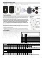
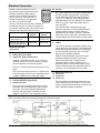
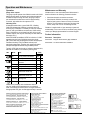
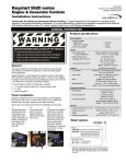
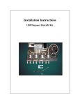
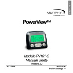
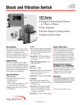
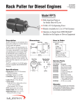
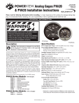
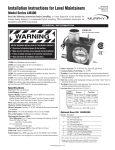
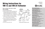
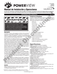
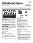
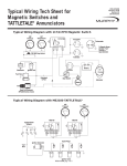
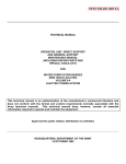
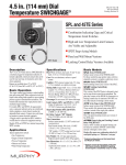
CANdrive™ 00-02-0618 revision H, 2015-07-13 section 80 CANbus SAE J1939 to Electric Gauge Interface Installation and Operating Instructions Please read the following information before installing. A visual inspection of this product for damage during shipping is recommended before installation. It is your responsibility to ensure that qualified mechanical and electrical technicians install this product. If in doubt, please contact your local Murphy or Enovation Controls representative. General Information W ARNIN G BEFORE BEGINNING INSTALLATION OF THIS PRODUCT Disconnect all electrical power to the machine Make sure the machine cannot operate during installation Follow all safety warnings of the machine manufacturer Read and follow all installation instructions Patent applied for GB2424280 As part of the MurphyLink® family, CANdrive offers a cost effective instrument solution for modern electronic engines. CANdrive modules read engine ECU CANbus/J1939 data, drive standard electric panel gauges, and provide LED indication of status and faults. CANdrive has three dedicated outputs for tachometer, oil pressure and coolant temperature gauges, with DIP switchselectable compatibility for Murphy, VDO or Datcon gauges. For volume orders, the outputs can be custom-configured for other gauge types, lamps, relays or remote signalling. CANdrive advantages include: the retrofitting of existing electric gauge panels to new, J1939 compatible engines the use of standard, economical electric gauges with new J1939 engines no need for installation of additional gauge senders, tachometer magnetic pickups and wiring. CANdrive is packaged in a compact, surface mounted case with epoxy encapsulation for maximum durability and environmental sealing. Electrical connection is via a 12-way automotive type connector. Model CDV100F has a forward facing connector and one power/CAN status LED. Model CDV300R has 8 LEDs for indication of J1939-transmitted engine faults and status. All models include a 6-way DIP switch for flexible configuration. Standard models & accessories Stock code 79.70.0104 Description CDV100F, CANdrive™ J1939 to gauge interface, 1 x CAN status LED, connector forward 79.70.0105 CDV300R, CANdrive™ J1939 to gauge interface, 8 x status/fault LEDs, connector rearward 78.00.0437 CDV-PW-30, 8 way wiring harness, length 30 in./760mm Specifications Power supply Operating voltage, 12V range (switch S5 on/up): 7 to 16 VDC 24V range (switch S5 off/down): 19 to 30 VDC Current consumption: CDV100: 25 mA typ. CDV300: 50 mA typ. (2 LEDs lit) Inputs CANbus: SAE J1939 protocol. Input has a 120 Ohm terminating resistor, removable by switch S4. Outputs (all ratings non-reactive) Oil pressure gauge, engine temperature gauge: switch selectable for Murphy, VDO or Datcon gauges: see Gauge Compatibility section for pressure/temperature verses equivalent sender resistance tables Tachometer: pulsed DC, 119 Hz ±1% @ 1500 RPM Physical Electromagnetic compatibility: 2004/108/EC Case material: polycarbonate / polyester / epoxy encapsulation Overall dimensions (w x h x d): 68 x 92 x 22mm / 2.7 x 3.7 x 0.9 in. (allow 50mm / 2.0 in. depth with connector) Weight: approx 80g / 0.2 lb Temperature: operation: –40 to +85°C / –40 to +185°F, 70% RH storage: –55 to +105°C / –67 to +221°F Environmental sealing: IP60 (CDV300R: IP65 from front with optional CDVG gasket) Vibration: 15g, 10 to 2000 Hz, 3-axis Shock: 50g, 11 mS, 3-axis Stock code 79.70.1003 78.70.0363 78.70.0364 79.70.1001 79.70.1002 Description CDVG, optional sealing gasket for CDV300R CDV100F plus CDV-PW-30 harness CDV300R, CDV-PW-30 and CDVG gasket CANdrive connector plug shell Connector pins for above (pack of 50) In order to consistently bring you the highest quality, full featured products, we reserve the right to change our specifications and designs at any time. MURPHY products and the Murphy logo are registered and/or common law trademarks of Enovation Controls LLC. This document, including textual matter and illustrations, is copyright protected by Enovation Controls Ltd., with all rights reserved. © 2015 Enovation Controls Ltd. A copy of the product warranty may be viewed or printed by going to http://www.fwmurphy.com/warranty. General Information (cont.) CDV100F front view CDV300R front view Rear view System connection Panel Installation CANdrive modules are surface-mounted with 4 x no.4 screws, fixing centre dimensions as shown. Select screw length according to panel thickness, ensuring a maximum of 13mm (½ inch) screw depth into the CANdrive fixing holes. Dimensions mm (in.) Model CDV100F, with forward facing connector, is designed for surface mounting inside an enclosed panel. Model CDV300F, with 8 LED indicators and rearward facing connector, is designed for front-of-panel mounting: this module requires an additional 60 x 40mm (2.4 x 1.6 in.) panel cut-out for rear access to connector and switches. A CDV300F with optional gasket CDVG (fitted into a well behind the case rim) provides IP65 front-of-panel environmental sealing. Before installing, ensure that the final mounting location meets operating temperature and environmental sealing requirements, and allows access for: a) connection of the wiring harness b) configuration of DIP switches S1 to S5 (location as shown above right). Alternatively, set these switches before panel fixing – see Configuration section below for full details. Configuration DIP switches S1 to S5 allow OEM- or user-configuration of CANdrive operating options. Switch S6 is not used. CANdrive is supplied with all switches in the ON (up) position. Switch settings must be made as appropriate, according to the configuration table right. Adjustment of the switch positions must be made while CANdrive is powered down. ▲ on (up) Switch position ▼ off (down) S1 S2 S3 S4 S5 ▲ ▲ ▲ ▼ ▲ ▲ ▼ ▲ ▼ ▲ ▼ ▲ ▲ ▼ ▼ ▲ ▼ ▲ ▼ Options: Murphy EG(S) temp. and pressure gauges Datcon temp. and 0 – 7 bar pressure gauges Datcon temp. and 0 – 10 bar pressure gauges VDO temp. and 0 – 5 bar pressure gauges VDO temp. and 0 – 10 bar pressure gauges CAN 120 Ohm terminating resistor in circuit CAN 120 Ohm terminating resistor removed 12V DC power supply 24V DC power supply Pressure gauge compatibility table: pressure versus approximate equivalent sender resistance (Ohms) Pressure psi 0 10 20 30 40 50 60 70 80 90 100 bar 0 0.7 1.4 2.1 2.8 3.4 4.1 4.8 5.5 6.2 6.9 Murphy ES series 240 205 171 143 123 103 88 74 60 47 33 Datcon 0 – 7 bar 240 195 160 140 115 100 82 68 55 43 35 Datcon 0 – 10 bar 240 215 190 168 150 135 118 107 97 87 77 VDO 0 – 5 bar 10 38 61 85 110 130 155 180 VDO 0 –10 bar 15 30 45 60 70 81 92 103 114 125 136 Temperature gauge compatibility table: temperature versus approximate equivalent sender resistance (Ohms) Temperature °C 40 50 60 70 80 90 100 110 120 130 140 °F 104 122 140 158 176 194 212 230 248 266 284 Murphy ES series 1029 680 460 321 227 164 120 89 74 52 40 Datcon 360 160 80 50 38 VDO 282.4 190.0 134.0 95.2 69.1 51.2 38.5 29.4 22.7 18.0 14.5 CANdrive installation and operation 110 7.6 1 0 8.3 130 9.0 140 9.7 67 58 50 42 148 160 170 182 00-02-0618 revision H 2015-07-13 p2/4 Electrical Connection CANdrive electrical connection is via a 12way automotive type receptacle shown right. CANdrive models are available with the connector facing forward through the front label (‘F’ option, e.g. model CDV100F), or rearward through the epoxy encapsulation (‘R’ option, e.g. model CDV300R). Pin Function 10 11 12 7 8 9 4 5 6 1 2 3 Pin 7 gives a square wave output (0V to battery positive DC), with a frequency proportional to engine speed. At 1500 RPM engine speed, the output frequency is 119 Hz (±1%), suitable for driving charge alternator based tachometers such as the Murphy ATA and ATHA series. Pin 7 gives no output when engine speed is below 100 RPM. An 8-way, 30”/270mm wiring harness is available as an additional loose item or as part of a CANdrive kit. For customer-made harnesses, part numbers for the mating connector plug and pins are as follows: Murphy part ref. Molex part ref. Connector plug shell x 1 (1 required per unit) 79.70.1001 03-09-1125 or 03-09-1126 Connector pins, pack of 50 (max 8 required per unit) 79.70.1002 02-09-1104 Connect each output to the appropriate gauge/ tachometer signal input. Connect gauge/tachometer negative terminals to battery negative, ideally via dedicated wiring to terminal 3. (The use of dedicated return wiring to pin 3, rather than a ground/earth return, minimises gauge inaccuracies caused by ground noise.) 5 8 Connect these terminals to the engine CANbus, taking care to observe the correct polarity. The CANbus cable shield/screen is typically connected to ground/earth at one end only (often at the ECU): refer to the engine manufacturer’s installation guidelines. Terminal functions Pin Function 1 2 3 Negative DC, power supply Positive DC, power supply Negative DC, gauge common return CANbus J1939 specifications require two 120 Ohm terminating resistors at each end of the network. CANdrive is supplied with a 120 Ohm network terminating resistor in circuit. If CANdrive is not positioned at the end of the CANbus network, switch out the terminating resistor by pushing DIP switch S4 off (down) – see Configuration section for details. CANdrive is supplied for use with 12V (7 to 16V) DC operation. If 24V (19 to 30V) DC operation is required, push DIP switch S5 to the off (down) position. Connect a 1 Amp anti-surge fuse in the positive DC line (pin 2). Pins 1 and 3 are internally linked: pin 1 is typically used as a power supply connection; pin 3 is typically used as a common negative return for the gauge outputs. 4 6 7 Oil pressure gauge output Coolant temperature gauge output Tachometer output Pins 4 and 6 give a variable current output for driving oil pressure and coolant temperature electric gauges. The current output versus pressure/temperature is specific to each gauge type, as selected using DIP switches S1, S2 and S3 – see Configuration section. CAN Hi CAN Lo 9 10 11 12 Reserved for future use Factory use Factory use Factory use These connections are reserved for future use, or are used in the factory setup of CANdrive. Do not connect wiring or equipment to these terminals: connection may result in permanent damage to CANdrive. Typical Connection Shown with Murphy EG(S) series gauges/Swichgages and AT(H)A tachometer. CANdrive installation and operation 00-02-0618 revision H 2015-07-13 p3/4 Operation and Maintenance Operation Maintenance and Warranty Gauge driver outputs The gauge outputs operate when CANdrive reads valid J1939 data for engine speed, oil pressure and coolant temperature. If CANdrive stops receiving valid data, the gauge outputs are maintained at the last known value for approximately 5 seconds, after which time the outputs turn off. CANdrive has no user-serviceable parts. Maintenance is therefore limited to the following preventative checks: Indicating LEDs All standard models have a green CAN LED. A flashing CAN LED indicates that CANdrive is powered, but is not receiving any J1939 data. A constantly lit CAN LED indicates power on with good CANbus connection and J1939 activity. (Note: J1939 activity can originate from ANY device on the CANbus network, and may not necessarily be valid data from the engine ECU.) Model CDV300R has additional LEDs for indication of J1939transmitted engine faults. CANdrive responds to single DM1 (active fault code) messages that contain SPN (Suspect Parameter Number), FMI (Fault Mode Indicator) and warning/stop lamp data. CANdrive also reads multi-packet transport messages broadcast using the BAM protocol. Check that electrical connections are secure. Check that the CANdrive is securely mounted, and kept free from ingress of water or build up of excessive dust/dirt. The front label and casing may be wiped with a clean, damp cloth. Do not use cleaning solvents. CANdrive is supplied with a 2 year warranty on parts and workmanship. In the event of a fault or technical query, please contact your Murphy representative for technical support. Further information Document Description 00-02-0251 EG(S)21 series electric gage installation 00-02-0258 AT series tachometer installation Typically, LEDs light continuously to indicate a shutdown fault, and flash to indicate a (non-shutdown) warning fault: LED Mode Fault On Low oil pressure shutdown Flashing Low oil pressure warning On Coolant temperature shutdown Flashing Coolant temperature warning On Overspeed shutdown Flashing Overspeed warning - Reserved for future use - Reserved for future use J1939 SPN FMI 100 1 100 > 1 110 0 110 > 0 190 0 190 > 0 - - Flashing Warning fault - - Flashing Shutdown fault - - CANdrive can handle up to 8 simultaneous faults at one time: additional fault messages are not registered. When a fault becomes inactive and is no longer broadcast, the appropriate LED goes out after approximately 2 seconds. ENOVATION CONTROLS CORPORATE HEADQUARTERS 5311 S 122ND EAST AVENUE, TULSA, OK 74146, USA ENOVATION CONTROLS – SAN ANTONIO OFFICE 5757 FARINON DRIVE, SAN ANTONIO, TX 78249, USA ENOVATION CONTROLS – HOUSTON OFFICE 105 RANDON DYER RD, ROSENBERG, TX 77471, USA ENOVATION CONTROLS LTD. – UNITED KINGDOM CHURCH ROAD, LAVERSTOCK, SALISBURY, SP1 1QZ, UK MURPHY ECONTROLS TECHNOLOGIES – CHINA 77 23RD STREET, HANGZHOU ECONOMIC & TECHNOLOGICAL DEVELOPMENT AREA, HANGZHOU, ZHEIJIANG 310018, CHINA CANdrive installation and operation SALES & SUPPORT, NORTH AMERICA MURPHY PRODUCTS: PHONE: 918 317 4100 FAX: 918 317 4266 EMAIL: [email protected] WWW.FWMURPHY.COM ECONTROLS PRODUCTS: PHONE: 210 495 9772 FAX: 210 495 9791 EMAIL: [email protected] WWW.ECONTROLS.COM MURPHY CONTROL SYSTEMS & SERVICES PHONE: 281 633 4500 FAX: 281 633 4588 EMAIL: [email protected] MURPHY INDUSTRIAL PANEL DIVISION PHONE: 918 317 4100 FAX: 918 317 4124 EMAIL: [email protected] SALES & SUPPORT, INTERNATIONAL EUROPE, MIDDLE EAST & AFRICA PHONE: +44 1722 410055 FAX: +44 1722 410088 EMAIL: [email protected] WWW.FWMURPHY.EU CHINA PHONE: +86 571 8788 6060 FAX: +86 571 8684 8878 EMAIL: [email protected] LATIN AMERICA & CARIBBEAN PHONE: +1 918 317 2500 EMAIL: [email protected] SOUTH KOREA PHONE: +82 70 7951 4100 EMAIL: [email protected] INDIA PHONE: +91 91581 37633 EMAIL: [email protected] FM 28221 (Tulsa, OK – USA) FM 28221 (Rosenberg, TX – USA) FM 620667 (San Antonio, TX – USA) FM 29422 (UK) FM 523851, TS 589322 (China) 00-02-0618 revision H 2015-07-13 p4/4