1
Use the
•
•
Installation and
Operating Instructions
Press
•
buttons to set the digit to the required
to return to the first level menu structure. Use
the
and
buttons to scroll up and down the menu
structure to adjust another parameter. If no other settings
are required, press
to exit set-up mode and return to
measurement mode.
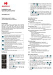
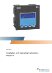
Quikwire PS3
Digital energy meter for single
and three-phase electrical systems
Setup Menu Structure
Change password
nnnn - 4-digit number – default ‘0000’
Supply systems
3-phase 4-wire or Single phase
Introduction
Havells Quikwire solution revolutionises meter installation
within panel board applications utilising plug and play
technology. This manual will provide all the necessary
instructions to install and operate this instrument. Additional
information regarding assembly within the panel board can be
found at the end of this manual.
Measurement
In measurement mode, the buttons control the displayed
measurement as follows:
Selects the Voltage and Frequency display screens.
Successive operations of the button select voltage,
frequency, and %THD (Total Harmonic Distortion).
In set-up mode, this is the ‘Back’ button.
Selects the Current display screens. Successive
operations select phase and neutral (3ph4w) currents, max.
demanded currents, and current %THD.
In set-up mode, this is the ‘Up’ button.
Selects the Instantaneous Power screens. Successive
operations select power (W, VAr & VA), max. demanded
power, and power factor.
In set-up mode, this is the ‘Down’ button.
Selects the Energy display screens. Successive operations
select imported Wh and Varh. Display can indicate up to
9999999·9.
CT Set maximum current that can be monitored according to
CT in use, nnnn – 4-digit number 0001 to 9999
Demand Interval Time
Selects demand time in minutes – 60/30/20/15/10/8/5/OFF
Reset
Setting up
Press and hold the two outermost buttons
and
simultaneously for five
seconds until the password screen is
displayed.
•
Press
four times to enter the default
password of “0000”.
•
The system setup screen will be displayed
on the screen. Press the
button to scroll
down the menu until you see the CT primary
setting screen.
•
Press the
button to enter the CT
primary setting screen. The first digit
should start flashing.
Resets cumulative energy and Demand
measurements to zero
Communication parameters for RS485 interface
Modbus™ protocol
Baud rate 2400/4800/9600/19200/38400
Parity none/odd/even
Stop bits 1 (1 or 2 if parity is none)
RS485 network address nnn – 3-digit number 1 to 247
Order – Norm/Rev indicates if the Modbus™ word
order is normal or reversed.
Johnson Controls (JC) N2 protocol
RS485 network address nnn – 3-digit number 1 to 255
Relay pulse output
kWh/kVArh/Off (Active/reactive – Import only)
Rate 1/10/100/1000/10,000 kWh or kVArh per pulse
Pulse width 200/100/60 ms
Default ON selects default kWh screen at startup and fall-back.
OFF selects screen chosen remotely via Modbus™.
Energy kilo / Mega
Test
Phase sequence
Display on – all elements on to check display
Display toggle - Each element is turned on and off
SOFT
Displays firmware version numbers
In set-up mode, this is the ‘Enter’ button.
•
and
value then press
to confirm. Repeat this process until
all four digits have been set to the desired CT primary
value (e.g. 100A = 0100A, 1000A = 1000A).
The word “SET” will be displayed after the fourth digit has
been entered to confirm that the primary CT value has
been set.
Menu Option Selection
1.
After entering the correct password, use the
and
buttons to navigate up and down the first level until the
desired parameter is reached. Selection does not roll over
from bottom to top of list or vice versa.
2.
Press the
button to select the desired parameter and
enter the second level menu structure.
3.
If an item flashes then it can be adjusted by the
and
keys. If not, there may be a further layer, e.g. Comms Baud rate, before adjustment is possible. Press
to
select the lower layer.
4.
Having selected an option from the current menu layer,
press
to confirm your selection. The SET indicator will
appear.
5.
Once all the necessary selections have been made and the
to return to the first level
required settings entered, press
menu structure. The word SET will go off and one can then
use the
and
keys for further menu selection.
Warnings
Caution: Risk of Electric
Shock
•
During normal operation, voltages hazardous to life
may be present at some of the terminals of this unit.
•
At voltages below that specified in the Range of Use
the meter may shut down.
However, voltages
hazardous to life may still be present at some of the
terminals of this unit.
Number Entry Procedure
•
When setting up the unit, some screens require the entry of a
number. In particular, to enter the setting up section a password
must be entered. Digits are set individually, from left to right.
The procedure is as follows:
Installation and servicing should be performed only
by qualified, properly trained personnel abiding by
local regulations.
•
Ensure all supplies are de-energised
attempting connection or other procedures.
1.
•
Terminals should not be user accessible after
installation and external installation provisions must
be sufficient to prevent hazards under fault
conditions.
•
This unit is not intended to function as part of a
system providing the sole means of fault protection good engineering practice dictates that any critical
function be protected by at least two independent
and diverse means.
•
The unit does not have internal fuses therefore
external fuses must be used for protection and
safety under fault conditions.
•
Never open-circuit the secondary winding of an
energized current transformer.
•
This product should only be operated with CT
secondary connections Earthed.
•
If this equipment is used in a manner not specified
by the manufacturer, protection provided by the
equipment may be impaired.
•
Auxiliary circuits (communication & relay outputs)
are separated from the metering inputs by at least
basic insulation. Such auxiliary circuit terminals are
only suitable for connection to equipment which has
no user accessible live parts. The insulation for
such auxiliary circuits must be rated for the highest
voltage connected to the instrument and suitable for
single fault condition. The connection at the remote
end of such auxiliary circuits should not be
accessible in normal use. Depending on application,
equipment connected to auxiliary circuits may vary
widely. The choice of connected equipment or
combination of equipment should not diminish the
level of user protection specified.
6.
On completion of all setting-up, press
repeatedly until
the measurement screen is restored. If no other setting is
required, press
to exit set-up mode and return to
measurement mode.
The current digit to be set flashes and is set using the
and
2.
3.
keys.
Press
to confirm each digit setting. The word SET will
be displayed once the last digit has been set.
After setting the last digit, press
setting routine.
to exit the number
Installation
3 Phase, 4 wire
L1
N
LOAD
1A FAST
BLOW
FUSE
L1
L2 L3
V OUT
N
MODBUS
B A GND
L1
L2 L3
V IN
VOLTAGE
PASS-THROUGH
TO NEXT METER
IN CHAIN
VOLTAGE
PASS-THROUGH
TO NEXT METER
IN CHAIN
Single Phase, 2 wire
L1
L2
L3
N
L1
N
S1
P1
L2 L3
V OUT
N
MODBUS
B A GND
PULSE
L1
L2 L3
V IN
N
PULSE
+I1-+I2-+I3-
+I1-+I2-+I3-
L1
N
LOAD
1A FAST
BLOW
FUSES
LOAD
L1
L2
L3
N
S1
P1 S1
P1 S1
P1
LOAD
The unit may be mounted in a panel of any thickness up to a
maximum of 6mm (0·25in). Leave enough space behind the
instrument to allow for bends in the connection cables. As the
front of panel enclosure conforms to IP52, it is protected from
dripping water. The unit is intended for use in a reasonably
stable ambient temperature within the range -10 to +55°C. Do
not mount the unit where there is excessive vibration or in
excessive direct sunlight.
As the unit derives its internal power from phase L1 of the
measuring voltage, for operation terminals L1 and N must always
be connected and the applied voltage must be kept within the
specified range of use.
•
The supply to the unit should not be subject to excessive
interference. In some cases, a supply line filter may be
required.
•
To protect the product against incorrect operation or
permanent damage, surge transients must be controlled. It
is good EMC practice to suppress transients and surges at
the source. The unit has been designed to automatically
recover from typical transients; however in extreme
circumstances it may be necessary to temporarily disconnect
the supply for a period of greater than 10 seconds to restore
correct operation.
•
Screened communication leads are recommended and may
be required. These and other connecting leads may require
the fitting of RF suppression components, such as ferrite
absorbers, line filters etc., if RF fields cause problems.
•
It is good practice to install sensitive electronic instruments
that are performing critical functions in EMC enclosures that
protect against electrical interference causing a disturbance
in function.
Safety
The unit is designed in accordance with BS EN 61010-1:2001
(IEC 61010-1:2001) – Permanently connected use, Normal
condition. Installation category III, pollution degree 2, basic
insulation for rated voltage. Measurement Category III.
EMC Installation Requirements
Whilst this unit complies with all relevant EU EMC (electromagnetic compatibility) regulations, any additional precautions
necessary to provide proper operation of this and adjacent
equipment will be installation dependent and so the following can
only be general guidance:
•
Avoid routing wiring to this unit alongside cables and
products that are, or could be, a source of interference.
before
Wiring
Connections are made via two-part connectors with screw clamp
terminals. Choice of cable should meet local regulations for the
operating voltage and current. The current inputs of this
product are designed for connection into systems via
current transformers only. Instrument transformers used for
connection to the meter must be of approved type and compliant
with ANSI/IEEE C57.13 or IEC 60044-1, selected and sized
appropriate to the supply network being monitored. All negative
current inputs are commoned inside the unit. To minimise
measurement errors the CTs should be grounded at one point
only, as shown in the wiring diagram. CT secondaries must be
grounded in accordance with local regulations. It is desirable to
make provision for shorting links to be made across CTs to
permit easy replacement of a unit should this ever be necessary.
Connector plugs are suitable for copper wires only and will
2
accept one stranded 0·05 – 2·5mm (30 - 12AWG) stranded or
solid core cables.
This instrument is intended for panel
mounting. Terminals must be enclosed within the panel. For
mains terminals use wire rated at 600V, 60°C minimum
temperature. Terminal screws are fully tightened for shipment
and must be undone before wire insertion. Terminal screws
should be tightened to 0·5 Nm (4·4 lbf in) only.
Fusing
This unit must be installed with external fuses in the voltage
supply lines of type fast blow 1A maximum. Choose fuses of a
type and with a breaking capacity appropriate to the supply and
in accordance with local regulations.
A suitable switch or circuit breaker conforming to the relevant
parts of IEC 60947-1 and IEC 60947-3 should be included in the
installation. It should be positioned so as to be easy to operate,
in close proximity to the equipment, and clearly identified as the
disconnecting device.
Specification
Measurement Inputs
Imported energies are recorded.
Three current inputs (six physical terminals) with 2·5mm
stranded wire capacity for connection of external CTs.
Voltage inputs and outputs through 4-way connectors with
2
2·5mm stranded wire capacity. 3-Phase 4-wire unbalanced and
Single-phase 2-wire. Line frequency measured from L1 voltage
or L3 voltage.
Direct measurement of 173 to 500Vac L-L (100 to 289Vac L-N).
Range of Use
Values of measured quantities, components of measured
quantities, and quantities which affect measurement errors to
some degree, for which the product gives meaningful readings:
Voltage
31 … 120% of Range Maximum
Current
1 … 120% of nominal
Active power
1 … 144% of nominal, 360MW maximum
Apparent power
1 … 144% of nominal, 360MVA maximum
Power is only registered when voltage and current are within
their respective range of use.
Accuracy
Voltage (V)
0·5% of range maximum
Current (A)
0·5% of range maximum
Neutral current
calculated (A)
4% of range maximum
Frequency (Hz)
0·11 Hz
Earth/Ground Connections
Power factor (PF)
1% of unity
For safety reasons, current transformer secondary connections
should be grounded in accordance with local regulations. Under
no circumstances should the product be operated without this
Earth connection.
Active power (W)
± 1% of range maximum
Maintenance
In normal use, little maintenance is needed. As appropriate for
service conditions, isolate from electrical power, inspect the unit,
and remove any dust or other foreign material present.
Periodically check all connections for freedom from corrosion and
screw tightness, particularly if vibration is present.
The front of the case should be wiped with a dry cloth only. Use
minimal pressure, especially over the viewing window area. If
necessary wipe the rear case with a dry cloth. If a cleaning agent
is necessary, isopropyl alcohol is the only recommended agent
and should be used sparingly. Water should not be used. If the
rear case exterior or terminals should be contaminated
accidentally with water, the unit must be thoroughly dried before
further service. Should it be suspected that water might have
entered the unit, factory inspection and refurbishment is
recommended.
2
Reactive power (VAr)
± 1% of range maximum
Apparent power (VA)
± 1% of range maximum
Active energy (kWh)
Class 1 (IEC 62053-21) section 4.6
Reactive energy (kVArh)
± 1% of range maximum
THD
1% up to 31 harmonic
Response time to step
input
1s typical to >99% of final value
st
Pulsed output relays
Contact rating
50mA max at 250V AC/DC
for general switching applications
Type
Solid state relay
RS485 output
Type
2-wire half duplex
Baud rate
2400, 4800, 9600, 19200, 38400
*Ensure any external circuits connected to either relay or RS-485
output modules are provided with double/reinforced insulation.
Reference Conditions of Influence Quantities
Influence Quantities are variables that affect measurement errors
to a minor degree. Accuracy is verified under nominal value
(within the specified tolerance) of these conditions.
Ambient temperature
23°C ±1°C
Input waveform
50 or 60Hz ±2%
Input waveform
Sinusoidal (distortion factor
<0·005)
Magnetic field of external
origin
Terrestrial flux
Environment
*
Operating temperature
-10°C to +55°C
*
Storage temperature
-20°C to +70°C
*
Maximum operating and storage temperatures are in the context
of typical daily and seasonal variation.
Mechanics
Dimensions
96 × 96 mm (L×W)
Depth (behind panel) 61 mm maximum
Case protrusion
6·5 mm maximum
(front of panel)
Sealing
IP52 (front panel), IP30 (case) (minimum)
Mounting
DIN 96 panel mounting
Approval, Certification, and Standards Compliance
EMC, Emissions
BS EN 61326, Class A (Industrial)
EMC, Immunity
BS EN 61326, Class A (Industrial)
Safety
BS EN 61010-1:2001
Specification Input
Nominal input voltage
100 to 289V AC L-N
Max. continuous input
overload voltage
120% of nominal
Max. short duration input
voltage
2 x range maximum
(1 second application repeated
5 times at 5 minute intervals)
Relative humidity
0 to 90%, non-condensing
Altitude
Up to 2000m
Warm up time
1 minute
Vibration
10Hz to 50Hz, IEC 60068-2-6, 2g
Shock
30g in 3 planes
Nominal input voltage burden
Dielectric voltage
withstand test
2.2kV rms 50Hz for 1 minute between
Measuring Voltage Inputs to RS485
and Relay.
5VA nominal L1-N,
< 0·2VA all other phases
Nominal input current
5A AC rms
Max. continuous input
overload current
120% of nominal
Max. short duration input
current
10 x nominal
(1 second application repeated
5 times at 5 minute intervals)
Frequency
45 to 66Hz
Front Face Only
Havells Quikwire solution revolutionises meter installation
within panel board applications utilising plug and play
technology.
The following instructions provide detailed guidelines on
how to install Havells Quikwire metering solution into
PowerSafe MCCB panelboards
1.0. Incoming Metering (PSPBS250SW, PSPBS400SW, PSPB630SW)
1.1. CT Fitment – 250A
Fig 2
Step 1: Remove Incoming MCCB shroud. Remove CT
shorting link and retain for future use as per figure 1.
Fig 1
Step 2: Connect CT Loom to CT by pushing plug
connector as per figure 2 and fastened as necessary.
Step 3: Align CT ground cable ring terminal with CT
mounting foot and place fastener to retain grounding
cable.
Step 4: Fit CT to mounting plate using the supplied
fasteners. This can be completed before or after cables
have been passed through CT aperture.
1.2. CT Fitment – 400/630A
Fig 3
Step 1: Fit mounting kit with CT direct to mounting plate
as shown, fig 3
Step 2: Pass copper palms through CT aperture and
fasten to torque setting accordingly fig 4.
Fig 4
1.3. Incoming Meter Fitment
Step 1: Fit side extension box to panel board using the
fasteners supplied and remove bottom meter blank as
necessary.
Step 2: Fit meter into available cut out. Note the meter has
no additional fixing fasteners and is retained by moulding
Fig 5
integral to the casing, fig 5.
Step 3: Fit CT loom to meter at bottom connector position
as per figure 6.
Step 4: Fit meter loom to main voltage tap off fuse loom
and terminate to connector position V IN. IF outgoing
metering is also used then voltage should be supplied from
the nearest outgoing meter (follow meter looping
instructions section 2.3)
Fig 6
2.0. Outgoing Metering (PSPBL160SW, PSPBL250SW)
2.1. CT Fitment
Fig 8
Step 1: Remove CT shorting link and retain for future
use as per figure 7.
Step 2: Connect CT Loom to CT by pushing plug
connector as per figure 8 and fastened as necessary.
Step 3: Align CT ground cable ring terminal with CT
mounting foot and place fastener to retain grounding
cable.
Step 4: Fit CT to mounting plate using the supplied
fasteners. This can be completed before or after
cables have been passed through CT aperture.
Note: CT connector should always face away from MCCB
and denoted LHS for mounting of left hand side of panel
board or RHS when mounting on right hand side of panel
board
Fig 7
2.2. Meter Fitment
Step 1: Fit side extension box to panel board using
the fasteners supplied and remove meter blank as
Fig 9
necessary, fig 9
Step 2: Fit meter into available cut out. Note the
meter has no additional fixing fasteners and is
Fig 10
retained by moulding integral to the casing, fig 10.
Step 3: Fit CT loom to meter at bottom connector
Fig 11
Fig 13
position as per fig 11.
Step 4: Fit meter loom to main voltage tap off fuse
loom supplied within panelboard and terminate to
connector position V IN, fig 12 & 13.
Fig 12
2.3. Looping meter supply
Step 1: Locate connector on first meter marked V
Fig 14
Out. Using meter loom connect to next meter marked
V IN, fig 14 and fig 15
Step 2: Replicate as necessary and dress cables as
desired using supplied cable tie accessories. Where
Fig 16
possible utilize side extension inner tray to keep
cables away from obstructions, fig 16.
Fig 15
Note: When using surge protection kit, the surge protection
device should be fitted on the mounting bracket provided
within the side extension box. In this case the next available
meter position should be used.
Using Non Quikwire meters
Pulse/ RS485 connection
Plug connectors can be remove simply by pressing
the orange release button.
Remove the Pulse/RS485 male connector and simply
push cables into the corresponding terminal position
as labelled. Connect to meter as necessary.
For single phase application please contact the office
Havells Sylvania UK Ltd.
Avis Way,
Newhaven,
East Sussex,
BN9 0ED
Customer Service: 0843 22 753 88
www.havells.co.uk
Project 2205. Drawing No. CI-3K62901 Rev.2 DMR 2775 10/10/12