1
Installation manual
Washer extractor
W575S, W585S, W5105S, W5130S, W5180S,
W5250S, W5330S
Type W3...
Original instructions
438 9055-40/EN
2013.02.21
Contents
Contents
1 Safety Precautions ............................................................................................................. 5
1.1 Symbols...................................................................................................................... 5
2 Technical data .................................................................................................................... 6
2.1 Drawing ...................................................................................................................... 6
2.1.1 W575S, W585S, W5105S, W5130S................................................................... 6
2.1.2 W5180S .............................................................................................................. 7
2.1.3 W5250S, W5330S .............................................................................................. 8
2.2 Technical data............................................................................................................. 9
2.3 Connections................................................................................................................ 9
2.4 Sound levels ............................................................................................................... 9
3 Setup.................................................................................................................................. 10
3.1 Unpacking................................................................................................................... 10
3.2 Siting........................................................................................................................... 11
3.3 Mechanical installation ............................................................................................... 12
3.3.1 Casting a plinth ................................................................................................... 14
3.3.2 Chemical bolts .................................................................................................... 15
3.3.3 Chemical anchors ............................................................................................... 16
4 Marine installation .............................................................................................................. 17
4.1 Siting........................................................................................................................... 17
4.2 Mechanical installation ............................................................................................... 18
4.2.1 Casting a plinth ................................................................................................... 19
4.2.2 Welding a foundation .......................................................................................... 20
5 Water connection ............................................................................................................... 21
6 Connection of external dosing systems ............................................................................. 23
6.1 Connection of the hoses............................................................................................. 23
6.2 Electrical connection of external dosing system......................................................... 24
6.2.1 Machine with connectors .................................................................................... 24
6.2.2 Machine without connectors ............................................................................... 25
6.2.3 Outputs ............................................................................................................... 26
6.2.4 Inputs .................................................................................................................. 28
7 Drain connection ................................................................................................................ 29
8 Electrical connection .......................................................................................................... 30
8.1 Electrical installation ................................................................................................... 30
8.2 Electrical connections................................................................................................. 31
8.3 Machine connection.................................................................................................... 36
8.3.1 Single-phase connection..................................................................................... 36
8.3.2 Three-phase connection ..................................................................................... 37
8.4 Functions for I/O-cards ............................................................................................... 38
8.4.1 External coin meter/Central payment (2A).......................................................... 38
8.4.2 Central payment (2B).......................................................................................... 39
8.4.3 Central payment (2C).......................................................................................... 40
8.4.4 Outputs for detergent signals and inputs for pause signals, "empty" signal
and price reduction (2D) .................................................................................... 41
8.4.5 Central booking/payment (2F) ............................................................................ 42
8.4.6 Machines with I/O module type 3........................................................................ 43
9 Steam connection .............................................................................................................. 44
10 Selection of language....................................................................................................... 46
Contents
11 Function check ................................................................................................................. 47
The manufacturer reserves the right to make changes to design and component specifications.
Safety Precautions
1 Safety Precautions
The machine is only intended for water-wash use.
Only use detergent intended for water-wash of textiles. Never use dry cleaning agents.
Do not allow minors to use the machine.
Do not hose down the machine with water.
The machine's door lock must under no circumstances be bypassed.
If the machine develops a fault, this must be reported to the person in charge as soon as possible. This is
important both for your safety and that of others.
This appliance can be used by children aged from 8 years and above and persons with reduced physical,
sensory or mental capabilities or lack of experience and knowledge if they have been given supervision or
instruction concerning use of the appliance in a safe way and understand the hazards involved. Children
shall not play with the appliance. Cleaning and user maintenance shall not be made by children without
supervision.
Children of less than 3 years should be kept away unless continuously supervised.
DO NOT MODIFY THIS APPLIANCE.
All external equipment which is connected to the machine must be CE/EMC-approved and connected using
an approved shielded cable.
All external equipment must be connected according to the instructions in the installation manual.
In order to prevent damage to the electronics (and other parts) that may occur as the result of condensation,
the machine should be placed in room temperature for 24 hours before being used for the first time.
Servicing shall be carried out only by authorized personnel.
Only authorized spare parts shall be used.
When performing service or replacing parts, the power must be disconnected.
1.1 Symbols
Caution
Caution, hot surface
Read the instructions before using the machine
5
Technical data
6
2 Technical data
2.1 Drawing
2.1.1 W575S, W585S, W5105S, W5130S
I
M
A
3
B
1
10
G
4
5
11
J
6
8
9
2
C
K
H
L
F
D
N
E
7
O
fig.7649A
1
Operating panel
2
Door opening, W575S, W585S: ⌀ 310 mm, W5105S, W5130S: ⌀ 365 mm
3
Detergent container
4
Cold water
5
Hot water
6
Water re-use
7
Drain valve
8
Liquid detergent supply
9
Electrical connection
10
Steam connection
mm
A
B
C
D
E
F
G
H
W575S
660
1094
1131
355
686
835
80
1034
W585S
660
1157
1132
355
726
836
80
1035
W5105S
720
1187
1200
365
697
920
80
1119
W5130S
720
1326
1201
365
787
920
80
1119
I
J
K
L
M
N
O
W575S
217
124
1014
914
278
101
199
W585S
217
124
1015
915
278
103
199
W5105S
224
124
1099
999
278
105
212
W5130S
224
124
1099
999
278
103
212
mm
Technical data
7
2.1.2 W5180S
I
M
1
A
3
B
G
4
P
10
5
6
J
8
9
2
C
L
F
D
K
H
N
E
O
7
fig.7783
1
Operating panel
2
Door opening, W5180S
3
Detergent container
4
Cold water
5
Hot water
6
Water re-use
7
Drain valve
8
Liquid detergent supply
9
Electrical connection
10
Steam connection
mm
W5180S
mm
W5180S
A
B
C
D
E
F
G
H
751
1431
1344
435
875
1048
81
1249
I
J
K
L
M
N
O
P
297
132
1229
1129
278
104
231
217
Technical data
8
2.1.3 W5250S, W5330S
I
M
A
B
1
3
J
4
G
P
5
6
10
8
1
Q
2
C
L
F
D
K
H
N
E
7
O
fig.7650A
1
Operating panel
2
Door opening, W5250S, W5330S: ⌀ 435 mm
3
Detergent container
4
Cold water
5
Hot water
6
Water re-use
7
Drain valve
8
Liquid detergent supply
9
Electrical connection
10
Steam connection
mm
A
B
C
D
E
F
G
H
W5250S
830
1594
1425
470
949
1129
80
1328
W5330S
910
1679
1464
500
1034
1034
80
1367
I
J
K
L
M
N
O
P
Q
W5250S
327
233
1288
1203
278
100
264
162
287
W5330S
347
247
1327
1247
278
104
210
162
287
mm
Technical data
9
2.2 Technical data
W575S
W585S
W5105S
W5130S
W5180S
W5250S
W5330S
kg
129
135
145
175
228
287
330
litres
75
85
105
130
180
250
330
Drum diameter
mm
520
520
595
595
650
725
795
Drum speed during wash
rpm
49
49
49
49
44
44
42
Drum speed during
extraction
rpm
830
830
776
776
742
702
641
200
200
200
200
200
200
200
kW
5.4
5.4
5.4
7.5
13
18
23
kW
7.5
7.5
7.5
10
Weight, net
Drum volume
G-factor, max.
Heating: Electricity
kW
10
Heating: Steam
x
x
x
x
x
x
x
Heating: Hot water
x
x
x
x
x
x
x
Frequency of the dynamic
force
Hz
13.8
13.8
12.9
12.9
12.4
11.7
11.2
Floor load at max
extraction
kN
1.6 ± 2.4
1.7 ± 2.6
1.9 ± 3.0
2.3 ± 3.8
3.0 ± 4.8
3.8 ± 5.9
4.3 ± 6.9
W575S
W585S
W5105S
W5130S
W5180S
W5250S
W5330S
2.3 Connections
Water valves
DN
BSP
20
3/4”
20
3/4”
20
3/4”
20
3/4”
20
3/4”
20
3/4”
20
3/4”
Recommended water
pressure
kPa
200–600
200–600
200–600
200–600
200–600
200–600
200–600
Functioning limits for
water valve
kPa
50–1000
50–1000
50–1000
50–1000
50–1000
50–1000
50–1000
Capacity at 300 kPa
l/min
20
20
20
20
30
60
60
mm
75
75
75
75
75
75
75
Draining capacity
l/min
170
170
170
170
170
170
170
Steam valve connection
DN
BSP
15
1/2”
15
1/2”
15
1/2”
15
1/2”
15
1/2”
15
1/2”
15
1/2”
Recommended steam
pressure
kPa
300–600
300–600
300–600
300–600
300–600
300–600
300–600
Functioning limits for
steam valve
kPa
50–800
50–800
50–800
50–800
50–800
50–800
50–800
Drain valve
⌀ outer
2.4 Sound levels
The sound power level of the machine is determined by using ISO 3747:2012.
According to test code IEC 60704-2-4 the sound power level at extraction and during washing
are according to the table:
W575S
W585S
W5105S
W5130S
W5180S
W5250S
W5330S
Wash
dB(A)
64
64
63
63
70
67
68
Extraction
dB(A)
75
75
71
72
74
76
75
Setup
10
3 Setup
3.1 Unpacking
Note!
For W5130S-W5330S two persons are recommended for the unpacking.
The machine is delivered complete with expander bolts etc.
The machine is delivered bolted onto the transport pallet and packed in a crate or box.
Remove packing from the machine.
Remove the front and rear panel.
Remove the bolts between the machine and pallet. There is one to the right in the front of the
machine and another diagonally opposed to it, at the back of the machine.
①
fig.7651
Remove the machine from the pallet.
Note!
When moving the machine, handle it with care.
Place the machine on its final position.
Setup
11
3.2 Siting
Install the machine close to a floor drain or open drain.
The machine should be positioned so that there is plenty of room for working, both for the user
and service personnel.
The figure shows minimum distance to a wall and/or other machines.
②
25 mm /
1 inch
25 mm /
1 inch
500 mm /
20 inch
fig.W00176D
Setup
12
3.3 Mechanical installation
If the machine is not to be mounted on a base the machine must be fastened to the floor.
The table shows the correct drilling points.
Mark and drill four holes in the positions shown.
Note!
Two expander bolts MUST also be fitted to the front section of the machine. If not, large
vibrations in the machine cabinet may occur.
Mark and drill two holes (⌀ 10 mm) about 40 mm deep (1) for the expander bolts in the positions
shown.
③
B
A
F
D
I
E
H
1
1
G
C
=
=
fig.0948A
mm
A
B
C
D
E
F
G
H
I
W575S
685
660
495
395
115
635
495
-
75
W585S
725
660
495
445
115
665
495
-
75
W5105S
700
720
575
385
120
695
595
10
80
W5130S
785
720
575
495
120
760
595
10
80
W5180S
875
750
635
570
120
855
655
10
85
W5250S
950
830
715
635
125
955
740
10
85
W5330S
1035
910
790
695
135
1050
810
10
95
After the machine has been placed over the other four bolts, place the two spacer washers over the
two holes. They shall be placed between the machine and foundation.
Insert the expansion bolts supplied into all of the holes drilled in the floor. Fit the washers and
nuts and tighten well.
Setup
13
Level the machine by using stainless or galvanized steel washers between the machine and the
floor. The washers must be of a size to cover the support surface. Fit the washers and self-locking
nuts supplied with the machine and tighten well. To tighten the nuts it is recommended to use a
rachet wrench, especially in the right rear corner.
It is of the upmost importance that the machine is placed in level, from side to side as well as front to rear. If
the machine is not properly levelled, it may result in out-of-balance without a real out of balance in the drum.
④
fig.5463A
After the machine has been in use for a while, check and re-tighten the nuts if necessary.
Floor
In this type of machine, the drum is attached directly to the frame. As a result the floor under the
machine must be stable enough to absorb the dynamic forces generated during spin cycles. For
that reason, the mounting bolts must be cast into the floor material itself.
When fixing the machine to an existing cement floor, it must be and at least 100 mm thick. If the
floor is less than 100 mm thick, an alternative might be to cast a plinth.
The floor must be able to withstand the loads indicated in the technical data table.
If it isn’t possible to cast the bolts into the floor, an alternative might be to use so-called chemical
anchors.
Setup
14
3.3.1 Casting a plinth
A plinth should be used where the existing floor is less than 100 mm thick or in order to ensure that
the machine is above the level of any water leakages.
The plinth should be approximately 150 - 200 mm in height.
⑤
150-200 mm /
5 7/8-7 7/8 inch
40 mm /
1 9/16 inch
fig.5462
Proceed as follows:
• Break up the existing floor to a depth of approx. 75 mm and check that the sides of the hole are
tapered outward so that the longest side at the bottom measures 120 mm more than at the top.
⑥
75
a
20
a+1
fig.0899
• Make the mould for the plinth.
• Moisten the hole well and apply cement to the sides and bottom.
• 4 bolts must be set into the concrete of the machine base. The bolts need to project 40 mm out
of the base. Pour the concrete into the prepared base mould and make sure that the surface is
level. Check the previous table for the correct position of the bolts.
• The concrete should be left to set for at least two days before mounting the machine on the plinth.
Setup
15
3.3.2 Chemical bolts
An alternative to breaking up the existing floor or foundation is to use chemical bolts M16.
1. Mark and drill four holes (⌀ 18 mm) 125 mm deep for the chemical bolts.
Check the previous table for the correct position of the holes.
2. Clean the drilled holes.
3. Put down the chemical ampule in the hole.
4. Rotate the bolt into the hole, so that the glass ampule is broken and its contents mixed.
5. Rotate the bolt to correct depth.
Note!
Do not rotate the bolt against the concrete bottom. Check that the chemicals have filled
the hole completely.
6. Remove the drilling machine with the mounting tool. Hold the bolt with one hand. Let the bolt
harden before the machine is mounted.
⑦
1
2
3
4
5
6
fig.5917A
Time for hardening, due to different concrete temperatures:
– 10°C: 6 hours
– 5°C: 2.5 hours
± 0°C: 1 hour
5°C: 30 minutes
10°C: 20 minutes
15°C: 15 minutes
20°C: 10 minutes
Setup
16
3.3.3 Chemical anchors
If installation shall be done on vinyl floor coverings chemical anchors shall be used.
1. Mark and drill four holes for the chemical anchors.
Check the previous table for the correct position of the holes.
2. Cut the flooring material around the washers
3. Apply sealant to the hole cut in the vinyl floor covering. Insert the washer. Use sealant to seal
around the washer between the vinyl and the washer.
4. Put the machine into place.
Check that the machine is in level. If it is not, use spacers where required between floor and
machine.
If chemical anchors are used, do not use the nut and washer supplied with them.
Fix the machine in place using the washers and nuts supplied with the machine.
5. Installation with mounting frame.
⑧
1
2
3
4
5
fig.7644
Marine installation
17
4 Marine installation
4.1 Siting
Install the machine close to a floor drain or open drain.
The machine should be positioned so that there is plenty of room for working, both for the user
and service personnel.
The figure shows minimum distance to a wall and/or other machines.
⑨
50 mm /
1 15/16 inch
50 mm /
1 15/16 inch
1000 mm /
39 3/8 inch
fig.W00176E
18
Marine installation
4.2 Mechanical installation
To ensure steadiness of the machine it is important to fasten the machine to the foundation.
Level the machine by using stainless or galvanized steel washers between the machine and the
floor. The washers must be of a size to cover the support surface. Fit the washers and self-locking
nuts supplied with the machine and tighten well. To tighten the nuts it is recommended to use a
rachet wrench, especially in the right rear corner.
It is of the upmost importance that the machine is placed in level, from side to side as well as front to rear. If
the machine is not properly levelled, it may result in out-of-balance without a real out of balance in the drum.
⑩
fig.5463A
After the machine has been in use for a while, check and re-tighten the nuts if necessary.
Floor
In this type of machine, the drum is attached directly to the frame. As a result the deck under the
machine must be stable enough to absorb the dynamic forces generated during spin cycles.
The combination deck and foundation must be able to withstand the loads indicated in the technical
data table.
Some marine installations have very thin decks. Special attention to be taken. Reinforcing deck
plus increased size of foundation may be necessary.
Marine installation
19
4.2.1 Casting a plinth
A plinth should be used where the existing floor is less than 100 mm thick or in order to ensure that
the machine is above the level of any water leakages.
The plinth should be approximately 150 - 200 mm in height.
⑪
150-200 mm /
5 7/8-7 7/8 inch
40 mm /
1 9/16 inch
fig.5462
Proceed as follows:
• Break up the existing floor to a depth of approx. 75 mm and check that the sides of the hole are
tapered outward so that the longest side at the bottom measures 120 mm more than at the top.
⑫
75
a
20
a+1
fig.0899
• Make the mould for the plinth.
• Moisten the hole well and apply cement to the sides and bottom.
• 4 bolts must be set into the concrete of the machine base. The bolts need to project 40 mm out
of the base. Pour the concrete into the prepared base mould and make sure that the surface is
level. Check the previous table for the correct position of the bolts.
• The concrete should be left to set for at least two days before mounting the machine on the plinth.
Marine installation
20
4.2.2 Welding a foundation
A welded foundation shall be made where a concrete foundation can not be made.
⑬
A
5
3
6
E
L B
7
K
F J
M
D
H
I
4
C
G
2
1
FRONT
fig.5837C
mm
A
B
C
D
E
F
G
H
-
W575S
660
685
495
80
395
115
-
W585S
660
725
495
80
445
115
495
80
W5105S
720
700
575
75
385
120
595
65
W5130S
720
785
575
75
495
120
595
65
W5180S
750
875
635
55
570
120
655
45
W5250S
830
950
715
55
635
125
740
45
W5330S
910
1035
790
60
695
135
810
50
mm
I
J
K
L
M
W575S
-
-
30
455
85
W585S
-
75
30
505
85
W5105S
10
80
30
445
85
W5130S
10
80
30
555
85
W5180S
10
85
30
630
90
W5250S
10
85
30
695
95
W5330S
10
95
30
755
105
Water connection
21
5 Water connection
All water intake connections to the machine should be fitted with manual shut-off valves and filters,
to facilitate installation and servicing.
Water pipes and hoses should be flushed clean before installation.
The machine shall be connected with new water hoses. Re-used water hoses must not be used.
Hoses are to be of an approved type and grade and comply with IEC 61770.
After installation hoses must hang in gentle arcs.
All connectors present on the machine must be connected. The table shows the possible connection
options, which will depend on the water types to be connected to the machine. Information is also
available on the panel above the connections.
Water type
Water connection
W575S, W585S
• Cold
W575S, W585S
1. Cold
W575S, W585S, W5105S, W5130S
• Cold and hot
W575S, W585S, W5105S, W5130S
W5180S, W5250S, W5330S
• Cold and hot
W5180S, W5250S, W5330S
1. Cold
2. Hot
3. Cold (for detergent container) /
Hot
1
2
1
2
1
3
1. Cold
2. Hot
There is also an extra water valve which can be used for hard water if soft water is connected to 1.
This valve can also be used for water re-use from tank.
If pump is used, it is only a water connection without valve.
Water pressure:
Miniumum: 50 kPa (0.5 kp/cm2)
Maximum: 1 MPa (10 kp/cm2)
Recommended: 200–600 kPa (2–6 kp/cm2)
Note!
If the water pressure is below the minimum value, the wash result can not be guaranteed
for certain program.
22
Water connection
For installations in UK:
WRAS-approved machines must be equipped with check valves on both cold and hot water inlet.
Connection of external dosing systems
23
6 Connection of external dosing systems
6.1 Connection of the hoses
The machine is prepared for connection of external dosing systems or water re-use systems etc.
The connections are closed at delivery. Open any of the connections that shall be used by drilling
a hole where the hoses shall be connected.
Note!
Make sure there is no burrs left after drilling. When removing burrs make sure burrs does
not fall into the siphon breaker.
A = ⌀ 17 mm (used for external dosing systems or systems for re-use of water).
B = ⌀ 6 mm (used for external dosing systems only).
C = Only used for external liquid manifold. (Separate instructions enclosed when ordering).
⑭
A
B
C
Always connect hoses on connections A with a hose clamp.
For connections B; if the hoses are made of a soft material such as silikon or similair, use a
cable tie to fasten the hose on the connection. If the hoses are made of a hard material, it is not
recommended to make the connection tighter by using a cable tie.
Note!
Equipment for external dosing must only be connected to work on pump pressure and
not on network pressure.
Connection of external dosing systems
24
6.2 Electrical connection of external dosing system
The power supply to the external dosing system must never be connected to the machine’s incoming terminal
block or to the edge connectors on the I/O-board.
6.2.1 Machine with connectors
Connect the external dosing system to connections A and B on the machine.
Connect the signal cable to B and the power supply to A.
⑮
1
A
2
3
4
B
2
1
3
6
4
9
7
5
fig.6598
1
N
2
L
4
Ground
11
N
18
Program run
12
Signal 1
13
Signal 2
14
Signal 3
15
Signal 4
16
Signal 5
Connection of external dosing systems
25
6.2.2 Machine without connectors
Connect the external dosing system to the I/O board, which is located to the right of the incoming
power supply.
The I/O board has edge connectors for connecting external dosing systems.
Edge connectors on the I/O board can be loosened for connecting cables.
⑯
fig.6572
11 = N
18 = Program run
12 = Signal 1
13 = Signal 2
14 = Signal 3
15 = Signal 4
16 = Signal 5
26
Connection of external dosing systems
6.2.3 Outputs
Connect the power supply (e.g. 24V DC) for the external liquid supplies to 9 and 10. If an internal
power supply (from the machine) is being used, it can be taken from 1 (N) and connected to 9 and
from 2 (L) and connected to 10. Max load on the outputs 0.5 A.
Signals for external liquid supplies 1-5 are connected to 12-16 where connector:
12 = Signal 1
13 = Signal 2
14 = Signal 3
15 = Signal 4
16 = Signal 5
Signals for external liquid supplies 6-10 are connected to 12-16 on the second I/O board type 2:
12= Signal 6
13= Signal 7
14= Signal 8
15= Signal 9
16 = Signal 10
⑰
fig.6236B
Connection of external dosing systems
27
6M14
6F01
6R01
6F02
Other programs
Signal 1
-
Pre-wash
Pre-wash
Pre-wash
Pre-wash
Signal 2
Main wash
Main wash
Main wash
Main wash
Main wash
Signal 3
Softener
Softener
Softener
Softener
Softener
Signal 4
Mop last rinse
Desinfection
Pr 1 last rinse
Mainwash
-
Signal 5
Bleach
Bleach
Bleach
Bleach
Bleach
28
Connection of external dosing systems
6.2.4 Inputs
The signal level can be 5-24V DC/AC or 100- 240V AC. For 5-24V, the signal reference is connected
to 3 and for 100-240V to 4. Potentials on the inputs cannot be mixed.
Note!
The I/O board will be damaged if the voltage on connection 3 is too high > 24V.
Connection 8 may be connected if the program is to pause, e.g. while detergent is being dosed.
The figure shows an example of engaging a 24V pause signal. The program will pause for as long
as the pause signal remains activated (high).
⑱
Dosing system
3
Common 0V
8
P ause signal 24V DC
fig.6266
Connection 7. If this is connected, an error message will be displayed if any of the chemical tanks
are empty. The program will continue, however.
The figure shows an example of engaging a normal open contact.
⑲
Deter
g ent tank
1
2
Empty
4
7
fig.6265
Drain connection
29
7 Drain connection
Connect a 75 mm (50 mm for models W565-W5105) pipe or rubber hose to the machine’s drain pipe,
ensuring a downward flow from the machine. Avoid sharp bends which may prevent proper draining.
The drainage pipe should be located over a floor drain, drainage channel or the like so that the
distance between the outlet and the drain is at least 25 mm.
⑳
fig.5330
30
Electrical connection
8 Electrical connection
8.1 Electrical installation
The electrical installation may only be carried out by qualified personnel.
Machines with frequency-controlled motors can be incompatible with certain types of earth leakage circuit
breaker. It is important to know that the machines are designed to provide a high level of personal safety,
which is why items of external equipment such as earth leakage circuit breakers are not necessary. If you
still want to connect your machine across an earth leakage circuit breaker, please remember the following:
• contact a skilled, authorised installation company to ensure that the appropriate type of breaker is chosen
and that the dimensioning is correct
• for maximum reliability, connect only one machine per earth leakage circuit breaker
• it is important that the earth wire is properly connected.
In instances where the machine is not equipped with an omni-polar switch, one must be installed
beforehand.
In accordance with the wiring rules: mount a multi-pole switch prior to the machine to facilitate
installation and service operations.
The connecting cable should hang in a gentle curve.
When connecting to a terminal block, the connection cable shell must be stripped 10-11 mm. The
cable area must be at least 0.5 mm2 and no more than 4 mm2 (AWG12/AWG20). The terminal block
used is a spring loaded cage clamp.
Recommended fuse size, see table.
Electrical connection
31
8.2 Electrical connections
W575S
Heating alternative
Main voltage
Electric heated
Non heated/Steam heated
Hz
Heating power
kW
Total power
kW
Recommended
fuse
A
200V 3 ~
50/60
5.2
5.5
20
220–240V 1 ~
50/60
1.7–2.0
2.0–2.3
16
220–240V 1 ~
50/60
2.5–3.0
2.9–3.3
16
220–240V 1 ~
50/60
3.7–4.3
4.0–4.7
25
220–240V 1 ~
50/60
4.5–5.4
4.9–5.7
25
220–240V 1 ~
50/60
6.3–7.5
6.6–7.8
35
220–240V 3 ~
50/60
2.5–3.0
2.9–3.3
10
220–240V 3 ~
50/60
4.0–4.3
4.3–4.7
16
220–240V 3 ~
50/60
4.5–5.4
4.9–5.7
16
220–240V 3 ~
50/60
6.3–7.5
6.6–7.8
25
380–415V 3 ~
50/60
2.5–3.0
2.8–3.3
10
380–415V 3 ~
50/60
3.6–4.3
4.0–4.7
10
380–415V 3 ~
50/60
4.5–5.4
4.8–5.7
10
380–415V 3 ~
50/60
6.3–7.5
6.6–7.8
16
440/480V 3 ~
60
7.5
7.8
16
415V 3 ~ /
240V 1 ~
50/60
7.5 /
5.0
7.8 /
5.3
16 /
25
200V 3 ~
50/60
-
0.7
10
50/60
-
0.4
10
208–240V 1 ~
Electrical connection
32
W585S
Heating alternative
Main voltage
Electric heated
Non heated/Steam heated
Hz
Heating power
kW
Total power
kW
Recommended
fuse
A
200V 3 ~
50/60
5.2
5.5
20
220–240V 1 ~
50/60
1.7–2.0
2.0–2.3
16
220–240V 1 ~
50/60
2.5–3.0
2.9–3.4
16
220–240V 1 ~
50/60
3.7–4.3
4.0–4.7
25
220–240V 1 ~
50/60
4.5–5.4
4.9–5.8
35
220–240V 1 ~
50/60
6.3–7.5
6.7–7.9
35
220–240V 3 ~
50/60
2.5–3.0
2.9–3.4
16
220–240V 3 ~
50/60
4.0–4.3
4.3–4.7
16
220–240V 3 ~
50/60
4.5–5.4
4.9–5.8
20
220–240V 3 ~
50/60
6.3–7.5
6.7–7.9
25
380–415V 3 ~
50/60
2.5–3.0
2.9–3.3
10
380–415V 3 ~
50/60
3.6–4.3
4.0–4.7
16
380–415V 3 ~
50/60
4.5–5.4
4.9–5.7
10
380–415V 3 ~
50/60
6.3–7.6
6.6–7.8
16
440/480V 3 ~
60
7.5
7.9
16
415V 3 ~ /
240V 1 ~
50/60
7.5 /
5.0
7.8 /
5.3
16 /
25
200V 3 ~
50/60
-
0.5
10
208–240V 1 ~
50/60
-
0.4
10
Electrical connection
33
W5105S
Heating alternative
Main voltage
Electric heated
Non heated/Steam heated
Hz
Heating power
kW
Total power
kW
Recommended
fuse
A
200V 3 ~
50/60
5.2
5.7
20
200V 3 ~
50/60
6.9
7.4
25
220–240V 1 ~
50/60
2.5–3.0
3.0–3.5
20
220–240V 1 ~
50/60
4.5–5.4
4.9–5.7
35
220–240V 1 ~
50/60
6.3–7.5
6.8–8.0
35
220–240V 1 ~
50/60
8.4–10.0
8.8–10.4
50
220–240V 3 ~
50/60
2.5–3.0
3.0–3.5
16
220–240V 3 ~
50/60
4.5–5.4
4.9–5.7
20
220–240V 3 ~
50/60
6.3–7.5
6.8–8.0
25
220–240V 3 ~
50/60
8.4–10.0
8.8–10.4
35
380–415V 3 ~
50/60
2.5–3.0
3.0–3.4
10
380–415V 3 ~
50/60
4.4–5.8
4.8–5.7
16
380–415V 3 ~
50/60
6.3–7.5
6.7–7.9
16
380–415V 3 ~
50/60
8.3–10.0
8.8–10.4
20
440/480V 3 ~
60
7.5
8.0
16
440/480V 3 ~
60
10.0
10.4
20
415V 3 ~ /
240V 1 ~
50/60
7.5 /
5.0
7.9 /
5.4
16 /
25
415V 3 ~ /
240V 1 ~
50/60
10.0 /
6.7
10.4 /
6.9
20 /
35
200V 3 ~
50/60
-
0.8
10
Electrical connection
34
W5130S
Heating alternative
Main voltage
Electric heated
Non heated/Steam heated
Hz
Heating power
kW
Total power
kW
Recommended
fuse
A
200V 3 ~
50/60
5.2
5.7
20
200V 3 ~
50/60
6.9
7.4
25
220–240V 1 ~
50/60
2.5–3.0
3.0–3.5
20
220–240V 1 ~
50/60
4.5–5.4
5.0–5.9
35
220–240V 1 ~
50/60
6.3–7.5
6.8–8.0
35
220–240V 1 ~
50/60
8.4–10.0
8.8–10.4
50
220–240V 3 ~
50/60
2.5–3.0
3.0–3.5
16
220–240V 3 ~
50/60
4.5–5.4
5.0–5.9
20
220–240V 3 ~
50/60
6.3–7.5
6.8–8.0
25
220–240V 3 ~
50/60
8.4–10.0
8.8–10.4
35
208–240V 3 ~
60
7.5–10.0
8.0–10.4
35
380–415V 3 ~
50/60
2.5–3.0
3.0–3.4
10
380–415V 3 ~
50/60
4.4–5.2
4.8–5.7
16
380–415V 3 ~
50/60
6.3–7.5
6.7–7.9
16
380–415V 3 ~
50/60
8.3–10.0
8.8–10.4
20
440/480V 3 ~
60
7.5
8.0
16
440/480V 3 ~
60
10.0
10.4
20
415V 3 ~ /
240V 1 ~
50/60
7.5 /
5.0
7.9 /
5.4
16 /
25
415V 3 ~ /
240V 1 ~
50/60
10.0 /
6.7
10.4 /
6.9
20 /
35
200V 3 ~
50/60
-
0.8
10
Hz
Heating power
kW
Total power
kW
Recommended
fuse
A
W5180S
Heating alternative
Main voltage
Electric heated
200V 3 ~
50/60
9.0
9.5
35
220–240V 1 ~
50/60
10.9–13.0
11.4–13.5
63
220–240V 3 ~
50/60
10.9–13.0
11.4–13.5
35
380–415V 3 ~
50/60
4.0–4.8
4.5–5.3
16
380–415V 3 ~
50/60
10.9–12.9
11.4–13.4
25
440/480V 3 ~
60
13.0
13.5
25
50/60
-
1.0
10
Non heated/Steam heated
200V 3 ~
Electrical connection
35
W5250S
Heating alternative
Main voltage
Electric heated
Non heated/Steam heated
Hz
Heating power
kW
Total power
kW
Recommended
fuse
A
200V 3 ~
50/60
12.5
13.3
50
220–240V 3 ~
50/60
9.1–10.8
9.8–11.6
35
220–240V 3 ~
50/60
15.1–18.0
15.9–18.8
50
380–415V 3 ~
50/60
9.0–10.8
9.8–11.5
25
380–415V 3 ~
50/60
15.0–17.9
15.8–18.7
35
440/480V 3 ~
60
18.0
18.8
35
50/60
-
1.1
10
Hz
Heating power
kW
Total power
kW
Recommended
fuse
A
200V 3 ~
Max. permitted impendance* = 0.26 Ohm
W5330S
Heating alternative
Main voltage
Electric heated
200V 3 ~
50/60
14.4
15.6
50
220–230V 3 ~
50/60
17.5–19.1
18.7–20.3
63
240V 3 ~
50/60
19.8
21.0
63
220–240V 3 ~
50/60
19.3–23.0
20.5–24.2
63
380–400V 3 ~
50/60
17.4–19.2
18.6–20.4
50
415V 3 ~
50/60
19.7
20.9
50
380–415V 3 ~
50/60
19.3–23.0
20.5–24.3
50
440V 3 ~
60
21.0
22.1
50
440V 3 ~
60
23.0
24.1
50
480V 3 ~
60
22.8
23.9
50
480V 3 ~
60
23.0
24.1
50
200V 3 ~
50/60
-
1.2
10
60
-
1.4
10
Non heated/Steam heated
440/480V 3 ~
Max. permitted impendance* = 0.26 Ohm
* The impendance in the mains connected point in accordance with EN31000–3–11. If the
impendance in the mains connected point is higher than stated, check with the power supplier.
Electrical connection
36
8.3 Machine connection
8.3.1 Single-phase connection
Connect the earth and other two wires as shown.
1NAC
L1
L2
L3
N
T1
T2
T3
N
L1
L2
L3
N
T1
T2
T3
N
1AC
1AC
L1
L2
Electrical connection
8.3.2 Three-phase connection
Connect the earth, neutral and phase wires as shown.
3AC
L1
L2
L3
N
T1
T2
T3
N
3AC
L1
L2
L3
3N AC
L1
L2
L3
N
T1
T2
T3
N
3N AC
N
L1
L2
L3
37
38
Electrical connection
8.4 Functions for I/O-cards
The electrical schematic can be one of the following:
8.4.1 External coin meter/Central payment (2A)
The signal received from external coin meters must be a pulse between 300–3000 ms (500 ms is
recommended) with a minimum pause of 300 ms (500 ms is recommended) between two pulses.
21
fig.6606A
Electrical connection
39
8.4.2 Central payment (2B)
To start the machine from a central payment system, the payment system must transmit a start
pulse to the machine. The start pulse can be either 230V or 24V. In order to receive a feedback
signal once the machine has started, 230V or 24V must be connected to connection 19. The
feedback signal on connection 18 remains active (high) during the entire program.
22
fig.6316A
40
Electrical connection
8.4.3 Central payment (2C)
The central payment or booking system shall transmit an active (high) signal to the machine once
permission has been granted to start the machine. The signal must remain active (high) until the
machine starts. A feedback signal will be present on connection 18 and remain active (high) whilst
the machine door is closed but the program has not started. The feedback signal is powered
by 230V or 24V from connection 19.
23
fig.6313A
Electrical connection
41
8.4.4 Outputs for detergent signals and inputs for pause signals, "empty" signal
and price reduction (2D)
The figure shows standard function addressing for machines with the coin program package.
By maintaining an active (high) signal on connection 5 ("Price red"), the price of the program can
be reduced. This function has a number of uses, including providing reductions during a specific
period of the day. Whilst the signal remains active (high), the price of the program is reduced by the
percentage entered in the price programming menu.
24
fig.6314A
Electrical connection
42
8.4.5 Central booking/payment (2F)
The central payment or booking system shall provide an active (high) signal to the machine once
permission has been granted to start the machine. The signal must remain active (high) until the
machine starts. A feedback signal will be present on connection 18 and remain active (high) whilst
the program is running. The feedback signal is powered by 230V from connection 19 or external 24V.
25
Function I/O:s
F
3
5
6
1
2
1
2
5
RE101
Output 6 NO
Output 6 NC
RE102
RE103
RE104
4
Output 5
RE105
3
Output 4
Output 3
Output 2
Output 1
Input 4
Input 3
4
6
Con 107
1
2
Con 115
2
Con 109
1
Input 2
Input 1
RE106
Con 110
Con 108
2
Com.
Com.
Con 111
1
+5V
2
PTD5
Type of I/O card
3
Program run NC
Program run NO
Liquid det. sign 5
Liquid det. sign 4
Liquid det. sign 3
Liquid det. sign 2
Liquid det. sign 1
Common
Power for outputs
Common outputs
Temporary pause
Liq. det. empty
Heating pause
Blocking of start
Com. 24V(-)
Com. 100 -240V
Line
Central booking / payment
Start permitted
230V
Com. 24V(-)
Neutral
Inp
Central booking / payment
Start permitted
24V
0V
+24V
M1
Start permitted
S1
M1
Central payment
S1
Status machine
fig.6944A
Electrical connection
43
8.4.6 Machines with I/O module type 3
By maintaining an active (high) signal on connection 3 "Price reduction”, the price of the program
can be reduced. This function has a number of uses, including providing reductions during a
specific period of the day. Whilst the signal remains active (high), the price of the program is
reduced by the percentage entered in the price programming menu.
2 :C o m 1 0 0 -2 4 0 V A C
3 :In p u t P ric e re d u c tio n
1 :C o m 5 -2 4 V A C /D C
26
2
3
1
2
P-BUS
3
4
1
2
P-BUS
3
4
1
P U M P
D R A IN
CPU
1
D R A IN
1
H O T
1
C O LD
1
2
3
fig.6636
Steam connection
44
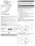
9 Steam connection
Inlet pipes connected to the machine must be equipped with a manual shut-off valve to facilitate
installation and servicing.
The connection hose must be of type ISO/1307- 1983 or equivalent.
Connection size at filter:DN 15 (BSP 1/2").
Demount the top panel (A).
Demount the casing (B.
27
A
B
fig.6600
Mount the nipple to the steam valve.
Mount the steam valve on the machine.
Mount nipple, strainer and elbow. Note the direction of the strainer.
Mount steam hose to the elbow.
Check that there are no sharp angles or bends on the connected steam hose.
28
fig.5862A
Steam connection
45
Mount the hose with wires between steam valve and machine.
Connect wires in the steam valve.
Connect ground cable to the terminal ground connection.
Connect the ”HEAT” cable connector to the ”HEAT” terminal on the I/O board.
29
”HEAT”
fig.6604
Steam pressure required:
• minimum: 50 kPa (0.5 kp/cm2)
• maximum: 800 kPa (8 kp/cm2)
• recommended: 600 kPa (6 kp/cm2)
Note!
A steam heated machine is only intended to use clean steam.
46
Selection of language
10 Selection of language
When the installation is complete and the power is connected for the first time you will be forced to
select language for the machine. Select language from the list on the display.
This will be the language that all display messages, program names etc will be presented in.
For more information about changing language and other functions please refer to the programming
and configuration manual.
Function check
47
11 Function check
May only be carried out by qualified personnel.
A function check must be made when the installation is finished and before the machine can be
ready to be used.
Open the manual water valves.
Add detergent in the compartment for main wash and start a program.
• Check that the drum rotates normally and that there are no unusual noises.
• Check that there are no leaks in water supply/drain connections.
• Check that water passes through the detergent container.
• Check that the door cannot be opened during a program.
Ready to use
If all tests are OK the machine is now ready to be used.
If some of the tests failed, or deficiencies or errors are detected, please contact your local service
organisation or dealer.
lastpage
Electrolux Laundry Systems Sweden AB
341 80 Ljungby, Sweden
www.electrolux.com/laundrysystems
Share more of our thinking at www.electrolux.com