1
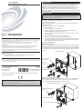
Crestron C2N-SDC
Shade and Drape Controller, 120 Vac
Operations & Installation Guide
DESCRIPTION
The Crestron® C2N-SDC is a 2-channel shade and drape controller designed to provide a
convenient and cost-effective solution for controlling a variety of motorized window
treatments as well as motorized doors, sunroofs, lifts, and projection screens. The
C2N-SDC is a Cresnet® device with two independently controlled 120 Vac outputs. Each
output provides up and down or open and close control of a conventional three-wire
bidirectional motor. Built-in timing and interlock logic make it easy to program the C2N-SDC
for failsafe operation.
INSTALLATION
NOTE: Before using the C2N-SDC, ensure the device is using the latest firmware. Check
for the latest firmware for the C2N-SDC at www.crestron.com/firmware. Firmware is
loaded onto the device using Crestron Toolbox™.
Further Inquiries
To locate specific information or resolve questions after reviewing this guide, contact Crestron's True Blue Support at
1-888-CRESTRON [1-888-273-7876] or, for assistance within a particular geographic region, refer to the listing of
Crestron worldwide offices at www.crestron.com/offices.
To post a question about Crestron products, log onto Crestron’s Online Help at www.crestron.com/onlinehelp.
First-time users must establish a user account to fully benefit from all available features.
Future Updates
As Crestron improves functions, adds new features, and extends the capabilities of the C2N-SDC, additional
information may be made available as manual updates. These updates are solely electronic and serve as
intermediary supplements prior to the release of a complete technical documentation revision.
Check the Crestron website periodically for manual update availability and its relevance. Updates are identified as
an “Addendum” in the Download column.
The C2N-SDC can be mounted in a 2-gang electrical box or a 4 inch square (1900)
electrical box. The electrical box must be at least 1 1/2 inches (39 mm).
IMPORTANT SAFEGUARDS
When using electrical equipment, basic safety precautions should always be followed
including the following:
READ AND FOLLOW ALL SAFETY INSTRUCTIONS.
● Do not use outdoors.
● Do not mount near gas or electric heaters.
● Equipment should be mounted in locations and at heights where it will not be
subjected to tampering by unauthorized personnel.
● The use of accessory equipment not recommended by the manufacturer may cause
an unsafe condition.
● Do not use this equipment for other than its intended use.
● All servicing should be performed by qualified service personnel.
● If any Emergency Circuits are fed or controlled from this panel, it must be located
electrically where fed from a UPS, generator, or other guaranteed source of power
during emergency and power outage situations.
SAVE THESE INSTRUCTIONS.
Mounting to a 2-Gang Box
When mounting in a 2-gang electrical box, use the four #06-32 3/8 inch pan head screws,
two #6 washers, and two 1/4 inch ID nylon cable clamps. Mount the 2-gang electrical box
horizontally (with the mounting tabs on the left and right sides of the box) to maintain an
upright orientation of the C2N-SDC. Refer to the following illustration (wiring is not shown
for clarity).
2-Gang Electrical Box
WARNING: To avoid fire, shock, or death, turn off power at circuit breaker or fuse and test that power is off before
wiring!
NOTES: Observe the following points.
• To be installed and/or used in accordance with appropriate electrical codes and regulations.
• This product should be installed by a qualified electrician.
PREPARING AND CONNECTING WIRES
Strip the ends of the wires approximately 1/4 in (6 mm). Use care to avoid nicking the conductors. Twist together
the ends of the wires that share a connection. Apply solder only to the ends of the twisted wires. Avoid tinning too
far up the wires or the end becomes brittle.
(2) 1/4 in ID Nylon
Cable Clamps
(2) #6 Flat
Washers
Crestron Electronics, Inc.
15 Volvo Drive Rockleigh, NJ 07647
Tel: 888.CRESTRON
Fax: 201.767.7576
www.crestron.com
Operations & Installation Guide - DOC. 6316A
(2011633)
11.14
Specifications subject to
change without notice.
(4) 06-32 3/8 in
Pan Head Screws
As of the date of manufacture, the C2N-SDC has been tested and found to comply with
specifications for CE marking.
FCC Compliance Statement
This device complies with Part 15 of the FCC Rules. Operation is subject to the following conditions:
1. This device may not cause harmful interference, and
2. This device must accept any interference received, including interference that may cause undesired operation.
Mounting to a 4 Inch Square (1900) Box
When mounting the C2N-SDC in a 4 inch square electrical box, use the two 8-32 3/8 inch
pan head screws, two #8 flat washers, and the two 1/4 inch ID nylon cable clamps as
shown in the following illustration (wiring is not shown for clarity).
4 in Square (1900) Electrical Box
(2) 8-32 3/8 in Pan Head
Screws
(2) #8 Flat Washers
(2) 1/4 in ID Nylon Cable Clamps
HARDWARE HOOKUP
OPERATION
Connections for power, Cresnet, and shades or drapes must be made prior to installation.
Power Hookup
AC power is connected to the three pigtail leads as shown in the following illustration.
AC Hookup Connections for the C2N-SDC
The C2N-SDC front panel can be used for local control and Net ID setup. Refer to the
following illustration for details.
C2N-SDC Operation
Grommet
Holes for
Motor Control
Cables
The 3-wire ac pigtail
exits from the back of
the C2N-SDC.
Motor
Controls 1
Motor
Controls 2
Cable secures the
pigtail to the rear of the
C2N-SSDC.
Cresnet
Connectors
3-Wire AC Pigtail Wire Colors
Ground - Green with Yellow Stripe
Hot - Black
Neutral - White
SETUP LED and Push
Button to Set Net ID
Using Crestron Toolbox
Power Indicator LED
(Indicates power received
from Cresnet)
NET Indicator LED
(Indicates unit identified
in program)
TROUBLESHOOTING
AC Wiring to Breaker
NOTE: All wiring must be installed in accordance with all local and national electrical
codes.
Shade or Drape Motor Hookup
Pass the shade or drape motor cable through the nylon cable clamp (supplied, refer to
“Installation”) and through the hole in the front of the C2N-SDC. Connect the shade or
drape motor cable as shown in the following illustration.
C2N-SDC Connections
Common (Neutral)
The following table provides corrective action for possible trouble situations. If further
assistance is required, please contact a Crestron customer service representative.
C2N-SDC Troubleshooting
TROUBLE
The green PWR LED
does not illuminate.
The yellow NET LED
does not illuminate.
Up
Ground
The shade or drape
does not respond.
Down
POSSIBLE CAUSE(S)
CORRECTIVE ACTION
An incorrect power
supply is being used.
Use a Crestron power
supply.
The device is not
receiving power.
Verify that the cables
plugged into the NET ports
are secure.
There is an improper
Net ID on the device or
program.
Verify that the C2N-SDC’s
Net ID matches the Net ID in
the control system program.
There is a loose
network connection.
Verify that the cable plugged
into the NET port is secure.
A fault exists in the ac
wiring.
Check the wiring.
A fault exists with the
shade or drape.
Verify that the shade or drape
upper and lower limits are set
properly. Refer to the shade
or drape manufacturer's
instructions.
Motor Cable
Product warranty can be found at www.crestron.com/warranty.
The specific patents that cover Crestron products are listed at patents.crestron.com.
NOTE: The power wires are not shown in this illustration for clarity.
Crestron, the Crestron logo, Cresnet, and Crestron Toolbox are either trademarks or registered
trademarks of Crestron Electronics, Inc. in the United States and/or other countries. Other trademarks,
registered trademarks, and trade names may be used in this document to refer to either the entities
claiming the marks and names or their products. Crestron disclaims any proprietary interest in the
marks and names of others. Crestron is not responsible for errors in typography or photography.
This document was written by the Technical Publications department at Crestron.
©2014 Crestron Electronics, Inc.