1
Table of Contents
1
2
3
4
General Information .................................................................................................................... 3
Components and Materials of Construction ............................................................................. 3
Regulations and Safety Instructions ......................................................................................... 3
Application and Planning ........................................................................................................... 4
4.1
4.2
4.3
5
Application.......................................................................................................................................... 4
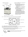
Operation Overview ............................................................................................................................ 4
MVHR installation planning ................................................................................................................. 4
Assembly and Installation .......................................................................................................... 5
5.1
General information: ........................................................................................................................... 5
5.2
Impact noise reduction: ....................................................................................................................... 5
5.3
Connecting the ducting: ...................................................................................................................... 5
5.4
Duct connections: ............................................................................................................................... 6
5.4.1
Left-handed installation duct connections (viewed from the top of the MVHR)............................... 6
5.4.2
Retaining bracket to prevent extraction of the heat exchanger ...................................................... 6
5.5
Installation .......................................................................................................................................... 7
5.5.1
Wall-mounting the MVHR............................................................................................................. 7
5.5.2
Installation of the ducting.............................................................................................................. 7
5.6
Condensate drain ............................................................................................................................... 7
5.7
Typical installation example ................................................................................................................ 7
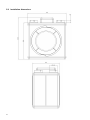
5.8
Installation dimensions........................................................................................................................ 8
6
Technical Data............................................................................................................................. 9
6.1
6.2
6.3
6.4
6.5
6.6
6.7
7
Electrical Wiring Diagrams....................................................................................................... 11
7.1
7.2
7.3
7.4
7.5
8
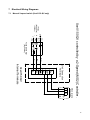
Manual 2-speed switch (Xcell 150 QV only) .......................................................................................11
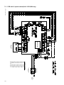
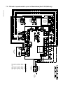
PCB with 3-speed switch (Xcell 150 QVW only) .................................................................................12
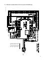
PCB with 3-speed switch & CO2 sensor (Xcell 150 QVW only) ...........................................................13
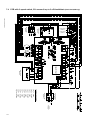
PCB with 3-speed switch, CO2 sensor & up to 3 off Humidistats (Xcell 150 QVW only).......................14
PCB with 3-speed switch & up to 4 off Humidistats (Xcell 150 QVW only)...........................................15
Controller Functions................................................................................................................. 16
8.1
8.2
8.3
8.4
8.5
8.6
9
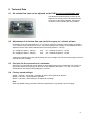
Air volume flow rates can be adjusted on the PCB by service technicians only: ................................... 9
Adjustment of air volume flow rate (m3/h) for supply air / exhaust air fans: ........................................... 9
Port pins for the connection of a voltmeter:.......................................................................................... 9
Factory speed settings: ....................................................................................................................... 9
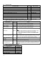
Technical data: ..................................................................................................................................10
Applied Energy accessories for manual or automatic operation: .........................................................10
Applied Energy spares available: .......................................................................................................10
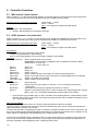
MS2 manual 2-speed switch ..............................................................................................................16
Q3SP automatic 3-speed switch ........................................................................................................16
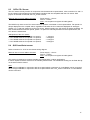
QCO2 CO2 Sensor .............................................................................................................................17
QHS humidistat sensor ......................................................................................................................17
Automatic defrost (anti-icing protection) .............................................................................................18
Fan fault monitoring ...........................................................................................................................18
Maintenance .............................................................................................................................. 19
9.1
9.2
9.3
9.4
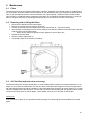
Filters ................................................................................................................................................19
Removing and re-fitting the filters.......................................................................................................19
Air Filter Box (optional extra accessory) .............................................................................................19
Cleaning the heat exchanger .............................................................................................................20
10 Malfunctions.............................................................................................................................. 20
10.1
10.2
Fault locating table.............................................................................................................................20
Installation of replacement fans..........................................................................................................21
11 Customer Notes (to record details of filter / recuperator cleaning etc.)................................ 23
Maintenance Log ............................................................................................................................. 26
GUARANTEE.................................................................................................................................... 28
2