1
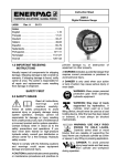
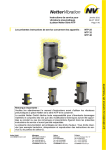
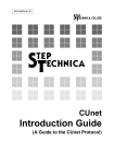
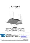
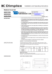
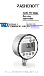
DG25 I&M Rev. #2_I&M006 10197 7/30/12 11:41 AM Page 1 Installation and Operating Instructions for General Purpose Digital Pressure Gauge Type DG25 Software Version 1.00.00 Tel: +44 (0)191 490 1547 Ashcroft Inc. 250 East Main Street, Stratford, CT 06614 USA +44 (0)191 477 5371 Tel: 203-378-8281, Fax: Fax: 203-385-0402 www.ashcroft.com All sales subject to Email: [email protected] terms and conditions of sale. © 2012 Ashcroft Inc. I&M006-10197 DG25 1 Website: www.heattracing.co.uk www.thorneanderrick.co.uk DG25 I&M Rev. #2_I&M006 10197 7/30/12 11:41 AM Page 2 2 DG25 I&M Rev. #2_I&M006 10197 7/30/12 11:41 AM Page 3 WARNING! READ BEFORE INSTALLATION 1. GENERAL: A failure resulting in injury or damage may be caused by excessive overpressure, excessive vibration or pressure pulsation, excessive instrument temperature, corrosion of the pressure containing parts, or other misuse. Consult Ashcroft Inc. Stratford, Connecticut, USA before installing if there are any questions or concerns. (if possible), pumps should be brought up to power slowly, and valves opened slowly. To avoid damage from both fluid hammer and surges, a surge chamber should be installed. Symptoms of fluid hammer and surge’s damaging effects: • Digital Gauge exhibits large zero offset. • Digital Gauge pressure display remains constant regardless of pressure 2. OVERPRESSURE: Pressure spikes in excess of the rated overpressure capability of the gauge may cause irreversible electrical and/or mechanical damage to the pressure measuring and containing elements. Fluid hammer and surges can destroy any pressure transducer and must always be avoided. A pressure snubber should be installed to eliminate the damaging hammer effects. Fluid hammer occurs when a liquid flow is suddenly stopped, as with quick closing solenoid valves. Surges occur when flow is suddenly begun, as when a pump is turned on at full power or a valve is quickly opened. • Error code is displayed on screen. FREEZING: Prohibit freezing of media in pressure port. Unit should be drained. (Mount in vertical position to prevent possible overpressure damage from frozen media.) 3. INSTALLATION: This procedure requires the use of a 11⁄16˝ (27mm) hex wrench for tightening the instrument to the process connection. Apply Teflon tape or a suitable sealing compound to NPT threads of the gauge. Take using the wrench, tighten 1 turn beyond hand-tight or until a leak-proof seal has been achieved. PRESSURE SURGES: Surges are particularly damaging to pressure gauges if the pipe is originally empty. To avoid pressure surges, fluid lines should remain full Caution: Tightening the product by grasping or putting a tool on the plastic housing can cause permanent damage to the product. 3 DG25 I&M Rev. #2_I&M006 10197 7/30/12 11:41 AM Page 4 4. GENERAL INFORMATION: Keypad: Power On-Off / Enter | Tare Zero / Up Arrow / Tare ZERO Menu Selection / Down / Backlight Arrow MENU ➟ ➟ Key presses are short less than 0.5 seconds or long greater than 0.5 seconds 4 DG25 I&M Rev. #2_I&M006 10197 7/30/12 11:41 AM Page 5 LCD DISPLAY: LCD functions: 5 numerical digits for pressure display. 20 segment pressure range bar graph – each segment equals 5% of range. Sleep and Backlight Timer symbols. Maximum / Minimum Pressure and Tare icons. 5 character alpha-numeric digit display. 4 segment battery life indicator. � Negative pressure indicator. � 5 DG25 I&M Rev. #2_I&M006 10197 7/30/12 11:41 AM Page 6 Note: Key presses designated as short (less than 0.5 sec) are indicated by “➟” ICON ZERO Press ➟. Upon release, the numeric display momentarily disappears and “ZERO” shows in alpha display, then returns to measurement mode. The pressure should now read 0. Zero value is stored in memory. Zero Function: Key presses designated as long (greater than 0.5 sec.) are indicated by “➟” ICON | ➟key to turn instrument ON / Press OFF. When initially turned ON, the display will momentarily show all LCD segments lit, product version and full scale range; the unit will then proceed automatically to the Measurement Mode. Turn the Gauge ON/OFF Note 1: A display message of “RLOCK” indicates that zero is more than ±5% from factory calibration. Zeroing is not possible. Note 2: A message of “ZLOCK” indicates that zero lock function is activated. 6 DG25 I&M Rev. #2_I&M006 10197 7/30/12 11:41 AM Page 7 Tare Function: Programming: Subtracts current pressure value from value displayed in Measurement mode. To enter menu mode MENU 1. Press ➟and release to proceed to programming mode. In Measurement mode, apply desired pressure ZERO press ➟, to enable the tare function. The display will quickly flash “TARE”, then the “TARE” icon will be displayed and the pressure reading will blink. The unit should now read 0. ZERO Press ➟ the TARE key ICON again to disable the function. The display will quickly flash “T OFF”, then the “TARE” icon will disappear and the pressure reading will no longer be blinking. The unit will now return to measurement mode. 2. Press , ➟, to scroll through programmable menu options. 3. When desired option is reached press | ➟ to access that parameter. 4. If at any time you choose to EXIT the menu mode (or sub-menu mode) hold MENU ➟. Your work will not be saved. Programmable Parameters: 1. In Menu mode, press , ➟, to | ➟. scroll to “UNITS”, press Units of Measure: 2. Choose engineering units by scrolling , ➟, until desired unit is displayed, “PSI, BAR, kg/cm, kPa, mPa, FtH2O, InHg, cmHG, mmHg, customer defined units (CUSTU)”. | ➟ to select units and return to 3. Press Measurement Mode. Note: Custom units programming, see page 8. 7 DG25 I&M Rev. #2_I&M006 10197 7/30/12 11:41 AM Page 8 Once the desired value is displayed, press | ➟ button to lock it in place. Now the the next digit to the right will begin blinking. Repeat this procedure for all 5 digits. When | ➟ is pressed and released with the the fifth digit flashing, the gauge will briefly display “DONE” then return to measurement mode and display “CUSTU” along with the numeric readings to signify that the feature is use. Custom Units of Measure Allows a user to define a custom unit of measure, user must enter the full scale value of the desired reading, which can be done as follows. 1) In Menu Mode press , ➟ select | ➟. “CUSTU” press 2) Select decimal point location: The alphanumeric display shall show “SELDP” The first screen to appear will show all digits lit up as “5” and the rightmost decimal point will blink (5 5 5 5.5) unless the custom units feature had been used previously. If it had been used, the digits and decimal point position shall correspond to the last values set. Use the , ➟ keys to move the decimal point to the left or the right. Once the decimal point is in the desired position, | ➟ to lock it in place. When the press key is released the display reads “DIGIT”. The user can optionally exit at any point before the enter key is pressed with MENU ➟. If the user exits the menu by a MENU ➟ before completing step 2 or there is a menu timeout, then whatever the user entered will be lost. Note: The custom units feature is not available with compound pressure ranges. Note: The bar graph uses the factory default setting when custom units are used. 3) Choose full scale value: Note: The magnitude of the value entered when using the custom units feature can significantly increase the noise on the display, which can affect the zero and tare functions as well as the stability of the pressure reading displayed. If required, consult factory for recommended limitations on full scale input. The alpha numeric display shall show “DIGIT”. The next screen will continue to show all digits as “5”, with the leftmost digit blinking and the decimal point fixed in the previously chosen position. However, if the custom units feature has been used previously, then the digits shall correspond to the last value. The decimal point remains at the location chosen in step 1. Press , ➟ to change the value of the digit between 0-9. 8 DG25 I&M Rev. #2_I&M006 10197 7/30/12 11:41 AM Page 9 Maximum / Minimum: Timer: Displays maximum / minimum pressure values; this is initiated upon powering the unit or since the values were cleared. Controls how long the gauge will remain pow| is pressed. ered ON once the Power key 1. When in menu mode press , ➟ to scroll until “TIMER” is displayed. 1. When in menu mode press , ➟ to scroll to ‘Max’ (maximum display); this is indicated in small font to the left of the display’s unit of measure. | ➟. 2. Press 3. Then, press , ➟ to scroll through values. “NONE” designates that the gauge will remain ON until the | is pressed a second power key time. Any other value (1 min [default] / 5 min / 20 min), other than “NONE”, will designate the duration of time this function will be in effect. 2. To clear both Min and Max values, press ZERO and hold ➟. 3. Release of this key will leave you in Menu mode. Use , ➟ to continue scrolling through the menu MENU options, OR hold, ➟ to return to measurement mode. | ➟ to select desired value; 4. Press timer icon will be shown on the display and the unit will display “DONE” then return to Measurement Mode. Note: Clearing Minimum / Maximum values will reflect a blank display except for the associated Min. / Max. icon and battery indicator. Feature: Timer icon will flash 10 seconds prior to gauge shut down. Note: The following actions will also clear min/max values. Power off, zero gauge function, tare function, field calibration function, units programming, update rate, or reset. 9 DG25 I&M Rev. #2_I&M006 10197 7/30/12 11:41 AM Page 10 Light: Update: Determines how long the back light will remain ON after any key is pressed in Measurement or Menu Modes (Note: The timer is reset with any key being pressed.) Utilized to select the rate at which the displayed pressure value is updated on the screen. This function is used when rapid changes in pressure cause “flutter” in the display values; longer intervals will reduce the update rate and “average” the readings on such applications. 1. While in Menu mode, press until “LIGHT” is displayed. , ➟ | ➟ for timer value to appear; 2. Press “ON” refers to the back light remaining ON at all times unit is powered ON, “PRESS” designates that the back light is switched on / off by briefly pressing MENU the backlight ➟ whereas, “OFF” indicates the back light will never be illuminated. Selecting time values, “1 MIN” (default), “5 MIN”, “20 MIN”, will activate the backlight symbol on the LCD display for the designated minutes. 1. In Menu mode, press “UPDAT” appears. | 2. Press , ➟until ➟ to select. 3. Press , ➟ to select values for “1 SEC” (default), “500 MSEC”, or “250 MSEC”. | ➟ to select value (display will 4. Press briefly show “DONE”) and return to Measurement Mode. | ➟ to select back light time 3. Press (display will briefly show “DONE”) and return to Measurement Mode. Note: Changing value to anything other than 1 sec may cause a slight zero offset, and it is recommended that the gauge be fully vented and re-zeroed before taking accurate readings. Also, battery life will be reduced by use of an update rate faster than 1 SEC. Note: In “PRESS” mode; factory has set 1 hour timer to save battery. Feature: Back light indicator will blink 10 seconds prior to light shut off. 10 DG25 I&M Rev. #2_I&M006 10197 7/30/12 11:41 AM Page 11 Z-Lock: Re-Calibration: Utilized to prevent inadvertent re-zeroing of the instrument. Provides the user the ability to field calibrate the product. Original factory calibration is permanently retained in memory and can be recalled at any time. 1. In Menu mode, press , ➟until “ZLOCK” appears. 1. In menu mode press , ➟until “RECAL” appears; proceed to press | ➟. ➟to select. , ➟to select “L ON” or “L | 2. Press 3. Press OFF” (default). | ➟ to select value (display 4. Press will briefly show “DONE”) and return to Measurement Mode. 2. Display will indicate “FACT” (factory) “FIELD” or “NEW’ press , ➟ to scroll. | ➟ while “FACT” (factory) is 3. Pressing displayed will restore values of factory calibration. Note: If Z-Lock is activated, the gauge will display “ZLOCK” if zero is attempted. | ➟ when “FIELD” is dis 4. Pressing played will restore values from latest field calibration. | ➟ when “NEW” 5. Pressing “Enter” key appears will enter the recalibrate mode. | ➟; 6. When “NEW” is displayed, press upon release, the display will flash “OK/ APPLY/ REF/ PSI/ THEN/ PRESS/ ENTER/ TO/ START/ OR/ OTHER/ TO/ ABORT”. Numeric display will read .00000. Vent sensor to atmospheric pressure, press | ➟ display will show “WAIT” and count down from 6 seconds then briefly display CAL then automaticly go to next step. 7. Display flashes “APPLY/ REF/ PSI/ THEN/ PRESS/ ENTER/ TO/ START/ OR/ OTHER/ TO/ ABORT”; apply the full scale pressure in units of psi indicated in numeric display | ➟ display will show to gauge. Press “WAIT” and count down from 6 seconds then briefly display CAL then automatically go to next step. 11 DG25 I&M Rev. #2_I&M006 10197 7/30/12 11:41 AM Page 12 8. Display flashes “APPLY/ REF/ PSI/ THEN/ PRESS/ ENTER/ TO/ START/ OR/ OTHER/ TO/ ABORT”; apply the pressure indicated in numeric display to gauge and press | ➟ display will show “WAIT” and count down from 6 seconds then briefly display GOOD then exit into measurement mode, or Graph: Provides the user the ability to modify pressure values dictating the minimum / maximum indications over the 20 segment bar graph. 1. In menu mode press , ➟, | ➟. until “GRAPH” appears; press 2. Display will indicate “CGOFF” (custom graph off) [default], “CG ON” (custom graph on), or “NEWCG” (new custom graph) press , ➟ to scroll. 9. COMPOUND RANGE GAUGES ONLY REQUIRE ONE ADDITIONAL CALIBRATION POINT NEAR VACUUM 3. To recall the last custom graph entered when “CG ON” is displayed press | ➟. Display will briefly show “DONE” and return to Measurement Mode. 10. Display flashes “APPLY/ REF/ PSI/ THEN/ PRESS/ ENTER/ TO/ START/ OR/ OTHER/ TO/ ABORT”; apply near vacuum of –14.000 psi as indicated in numeric | ➟, display to gauge and press display will show “WAIT” and count down from 6 seconds then briefly display “GOOD” then exit into Measurement Mode. 4. To reset bar graph to full scale range; | when “CGOFF” is displayed press ➟ Display will briefly show “DONE”, and return to Measurement Mode. Note: Recalibration is allowed only if test parameters are within ±7%. If outside this window, the display will indicate “CAL FAIL / INPUT PRES TOO LOW (HIGH) / PRESS ENTER TO RETRY / PRESS OTHER TO ABORT”. 5 To enter a new custom bar graph; when | ➟. “NEWCG” is displayed press Note: “FIELD” option appears only if gauge has been successfully field recalibrated. 12 DG25 I&M Rev. #2_I&M006 10197 7/30/12 11:41 AM Page 13 Reset: 6. To program minimum graph percentage, the display will indicate 0 0 with the right digit flashing, the bottom most segment of the bar graph will flash, and the display will read “PCTFS” (percent full scale). Press , ➟ to scroll to a num| ➟ to select that num ber 0-9. Press ber. The left digit will now begin to flash. Press , ➟. to scroll to a | ➟. to select that number 0-9. number. The 2 digit number entered represents the percentage of full scale to be used as the low end of the graph (0-99%). Returns the product to the factory default values.Preserves field calibration. Factory calibration can be restored in the “RECAL” menu. 1. In menu mode , ➟until “RESET” | ➟. appears on display’s lower line; Factory defaults pertain to units, timer, back light, update rate, zero lock. Display will indicate “DONE” then gauge will switch to “OFF” condition. 7. To program maximum percentage of full scale the display will indicate 1 0 0 with the right digit flashing, the upper most segment of the graph will flash, and the display will read PCTFS (percent full scale). Press , ➟. to scroll to | ➟ to select a number 0-9. Press that number. The left 2 digits will now begin to flash. Press , ➟to | ➟ scroll to a number 0-10. Press to select that number. The number entered represents the percentage of full scale to be used as the high end of the graph. Note: 100 is the highest and only possible 3 digit number. If the low number is equal to or larger than the high number, the unit will flash “REJCT” and it will exit back into the “GRAPH” sub-menu. Note: Custom graph function is not available on vacuum and compound ranges. Note: A display message “ULOCK” indicates that custom units are being used and bar graph minimum and maximum are set to the factory defaults 13 DG25 I&M Rev. #2_I&M006 10197 7/30/12 11:41 AM Page 14 Changing Batteries: Grip knurled back cover and rotate counterclockwise until the ‘unlock’ icon is in alignment with the arrow – this is on the housing at the base of the pressure connection. WARNING: Misuse may cause injury or damage. Refer to ASME B40.100 Remove cover by pulling straight back and replace AA alkaline batteries accordingly; ensure that the batteries are in the proper polarity position. For reattachment of cover, align the ‘unlock’ icon with the arrow, push cover straight in then turn clockwise until the arrow is in alignment with the ‘Lock’ icon. Note: Reinstallation of the back cover may cause the unit to read negative pressure. This is a temporary issue as the internal case pressure will be relieved by the case vent and equalize with atmospheric pressure (90% of the offset will equalize within 1 minute, the remaining 10% may take up to 5 minutes). WARN may ca ING: Misus e us damag e injury or e. ASME Refer to B40.100 14 DG25 I&M Rev. #2_I&M006 10197 7/30/12 11:41 AM Page 15 Dimensions: Pressure Range: Proof Pressure: Vac-2000psi 200% % of Span 3000-5000psi: 150% 7500-25,000psi: 120% Burst Pressure: Vac-2000psi: 800% % of Span 3000-5000psi: 500% 7500-25,000psi: 300% 69.36mm Ø2.73in Environmental Specifications: Temperature Storage: Batteries removed: –20°C to 80°C (–4°F to 176°F) Batteries installed: –20°C to 60°C (–4°F to 140°F) Ambient Operating: –20°C to 60°C (–4°F to 140°F) Process Media: –20°C to 80°C (–4°F to 176°F) 50.5mm 1.99in 67mm 2.64in 1/4 NPT Male 27mm 1.063in Hex 40.9mm 1.61in Agency Approvals: CE EN 61326 (1998); CE EN 61326 Annex A (Heavy Industrial) UL/cUL- 61010-1 (pending) RoHS compliant 67.6mm Ø 2.66in 17.5mm .69in Tel: +44 (0)191 490 1547 Fax: +44 (0)191 477 5371 Email: [email protected] Website: www.heattracing.co.uk www.thorneanderrick.co.uk 15