1
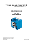
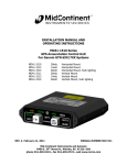
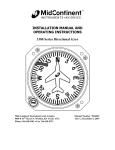
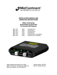
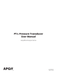
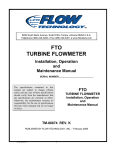
INSTALLATION MANUAL AND
OPERATING INSTRUCTIONS
MD15-( ) Series
Altimeter
REV. C October 15, 2010
MANUAL NUMBER 9017061
MID-CONTINENT INSTRUMENT CO., INC.
9400 E. 34th Street N., Wichita, KS 67226 USA
phone 316-630-0101 • fax 316-630-0723 • web www.mcico.com
FOREWORD
This manual provides information intended for use by persons who, in accordance with current regulatory
requirements, are qualified to install this equipment. If further information is required, please contact:
Mid-Continent Instruments
Attn: Customer Service Dept.
9400 E. 34th Street N.
Wichita, KS 67226 USA
Phone 316-630-0101 Fax 316-630-0723
We welcome your comments concerning this manual. Although every effort has been made to keep it free of
errors, some may occur. When reporting a specific problem, please describe it briefly and include the manual
part number, the paragraph/figure/table number, and the page number. Send your comments to:
Mid-Continent Instruments
Attn: Technical Publications
9400 E. 34th Street N.
Wichita, KS 67226 USA
Phone 316-630-0101, Fax 316-630-0723
[email protected]
www.mcico.com
© Copyright 2010
Mid-Continent Instrument Co., Inc.
REV. C October 15, 2010
2
Manual Number 9017061
REVISION DETAIL
Rev.
A
B
Date
06/25/10
08/12/10
Approved
CJM/BAW
BAW/CJM
C
10/15/10
MKN/CJM
REV. C October 15, 2010
Detail
Initial release
Updated Table 1.2 with Humidity and Magnetic Effect info. Added
detail to Section 4 Conformance table.
Changed 0.890/0.885 from Ø2.625BC hole to knob hole cutout in
Figure 3.2.
3
Manual Number 9017061
TABLE OF CONTENTS
SECTION 1
1.1
1.2
INTRODUCTION
TECHNICAL SPECIFICATIONS
1.2.1 PHYSICAL ATTRIBUTES
1.2.2 QUALIFICATIONS
SECTION 2
2.1
2.2
2.3
2.4
INSTALLATION PROCEDURE
GENERAL INFORMATION
UNPACKING AND INSPECTING
INSTALLATION
LIMITATIONS
SECTION 3
3.1
GENERAL DESCRIPTION
OPERATION
MINIMUM PERFORMANCE REQUIREMENTS
3.1.1 SCALE ERROR
3.1.2 HYSTERESIS
3.1.3 AFTER EFFECT
3.1.4 FRICTION
3.1.5 CASE LEAK
3.1.6 POSITION ERROR
3.1.7 BAROMETRIC SCALE ERROR
SECTION 4
4.1
4.2
NUMBER
1.1
1.2
1.3
3.1
3.2
3.3
CONFORMANCE
CONTINUED AIRWORTHINESS STATEMENT
ENVIRONMENTAL QUALIFICATION STATEMENT
LIST OF TABLES AND FIGURES
PHYSICAL ATTRIBUTES TABLE
QUALIFICATION TABLE
CONFIGURATION DATA
MD15 OUTLINE DRAWING
PANEL CUTOUT DIMENSIONS
MD15 REAR VIEW
REV. C October 15, 2010
4
Manual Number 9017061
SECTION 1
1.1
GENERAL DESCRIPTION
INTRODUCTION
The model MD15-( ) series two-inch Altimeter is a pressure actuated, sensitive altimeter built to meet or exceed
SAE AS392C standards as per FAA TSO-C10b.
Features include a three-pointer indication (100 feet, 1000 feet, and 10,000 feet) and an inset dial displaying
the manual knob adjustment for barometric pressure correction. Internally, a compensation mechanism
maintains accuracy throughout the rated temperature range.
1.2
TECHNICAL SPECIFICATIONS
1.2.1
PHYSICAL ATTRIBUTES
Table 1.1
Characteristics:
Weight:
Dimensions:
Colors:
0.8 pounds
See outline drawing; Figure 3.1
Dial background is black #37038 per FED-STD-595
Markings are white #37875 per FED-STD-595
Pointers are white with black hub and counterweight
Case and bezel are black
HEA (anti-reflective) coated per MIL-C-14806
9/16-18 UNJF-3B per MS33649-06
Rear mount, see panel cutout; Figure 3.2
Field replaceable light tray available for 5, 14, & 28VDC input
with incandescent bulbs or white LEDs
Cover Glass:
Connection:
Mounting:
Lighting:
1.2.2
QUALIFICATIONS
Specifications:
Qualification:
Altitude, Valid
Altitude, Survivable
Operating Temperature:
Storage Temperature:
Humidity:
Magnetic Effect:
1.3
Table 1.2
FAA TSO-C10b
-1,000 ft to (rated range); see Section 1.3
-1,000 ft to +50,000 ft
-30°C to +50°C (-22°F to +122°F)
-65°C to +70°C (-85°F to +158°F)
95% @ +70°C and 100% @ +38°C
no effect at 0.0m from unit; DO-160F, Section 15, Category Y
CONFIGURATION DATA
Part Number
MD15-211
MD15-212
MD15-221
MD15-222
MD15-311
MD15-312
MD15-321
MD15-322
Table 1.3
Range (ft) Barometer
20,000
Millibars
20,000
Millibars
20,000
In Hg
20,000
In Hg
35,000
Millibars
35,000
Millibars
35,000
In Hg
35,000
In Hg
Knob
Right
Left
Right
Left
Right
Left
Right
Left
** other versions or options may be available on request **
REV. C October 15, 2010
5
Manual Number 9017061
SECTION 2
2.1
INSTALLATION PROCEDURE
GENERAL INFORMATION
This section contains mounting dimensions and other information pertaining to the installation of the MD15
Altimeter.
2.2
UNPACKING AND INSPECTING EQUIPMENT
When unpacking this equipment, make a visual inspection for evidence of any damage that may have incurred
during shipment. The following parts should be included:
a. Altimeter –
b. Installation Manual –
Optional equipment available:
a. Light tray (LED) –
b. Light tray (incandescent) –
c.
Tinnerman nuts (3) –
Equipment not provided:
a. Mounting Hardware –
b. Air fitting –
2.3
MCI P/N MD15-( )
MCI P/N 9017061
MCI P/N MD31, -4, -6 (28, 14, 5V)
MCI P/N 6015358-2 (28V)
MCI P/N 6015010-2 (14V)
MCI P/N 6018634-2 (5V)
MCI P/N 6013031
three (3) #6-32 screws
#6 lock washers (optional)
per aircraft mfg. requirements;
9/16-18 x 1/8-inch tube fitting available
(MCI P/N NY-400-1-6ST)
INSTALLATION
Install the MD15 Altimeter within the aircraft in accordance with the aircraft manufacturer’s instructions and the
following steps:
A. Ensure the available instrument panel cutout meets the requirements of the indicator. See Fig 3.2
B. Secure the indicator to the instrument panel using the screw sizes called out in the Section 2.2. Length
of screws will be determined by aircraft instrument panel thickness. The aircraft manufacturer or the
installation facility is responsible for supplying appropriate hardware.
C. Connect static line tube to the pressure port on the back of the altimeter.
CAUTION: INSTALL FITTING IN PORT WITH NO MORE THAN 100 IN-LBS OF TORQUE. IF TORQUE
IS NOT SUFFICIENT TO MAINTAIN A SEAL THREAD SEALANT MUST BE USED.
D. For units with light tray, connect wires to the appropriate voltage as marked on the light tray.
2.4
LIMITATIONS
The conditions and tests for TSO approval of this article are minimum performance standards. Those installing
this article, on or in a specific type or class of aircraft, must determine that the aircraft installation conditions
are within the TSO standards. TSO articles must have separate approval for installation in an aircraft. The article
may be installed only according to 14 CFR part 43 or the applicable airworthiness requirements.
REV. C October 15, 2010
6
Manual Number 9017061
2.38
2.37
45° TYP
(0.125)
(3.777)
(0.610)
1.252
1.232
Ø2.255
2.235
(Ø2.245)
1.198
1.178
3X Ø0.171
0.168 on Ø2.625 BC
(0.517)
0.60 MAX
FIGURE 3.1
MD15 OUTLINE DRAWING
3X 0.172
0.168
ON Ø2.625 BC
3X 46°
44°
0.890
0.885
Ø2.280
2.265
Ø0.385
0.375
0.890
0.885
(-XX1, right-hand knob version)
(-XX2, left-hand knob version)
FIGURE 3.2
PANEL CUTOUT DIMENSIONS
REV. C October 15, 2010
7
Manual Number 9017061
STATIC PORT
9/16-18 UNJF-3B
PER MS33649-06
(0.515)
(0.515)
(-XX1, right-hand knob version)
(-XX2, left-hand knob version)
FIGURE 3.3
MD15 REAR VIEW
SECTION 3
3.1
OPERATION
MINIMUM PERFORMANCE REQUIREMENTS
The MD15 Altimeter shall meet these minimum performance requirements under standard test conditions.
3.1.1
SCALE ERROR
With the barometric scale pressure set at 29.92 inches of mercury (1013 millibars), the altimeter
shall be subjected successively to equivalent pressures from -1,000 ft to the rated altitude of the
instrument at the increments established by Table 3.1. The reduction in pressure shall not exceed
20,000 feet per minute to within 2,000 feet of the test point. The test point shall be approached
at a rate compatible with the test equipment. The instrument shall remain at each test point for
at least one minute but not more than ten minutes before a reading is taken. The error at all test
points shall not exceed the tolerances stated in Table 3.1.
3.1.2
HYSTERESIS
The hysteresis test requirement shall be verified within 15 minutes of reaching the upper limit of
the Scale Error test as described in Section 3.1.1. Pressure shall be increased at a rate simulating
a descent in altitude between 5,000 and 20,000 feet per minute until within 3,000 feet of half
(50%) of the instrument’s rated maximum operating altitude (per 14 CFR Part 43, Appendix E).
Then the test point shall be approached at approximately 3,000 feet per minute. Within 10
seconds after the pressure has been stabilized at the test point, the instrument indication shall be
within 100 ft of the original scale error reading. The altimeter shall be kept at this pressure for at
least 5 minutes, but not more than 15 minutes, before the reading is taken. After the reading has
been taken, the pressure shall be further increased at the above rate until the pressure reaches a
corresponding altitude of 40% of the instrument’s rated maximum operating altitude. The
instrument shall remain at this pressure for at least one minute, but not more than 10 minutes,
before the test reading is taken. After the reading has been taken, the pressure shall be further
increased at the above rate until atmospheric pressure is reached. The reading of the instrument
at either of the two test points shall not differ from the instrument reading taken at an equivalent
altitude recorded during the Scale Error test by more than 75 feet.
REV. C October 15, 2010
8
Manual Number 9017061
3.1.3
AFTER EFFECT
Not more than five minutes after the completion of the hysteresis test, the pointers shall have
returned to their original reading, corrected for any change in atmospheric pressure, to within 30
feet.
3.1.4
FRICTION
The altimeter shall be subjected to a steady rate of decreasing pressure equivalent to about 750
feet per minute. The change in reading of the pointer before and after the application of vibration
shall be recorded at the values indicated and within the tolerance as listed in Table 3.1.
Note: Where TSO prescribe altitude values for Friction test points do not match test points in the
Scale Error test, test points before and after the target value have been selected for this test.
(for example: where 5000 ft is called for, test points are taken at 4000 and 6000 instead, to
match the Scale Error test) This method exceeds the TSO requirement.
3.1.5
CASE LEAK
With an equivalent pressure of 18,000 feet applied, the resultant leakage shall not cause the
indicator to deviate more than 100 feet within one minute.
3.1.6
POSITION ERROR
With atmospheric pressure applied to the instrument, the difference between pointer indication when
the instrument is in normal operating position and when it is in any other position shall not exceed 20
feet.
3.1.7
BAROMETRIC SCALE ERROR
With ambient pressure constant, the barometric pressure scale shall be adjusted to each of the
values as listed in Table 3.2 and cause the instrument to indicate the corresponding altitude
within a tolerance of ±25 feet.
REV. C October 15, 2010
9
Manual Number 9017061
Table 3.1
Scale Error and Friction Error
Altitude
(feet)
-1,000
Equivalent Pressure
(inches of mercury)
31.018
Scale Error
Tolerance ±
(feet)
20
Friction Error
Tolerance ±
(feet)
---
0
29.921
20
---
500
29.385
20
---
1,000
28.856
20
70
1,500
28.335
25
---
2,000
27.821
30
70
3,000
26.817
30
70
4,000
25.842
35
70
6,000
23.978
40
70
8,000
22.225
60
---
10,000
20.577
80
80
12,000
19.029
90
---
14,000
17.577
100
80
16,000
16.216
110
90
18,000
14.942
120
---
20,000
13.750
130
100
22,000
12.636
140
---
25,000
11.104
155
120
30,000
8.885
180
140
35,000
7.041
205
160
--- = no friction error reading required at this test point
Table 3.2
Barometric Scale Error
Barometric Scale Reading
REV. C October 15, 2010
MB
IN HG
Indication (feet)
951.6
28.10
-1,727
965.1
28.50
-1,340
982.0
29.00
-863
999.0
29.50
-392
1013.2
29.92
0
1032.8
30.50
+531
1046.4
30.90
+893
1049.4
30.99
+974
10
Manual Number 9017061
SECTION 4
4.1
CONFORMANCE
CONTINUED AIRWORTHINESS STATEMENT
Federal regulations require that within the preceding 2 calendar years an active altimeter instrument be tested and
found to comply with FAR Part 43 Appendix E. If the unit fails to perform to specifications within this period, it
must be removed and serviced by a qualified service facility.
4.2
ENVIRONMENTAL QUALIFICATION STATEMENT
NOMENCLATURE:
Altimeter
MODEL NUMBER:
MD15-( )
MANUFACTURERS SPECIFICATIONS:
QUALIFICATION STANDARD:
CONDITIONS
TSO NUMBER: C10b
Minimum Performance Specifications:
Test Specification (TS) 350, Test Data Sheet (TDS) 350
FAA TSO C10b and SAE AS 392C
TSO
SECTION
3.3.1
DESCRIPTION
Humidity
Vibration
3.3.2
3.3.3
Altitude, Valid
Altitude, Survivable
Magnetic Effect
3.3.4
3.3.4
3.3.5
95% at 70°C and 100% at 38°C
5-50 Hz @ 1.5g, 50-500 Hz @ 0.5g
four complete cycles, no observed resonance
-1,000 ft to (rated range)
-1,000 ft to +50,000 ft
RTCA, DO-160F, Category Y
zero magnetic effect at 0.0m from unit
Temperature
Ground Survival Low
Operating Low
Ground Survival High
Operating High
REV. C October 15, 2010
-65C
-30C
+70C
+50C
11
Manual Number 9017061