1
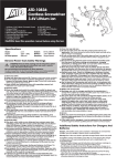
Operating Instructions
TX4 Series Radio Remote Control Transmitter
The TX4 Series Radio Remote Control transmitter is intended for use with matching 1/2/3/4
output receivers.
Installation & Use
These units are intended for use in light industrial, commercial or domestic environments. The
ABS case is protected to IP40 and the tactile switches mounted behind the front panel label
are rated to IP67.
Battery
The transmitter is powered by a 9V PP3 battery that should provide over six months life of
typical usage. The battery compartment is accessed by pressing and then sliding the cover on
the rear of the case. When connecting the battery observe the polarity of the clip and tuck the
wires neatly before replacing the cover. The unit is protected from reverse polarity
connection.
After installing the battery press any transmitter button and check that the transmit LED
indicator lights. If during operation it glows dimly then replace the battery.
Coding
Photo Shows Four Button
Transmitter and Four Relay
Output Receiver
The transmitter utilises a simple encoder that provides adequate security for most applications. There are no special ‘set ups’ required
and coding can be carried out by non-technical personnel. Transmitters can therefore be easily be replaced in the field. In addition
multiple transmitters can be used with one receiver.
When the battery compartment cover is removed an 8 way Dual in Line (DIL) switch is made visible. This sets the ‘code’ that the
transmitter sends and provides 256 differs but it is recommended that for security that the switches are not set All On or All Off.
Using a small scewdriver or similar tool the individual switches can be set On (Up) or Off (Down). Make a note of the settings
selected if multiple transmitters are being set to the same code.
Specifications
Transmitter Type
Frequency
Power Output
Antenna
Buttons
Encoding
Address selection
Transmit Indication
Power
Case
Size
Environment
Front Panel Overlay
Environment
Range
Approvals
Part No
FM/FSK
433.920 MHz +/- 50KHz
< +10dBm
Integrated internal PCB loop
1/2/3/4 option. Momentary positive ‘click’ action
8 bit address (256 differs), 4 bit data. Holtek HT-12 compatible
Internal DIL switch accessible from battery compartment
Red LED through front panel
9V PP3 battery in battery compartment with clip on cover
Black ABS
100 x 65 x 24mm
Case sealed to IP40 for Industrial use
250 micron Polycarbonate – splash proof – wipe clean. Custom overlays available
Case sealed to IP65 for Industrial use
100 metres typical
When operating on 433MHz the units can be used anywhere within the European Union and are compliant
with the requirements of the RTT&E directive.
Tx4 Series. Customer Options have specific Part Numbers
Disclaimer
nikam electronics has an on going policy to improve the performance and reliability of their products, we therefore reserve the right to
make changes without notice. The information contained in this data sheet is believed to be accurate however we do not assume
any responsibility for errors nor any liability arising from the application or use of any product or circuit described herein. This data
sheet neither states nor implies warranty of any kind, including fitness for any particular application.
Warranty
The transmitter is guaranteed against defective components or workmanship for a period of 12 months from the date of purchase.
The product under warranty will be repaired or replaced free of charge providing that damage or malfunction has not been caused
by incorrect electrical connection, overload, tampering with components, unauthorised repair or modifications, water or chemical
contact, lightening or power surges.
Tx4 Instructions.doc Issue 1.0 Nov-01
1 of 1
Copyright nikam electronics 2001
Page
Operating Instructions
TX4 Series Radio Remote Control Transmitter
nikam electronics
West End
Fairford
Gloucestershire
GL7 4JB
Tel: +44 (0)1285 713862
Web: www.nikamelectronics.co.uk
Tx4 Instructions.doc Issue 1.0 Nov-01
2 of 2
Copyright nikam electronics 2001
Page