1
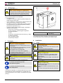
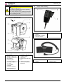
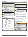
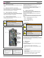
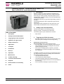
Operating instructions
BA M1201_EN
Issue 11-12
Rotating module – horizontal axis DMHe 100
Max. load 2,000 N, electrically operated
1
Description
Rotating modules are used in assembly and handling processes to transform electrical energy into a rotating movement.
When using the rotating module, component parts can be rotated rationally, quickly and safely and can be assembled ergonomically from all sides.
The strongly reduced worm gear allows high holding torques in
standstill.
The double-bearing drive shaft compensates high axial and
radial forces.
The rotating module is designed for a long service life. The
electronically commutated DC motor is virtually wear-free.
2
Validity of the documentation
This document applies to the following products:
Rotating modules - horizontal axis of data sheet.
The following types or part numbers are concerned:
Table of contents
1
Description
1
2
Validity of the documentation
1
3
Target group of this document
1
4
Symbols and signal words
2
5
Safety instructions
2
6
Application
2
7
Transport
3
8
Installation
3
9
Start up
5
10
Operation
7
11
Maintenance
7
12
Trouble shooting
8
13
Technical characteristics
8
14
Disposal
9
15
EC-Declaration of conformity
9
16
Index
10
•
3
•
6505 0236 E
Target group of this document
Specialists, fitters and set-up men of machines and installations with expert knowledge in electrical engineering.
Qualification of the personnel
Expert knowledge means that the personnel must
• be in the position to read and completely understand technical specifications such as circuit diagrams and productspecific drawing documents,
• have expert knowledge (electric, hydraulic, pneumatic
knowledge, etc.) of function and design of the corresponding components.
An expert is somebody who has due to its professional education and experiences sufficient knowledge and is familiar with
the relevant regulations so that he
• can judge the entrusted works,
• can recognize the possible dangers,
• can take the required measures to eliminate dangers,
• knows the acknowledged standards, rules and guidelines of
the technology.
• has the required knowledge for repair and mounting.
Römheld GmbH • Postfach 1253 • 35317 Laubach • Germany • Tel.: +49 (0)6405 / 89-0 • Fax: +49 (0)6405 / 89-211 • www.roemheld.de
Subject to change without notice! Translation of the original German document
1 / 10
Operating instructions
BA M1201_EN
4
Symbols and signal words
DANGER
Danger of life / heavy health damages
Stands for an imminent danger.
If it is not avoided, death or very severe injuries will
result.
WARNING
Person damage
Stands for a possibly dangerous situation.
If it is not avoided, death or very severe injuries will
result.
CAUTION
Easy injuries / property damage
Stands for a possibly dangerous situation.
If it is not avoided, minor injuries or material damages will result.
Hazardous to the environment
The symbol stands for important information for the
proper handling with materials that are hazardous to
the environment.
Ignoring these notes can lead to heavy damages to
the environment.
5.2
General safety tips
• Avoid collisions and blockades of the drive or the mounting
parts.
These can lead to damages of the internal mechanics.
• Rotating movement of the flange plate and their mounting
parts!
Adjust the speed of the drive as per the developed safety
concept, general guidelines and standards or provide safety
devices, if required!
• If the maximum torque is exceed, the drive will be switched
off.
After reducing the torque, further movement in push-button
mode is possible.
• Exceeding the maximum holding torque or shock loads can
lead to damages in the gearbox.
Loss of self-locking and undesired movement of the workpiece are the consequences.
When fixing additional mounting parts, counterhold the front
block.
• Exceeding the maximum duty cycle can lead to damages of
the electric motor. Pay attention to technical characteristics
• In case of damage or malfunction of the components, these
must be put out of operation immediately!
• The product was developed, tested and built according to
the applicable EMC standards.
In the beginning of the start up it has to be checked whether
there are faults in or interactions between the components
used.
Mandatory sign!
The symbol stands for important information, necessary protection equipment, etc.
Note
This symbol stands for tips for users or especially useful
information. This is no signal word for a dangerous or
harmful situation.
5
Note - qualification of the user
All works may only be effected by qualified personnel
familiar with the handling of hydraulic components.
5.3
Safety instructions
5.1
Basic information
The operating instructions serve for information and avoidance
of dangers when installing the products into the machine as
well as information and references for transport, storage and
maintenance.
Only in strict compliance with these operating instructions,
accidents and property damages can be avoided as well as
trouble-free operation of the products can be guaranteed.
Furthermore, the consideration of the operating instructions will
result in:
• reduced down times and repair costs,
• increased service life of the products.
Note
These operating instructions are not a replacement for
the operating instructions of the entire machine.
Personal protective equipment
For works at and with the product,
wear protective gloves!
For works at and with the product,
wear safety shoes!
6
Application
6.1
Intended use
Rotating modules are designed for universal use in assembly
and handling processes in the industry.
They are used for industrial applications in order to rotate
workpieces rationally, quickly and safely.
Furthermore the following are possible uses:
• Max. forces and / or torques only with the values indicated
below technical characteristics.
• Max. torques at the hand lever only with the values indicated below technical characteristics.
• Use only within closed, low-dust rooms
• Use within the capacity indicated in the technical characteristics (see data sheet).
• Use as per operating instructions.
• Compliance with service intervals.
• Qualified and trained personnel for the corresponding activities.
• Mounting of spare parts only with the same specifications
as the original part.
2 / 10
Operating instructions
BA M1201_EN
6.2
Misapplication
WARNING
Injuries, material damages or malfunctions!
The product must never be opened. At the product
no changes must be made, except the ones expressly mentioned in the operating instructions!
The use of these products is not admitted:
• For domestic use.
• On pallets or machine tool tables in primary shaping and
metal forming machine tools.
• If due to vibrations or other physical / chemical effects damages of the products or seals can be caused.
• On pallets or machine tool tables that are used to change
the characteristics of the material (magnetise, radiation,
photochemical procedures, etc.).
• In areas for which special guidelines apply, especially installations and machines:
- For the use on fun fairs and in leisure parks.
- In food processing or special hygiene regulations.
- For military purposes.
- In mines.
- In explosive and aggressive environments (e.g. ATEX).
- In medical engineering.
- In the aerospace industry.
- For passenger transport.
7
Transport
WARNING
Injury due to overturning product!
Overturning product due to inappropriate means of
transportation.
Do not stand below the load during lifting and lowering, stay outside the danger zone.
Use suitable means of transportation.
Pay attention to the weight of the equipment.
Pay attention that the product is safely located (centre of gravity see instruction sign).
CAUTION
Damage caused by incorrect transport or means
of transport!
Lift the product only at the provided devices.
For works at and with the product,
wear protective gloves!
For works at and with the product,
wear safety shoes!
Figure 1: Place for lifting by forklift truck
1
Thread to fix an eye screw 1a Eye screw (not included in
the delivery)
For transport and ease of assembly, a thread M8 for eye
screws is provided in the housing of the rotating module.
8
8.1
Installation
Design
WARNING
Injury by falling parts!
Keep hands and other parts of the body out of the
working area.
Wear personal protection equipment!
CAUTION
Damage of components!
Some product types have a considerable weight.
These have to be secured against working free
during transport.
Weight specifications see chapter "Technical characteristics".
CAUTION
Damage of components!
Side loads and forced conditions on the product lead
to the premature failure.
Avoid forced conditions (overdetermination) of the
product.
Max. forces and torques see technical characteristics.
The product is delivered on a transport pallet and may only be
transported to the place of destination by corresponding conveyors (pay attention to the weight), or be lifted from the pallet
(see fig. ).
3 / 10
Operating instructions
BA M1201_EN
8.3
CAUTION
Design of the accessory
Damage of components!
The maximum operating torque at the operating
shaft must not be exceeded.
This can be achieved e.g. by limiting the operating
stroke of the customer's operating element (hand
lever or pedal) by the floor.
8.2
Version for horizontal load
Figure 3: Hand panel
1
2
Push-button "clockwise
rotation"
Push-button "counterclockwise rotation"
3
Fastening hook
2
Push-button "counterclockwise rotation"
Figure 2: Components, horizontal version
a Flange plate
a1 Thread (4 x M10) to fix
mounting components of
the customer
b Protection plate
c connecting cable 2 x 1.5
2
mm , length approx. 3 m.
1 = + 24 V
2 = 0 V (GND),
numbered
d Connector socket for
manual switch or foot
switch (accessory)
c1 Threads 4 x M10 to fix the
rotating module
f Name plate
g Electric motor with gearbox
h Housing with control
X View in the direction of
the arrow
Figure 4: Foot switch
1
Push-button "clockwise
rotation"
4 / 10
Operating instructions
BA M1201_EN
8.4
Fixing of the product
8.5
WARNING
Injury due to overturning product!
Overturning product due to missing or incorrect
fixing!
Fasten bottom plate on the floor.
When introducing torques within the load limit (see
technical characteristics) we recommend to use an
additional base plate (accessory) and to secure this
plate correctly.
Mounting of the customer's connecting construction
CAUTION
Damage of components!
When mounting workpieces to the flange plate,
make sure that the shaft of the screw does not protrude.
Otherwise the flange plate can be blocked.
CAUTION
CAUTION
Damage of components!
When mounting workpieces to the flange plate,
make sure that the shaft of the screw does not protrude.
Otherwise the flange plate can be blocked.
CAUTION
Damage of internal components!
Shock loads onto the output axis can lead to damages.
When mounting the connecting construction, the
flange plate must be secured externally.
Damage of internal components!
Shock loads onto the output axis can lead to damages.
When mounting the connecting construction, the
flange plate must be secured externally.
1. For mounting the customer's connecting construction, bore
holes or threads (M10 or ∅10.5 mm ) are provided in the
top / flange plate.
All provided bore holes have to be used!
2. Fasten the connecting construction at the top / flange plate.
Note
Dangers due to the connecting construction of the customer, as e.g. squeezing points have to be excluded by
the customer's design.
Note
The position and mounting type depend on the design of
the rotating module.
In the case of eccentric loads, it is recommended to compensate these by counterweights. This prevents unregulated
swinging of the load (changing - swivelling).
In off-position the indicated maximum torques may occur (see
Technical characteristics).
The required forces and torques, around the axis of rotation,
have to be considered by the operator.
9
Start up
WARNING
Injury by crushing!
Components of the product make a movement while
they are in operation.
This can cause injuries.
Keep parts of the body and items out of the working
area!
Figure 5: Possible types of mounting
a
Customer's fixture body
b
Angle bracket provided by
the customer at the flange
plate
WARNING
Injury by crushing!
Due to protruding components there can be pinch
points during installation.
Keep hands and fingers away from pinch points!
5 / 10
Operating instructions
BA M1201_EN
WARNING
Injury / burning due to contact with energized
parts!
Before working on electric equipment, the energized
parts must be de-energized and secured.
Do not open protection covers at electric parts.
All electrical works must only be realised by electricians.
9.3
Connect manual switch or foot switch
• Connect the manual switch or foot switch to the bushing of
the rotating module and fix it with the enclosed screw. Tightening torque max. 0.4 Nm.
9.1
Preparation for start up
Before start up the following tests have to be made:
• Check if there are any transport damages at the rotating
module
• Check tight seating of the plug.
• The cables must be fixed by the user so that no bending and
tensile stress will act and the cables cannot be damaged in
any way.
• The rotating module was developed and built according to the
applicable EMC standards EN 61000-6-2 and EN 61000-64.
It has to be checked whether there are faults in or interactions between the components used.
9.2
Connection of power supply
The power supply is made via an external switching power
supply (see accessory).
Alternatively a 24 VDC switching power supply, 20 A, can be
used that must be designed with short circuit protection.
• Connect the connecting cable to the power supply.
Connection:
1 = + 24 V
2 = 0 V (GND),
numbered
Figure 6: Connection of the ports
1
2
3
+24V output (for manual
switch)
GND
input at the right side
4
5
6
input at the left side
output position reached
+24V
error
6 / 10
Operating instructions
BA M1201_EN
9.4
Switch on power supply
To set up the rotating drive and the control, switch on the power
supply.
9.5
Move to the off-position - zero position
Push a directional key (↑) or. (↓) of the manual switch or foot
switch (see accessory). Turn the flange plate (with mounted
parts) to the desired off-position - zero position.
9.6
Save the off-position - zero position
To save the off-position, push both directional keys of the manual switch or foot switch for three seconds. The current position
will be saved as off-position - zero position.
9.7
Interface for higher-level control
Reaching of the position "position reached (5)" can be evaluated by the higher-level control.
9.8
Adjustment of the speed of rotation
WARNING
Injuries due to rotating movement of the flange
plate and their mounting parts!
Adjust the speed as per the developed safety concept, general guidelines and standards or provide
safety devices, if required!
The speed of rotation can be adjusted by a trimming potentiometer on the control board.
For this purpose, open the cover of the control.
Carefully operate the trimming potentiometer with the screwdriver until the desired speed of rotation is obtained.
Close the cover again.
9.9
Adjust the indexing angle
The indexing angle is factory set to an angle of 90°. This
means that the rotating module stops automatically when reaching one of the 90° positions.
However, this can be adapted afterwards to the desired requirements.
The indexing angle can be changed step by step by means of
the trimming potentiometer with the marking E on the control
board.
• Pos. 0 - indexing angle 90° (factory setting)
• Pos. 3 - indexing angle 45°
• Pos. 7 - indexing angle 60°
• Pos. 10 - indexing angle 180°
Screw on the cover.
10 Operation
WARNING
Injury by crushing!
Components of the product make a movement while
they are in operation.
This can cause injuries.
Keep parts of the body and items out of the working
area!
WARNING
Injury by crushing!
Due to protruding components there can be pinch
points during installation.
Keep hands and fingers away from pinch points!
The control works in the so-called touch control mode.
When tapping a direction key, the drive rotates by 90° and then
stops automatically. If the key is released during the movement,
the drive stops immediately.
11 Maintenance
11.1 Cleaning
The following cleaning works have to be effected daily at the
mechanical components.
1. Clean with cleaning clothes or cleaning rags.
2. Slightly lubricate the metallic components (plates, guides,
etc.).
Figure 7: Position of the elements on the board
1
2
Trimming potentiometer
to adjust the indexing angle
LED for the display of
malfunctions
3
4
Trimming potentiometer
to adjust the speed of rotation
Trimming potentiometer
to adjust the braking curve
11.2 Monthly checks
• Visual inspection.
• Check the unit for damages and possible running marks,
repair if required.
• Check the axial and radial clearance, repair if required.
• Check all fixing screws, retighten if required.
7 / 10
Operating instructions
BA M1201_EN
11.3 Yearly checks
The power supply must be checked regularly by a specialist,
but at least once a year for proper function.
#
11.4
Repair
Note
Repair works, as e.g. the change of the interior lifting
jack may only be effected by the ROEMHELD service
technicians.
12.2 Trouble shooting
Trouble
Cause
Indexing angle
Incorrectly set
(90°) is exceeded
starting position zero position
Too fast rotation
Max. admissible
torques exceeded
Indexing defect
11.5 Service life
In the case of high availability, the rotating modules should be
checked at the latest after 1,000,000 rotating cycles (1/4 rotation) or after 2 years by ROEMHELD service personnel.
#
12 Trouble shooting
CAUTION
The product stops
or does not start
running, also with
pressed button.
Damage of components!
All works only to be effected by ROEMHELD service
staff.
Clearance in the
indexing too large
12.1 Error detection / error code
External influences or internal faults can lead to faulty functions
of the module.
The control carries out a number of checks and displays faults
by an error code as a flashing LED on the integrated control
board.
This can be detected visually, but can also by evaluated
through the interface signal "Message error code" by a priority
control.
The error code consists of a series of flash impulses followed
by a pause.
By counting the flash impulses between the pauses the error
code can be determined.
The currently evaluated errors are listed in the following table.
Error
code
2
3
4
8
9
10
Energy supply is
interrupted
Max. admissible
torques exceeded
External blockade
of the workpiece
or the fixture
Wear or max.
admissible torques
exceeded
Remedy
Reset the starting
position - zero
position
Reduce speed of
rotation
Reduce torques
Caution !
Works only to be
effected by
ROEMHELD service personnel.
Re-establish energy supply
Reduce torques
Remove blockade
Caution !
Works only to be
effected by
ROEMHELD service personnel.
13 Technical characteristics
Hubkr aft (F)
Maximum admissible load
Cause
Reset of the processor during motion command
Undervoltage of the supply of the control
Overvoltage of the supply of the control
Inadmissible switching modes of the commutation
transistors
Relative duty cycle exceeded
High overcurrent by defect component (cross fault)
Figure 8: Axes of the introduced forces and torques, horizontal
General characteristics
65050236E
Max. admissible force
Fx, [N]
Fy, [N]
Fz, [N]
Max. torque Mz, driven, [Nm]
Max. holding torque MZ, static, jerkyless [Nm]
Max. admissible torque, total Mxyz, [Nm]
Angle of rotation
Indexing angle, preadjusted
2,000
2,000
1,000
120
500
800
360°
4 x 90°
8 / 10
Operating instructions
BA M1201_EN
Max. speed of rotation, [1/min]
7.5
From the starting and extending speed results a cycle time of
3 sec.
Max. duty cycle:
25%, 1 min
On
Code class
IP54
Current consumption at max. torque, A
20
Supply voltage, V DC
24…30
Weight
23 kg
Surfaces:
Gear housing and motor
black
anodized,
Flange plate and protection
black oxide
plate
Control box
grey
Gearbox
zinc diecast, bright
In the case of eccentric loads, it is recommended to compensate these by counterweights. In off-position the indicated maximum torques may occur.
Current consumption
14 Disposal
Hazardous to the environment
Due to possible environmental pollution, the individual components must be disposed only by an
authorised expert company.
The individual materials have to be disposed as per the existing
regulations and directives as well as the environmental conditions.
Special attention has to be drawn to the disposal of components with residual portions of hydraulic fluids. The instructions
for the disposal at the material safety data sheet have to be
considered.
For the disposal of electrical and electronic components (e.g.
stroke measuring systems, proximity switches, etc.) countryspecific legal regulations and specifications have to be kept.
15 EC-Declaration of conformity
Manufacturer
Römheld GmbH Friedrichshütte
Römheldstraße 1-5
35321 Laubach, Germany
Tel.: +49 (0) 64 05 / 89-0
Fax: +49 (0) 64 05 / 89-211
E-mail: [email protected]
www.roemheld.com
15.1 Validity of the documentation
This document applies to the following products:
Rotating modules - horizontal axis of data sheet . The following types or part numbers are concerned:
•
Figure 9: Diagram of the current consumption
M Torque [Nm]
I
Current consumption [A]
Tolerance of performance data ±20 % at room temperature of
20°C and run-in mode!
Performance data are determined arithmetically and are valid
under reserve of practical tests!
Note
For further technical data see data sheet.
13.1 Accessory
Hand panel with connecting cable 1.6 m
Foot switch with connecting cable 1.5 m
External switching power supply
Note
See data sheet.
6505 0236 E
The listed products are designed and manufactured in line with
the relevant versions of the EC directives 2006/95/EC - Low
voltage directive and in compliance with the valid technical
rules and standards.
In accordance with 2006/42/EC (EC MSRL) and E 982 these
products are components that are not ready for use and are
exclusively designed for the installation into an incomplete
machine / machine.
The products may only be put into operation after it was assessed that the incomplete machine / machine, in which the
product shall be installed, corresponds to the machinery directives (2006/42/EC).
The manufacturer commits to transmit the special documents of
the products to state authorities on request.
The technical documentation as per appendix IV was prepared
for the products.
3823 025
3823 029
3822 322
Responsible person for the documentation:
Dipl.-Ing. (FH) Jürgen Niesner, Tel.: +49(0)6405 89-0.
Römheld GmbH
Friedrichshütte
Laubach, 20.12.2012
9 / 10
Operating instructions
BA M1201_EN
Issue 11-12
16 Index
I
A
Installation.............................................................4
Accessory ...........................................................10
Intended use .........................................................3
Adjust the indexing angle7, See Adjust the indexing
angle
Interface ................................................................7
M
Adjust the speed of rotation See Adjustment of the
speed of rotation
Maintenance .........................................................8
Adjustment of the speed of rotation......................7
Misapplication .......................................................3
Admissible load.....................................................9
Monthly checks .....................................................8
Application ............................................................3
Mounting of the customer's connecting construction 5
B
Move to the off-position ........................................7
Basic information ..................................................2
O
C
Off-positionSee Move to the off-position, See Move to
the off-position
Cleaning................................................................8
Operation ..............................................................8
Connect manual switch or foot switch ..................6
P
Connect manual switch or foot switchConnect manual
switch or foot switch
Personal protective equipment .............................2
Connect the power supplyConnection of power supply
R
Connection of power supply .................................6
Current consumption ............................................9
D
Description ............................................................1
Design...................................................................4
Design of the accessory .......................................4
Disposal ..............................................................10
Repair ...................................................................8
S
Safety instructions ................................................2
Save the off-position .............................................7
Save the zero position ... See Save the off-position
Service life ............................................................8
Start up .................................................................6
E
Switch on ..........................Switch on power supply
EC-Declaration of conformity..............................10
Switch on power supply ........................................7
Error code .............................................................8
Symbols and signal words ....................................2
Error detection ......................................................8
T
F
Table of contents ..................................................1
Fixing of the product .............................................5
Technical characteristics ......................................9
G
Transport...............................................................3
General characteristics .........................................9
General safety tips ................................................2
Trouble shooting ...............................................8, 9
Troubles ................................................................9
Y
Yearly checks .......................................................8
Römheld GmbH • Postfach 1253 • 35317 Laubach • Germany • Tel.: +49 (0)6405 / 89-0 • Fax: +49 (0)6405 / 89-211 • www.roemheld.de
Subject to change without notice! Translation of the original German document
10 / 10