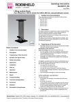
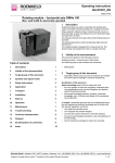
1
Operating instructions
BA_D8602
Issue 08-11
Pos : 1 /H eadli ne-Subline/060 H ydrauli k-Druc kerz eug er/062 Lufthydr aulisc he Spannpumpen/D 8602 H eadline-Subline @ 5\mod_1289214994003_12319.doc @ 57130 @ @ 1
Hydro-pneumatic pump unit
1
for single and double acting cylinders, max.
operating pressure 500 bar
Hydro-pneumatic pump units of data sheet D 8.602.
The following types or part numbers are concerned:
Validity of the documentation
Pos : 4.2 /Gültig keit der Dokumentation/060 H ydrauli k-Druc kerz eug er/062 Lufthydr aulisc he Spannpumpen/D 8602/D 8602 Gültig keit der D okumentati on @ 4\mod_1276083813838_12319.doc @ 49501 @ @ 1
Pos : 2 /Ti tel bilder/060 H ydrauli k-Druc kerzeuger/062 Lufthydraulisc he Spannpumpen/D 8602 Titelbil d @ 4\mod_1276083501729_0.doc @ 49494 @ @ 1
•
•
8601 211 - For single-acting cylinders
8601 221 - For double-acting cylinders
Pos : 5.1 /Ü bers chriften/Zi elgruppe @ 0\mod_1175588092656_12319.doc @ 12343 @ 1 @ 1
2
Target group of this document
Pos : 5.2 /Ü bers chriften/Bediener @ 3\mod_1251978681828_12319.doc @ 38042 @ 2 @ 1
2.1
Operator
Tasks:
Operation in setting or automatic mode.
Pos : 5.3 /Zi elgruppe/Allgemein/Bediener M ontage und H andhabungs tec hni k @ 3\mod_1251978618265_12319.doc @ 38036 @ @ 1
Qualification
No special requests, introduction on the basis of the operating
instructions, danger instruction, minimum age 18 years.
Pos : 5.4 /Ü bers chriften/F ac hpersonal @ 3\mod_1251978910686_12319.doc @ 38048 @ 2 @ 1
2.2
Qualified personnel
Tasks:
Transport, installation, start up, setting mode, trouble shooting,
putting out of service, checks, maintenance works.
Pos : 5.5 /Zi elgruppe/Allgemein/Aufg aben Montage und Handhabungstechni k @ 3\mod_1251978425290_12319.doc @ 38030 @ @ 1
Pos : 3.1 /Ü bers chriften/Inhalts verz eic hnis ohne N ummerierung @ 1\mod_1207045387656_12319.doc @ 14651 @ @ 1
Pos : 5.6 /Zi elgruppe/Allgemein/Zielgruppe, H ydraulik @ 0\mod_1175585991546_12319.doc @ 12323 @ @ 1
Table of contents
•
Pos : 3.2 /Inhal ts- und Stic hwortverz eichniss e/Automatisc hes Verz eichnis 1. Ebene @ 1\mod_1210245493625_12319.doc @ 18015 @ @ 1
1
Validity of the documentation
1
2
Target group of this document
1
3
Symbols and signal words
2
4
Safety instructions
2
5
Description
3
6
Application
4
7
Transport
5
8
Storage
5
9
Installation
6
10
Start up
8
11
Operation
9
12
Maintenance
11
13
Trouble shooting
14
14
Technical characteristics
15
15
Disposal
15
16
Declaration of manufacture
16
17
Index
17
Specialists, fitters and set-up men of machines and installations with hydraulic expert knowledge.
Qualification of the personnel
Expert knowledge means that the personnel must
• be in the position to read and completely understand technical specifications such as circuit diagrams and productspecific drawing documents,
• have expert knowledge (electric, hydraulic, pneumatic
knowledge, etc.) of function and design of the corresponding components.
Pos : 5.7 /Zi elgruppe/Allgemein/Qualifi kation des Personals @ 3\mod_1257326050003_12319.doc @ 40276 @ @ 1
An expert is somebody who has due to its professional education and experiences sufficient knowledge and is familiar with
the relevant regulations so that he
• can judge the entrusted works,
• can recognize the possible dangers,
• can take the required measures to eliminate dangers,
• knows the acknowledged standards, rules and guidelines of
the technology.
• has the required knowledge for repair and mounting.
Pos : 6.1 /Ü bers chriften/Symbole und Signal wörter @ 0\mod_1181550954328_12319.doc @ 12564 @ 1 @ 1
Pos : 4.1 /Ü bers chriften/Gültig keit der D okumentati on @ 0\mod_1175588091484_12319.doc @ 12335 @ 1 @ 1
Römheld GmbH • Postfach 1253 • 35317 Laubach • Germany • Tel.: +49 (0)6405 / 89-0 • Fax: +49 (0)6405 / 89-211 • www.roemheld.de
Subject to change without notice! Translation of the original German document
1 / 18
Operating instructions
BA_D8602
3
Symbols and signal words
4.2
General safety tips
Pos : 7.5 /Warnung/Verletz ung - Kundens eitig Schutz vorric htung vorsehen @ 4\mod_1277209359408_12319.doc @ 50070 @ @ 1
Pos : 6.2 /Symbol e und Signal wörter/Allgemein/Symbole und Signal wörter @ 1\mod_1208249887290_12319.doc @ 16743 @ @ 1
WARNUNG
DANGER
Danger of life / heavy health damages
Stands for an imminent danger.
If it is not avoided, death or very severe injuries will
result.
Injuries caused by missing safety devices!
To avoid injuries appropriate safety devices must be
provided by the customer.
Pos : 7.6 /Warnung/Verletz ung - durch Missachtung der Bedienungs anl eitung! @ 3\mod_1247639571272_12319.doc @ 37048 @ @ 1
WARNING
Person damage
Stands for a possibly dangerous situation.
If it is not avoided, death or very severe injuries will
result.
WARNING
Injuries due to non-compliance of the operating
instructions!
The product may only be operated, if the operating
instructions - especially the chapter "Safety instructions" have been read and understood.
Pos : 7.7 /Warnung/Verletz ung - besti mmungs wi drige Ver wendung, F ehlbedi enung oder Missbr auch! @ 2\mod_1219404580015_12319.doc @ 23964 @ @ 1
CAUTION
Easy injuries / property damage
Stands for a possibly dangerous situation.
If it is not avoided, minor injuries or material damages will result.
Hazardous to the environment
The symbol stands for important information for the
proper handling with materials that are hazardous to
the environment.
Ignoring these notes can lead to heavy damages to
the environment.
Mandatory sign!
The symbol stands for important information, necessary protection equipment, etc.
Note
This symbol stands for tips for users or especially useful
information. This is no signal word for a dangerous or
harmful situation.
Pos : 7.1 /Ü bers chriften/Sicherheits hinweis e @ 0\mod_1175588091937_12319.doc @ 12338 @ 1 @ 1
4
Safety instructions
Pos : 7.2 /Ü bers chriften/Grundl egende Infor mationen @ 2\mod_1220428110156_12319.doc @ 24975 @ 2 @ 1
4.1
Basic information
Pos : 7.3 /Sicherheits hi nweis e/Allgemei n/Grundl egende Hi nweis e für BA mit Konfor mität @ 3\mod_1249970773479_12319.doc @ 37500 @ @ 1
The operating instructions serve to information and avoidance
of dangers for transport, operation and maintenance.
Only in strict compliance with these operating instructions,
accidents and property damages can be avoided as well as
trouble-free operation of the product can be guaranteed.
Furthermore, the consideration of the operating instructions will
result in:
• reduced down times and repair costs,
• increased service life of the products.
Pos : 7.4 /Ü bers chriften/Allgemei ne Sic her hei tshi nweise @ 2\mod_1220854701453_12319.doc @ 25290 @ 2 @ 1
WARNING
Injuries due to misuse, incorrect operation or
abuse!
Injuries can occur if the product is not used within
the intended use and the technical performance
data.
Before start up, read the operating instructions!
Pos : 7.8 /Warnung/Verletz ung - ums türz endes Produkt - Tr ansport @ 1\mod_1207576318690_12319.doc @ 15711 @ @ 1
WARNING
Injury due to overturning product!
Overturning product due to inappropriate means of
transportation.
Do not stand below the load during lifting and lowering, stay outside the danger zone.
Use suitable means of transportation.
Pay attention to the weight of the equipment.
Pay attention that the product is safely located (centre of gravity see instruction sign).
Pos : 7.9 /Warnung/Vergiftung - durc h Kontakt mi t H ydrauli köl - Öl einfüllen @ 2\mod_1218793828107_12319.doc @ 23580 @ @ 1
WARNING
Poisoning due to contact with hydraulic oil!
For handling with hydraulic oil consider the material
safety data sheet.
Wear protection equipment.
Pos : 7.10 /War nung/Verletz ung - H oc hdr uc kinj ekti on - U nsachgemäß er Ansc hl uss mit H ydr auli kansc hluss @ 0\mod_1181641972765_12319.doc @ 12576 @ @ 1
WARNING
Injury by high-pressure injection (squirting out of
hydraulic oil under high pressure)!
Improper connection can lead to escapes of oil under
high pressure at the connections.
Mounting or dismounting of the element must only be
made in depressurised mode of the hydraulic system.
Connection of the hydraulic line as per
DIN 3852/ISO 1179.
Unused connections have to be locked professionally.
Use all mounting holes.
Pos : 7.11 /War nung/Verletz ung - Ver brennung durc h heiß es Öl! @ 1\mod_1208946178796_12319.doc @ 17046 @ @ 1
WARNING
Burning due to hot oil!
In operating conditions oil temperatures up to 70 °C
can appear due to environment influences.
All works must only be made in cool mode!
2 / 18
Operating instructions
BA_D8602
Pos : 7.12 /War nung/Verletz ung - Ver brennung durc h heiß e Oberfläc hen @ 0\mod_1181649006203_12319.doc @ 12578 @ @ 1
WARNING
Burning due to hot surface!
In operating conditions, surface temperatures of
more than 70 °C can appear at the product.
All maintenance and repair works must only be effected in cooled mode or with safety gloves.
Pos : 7.13 /War nung/Verletz ung - Ver brennung durc h el ektrisc hen Str om @ 1\mod_1207648041320_12319.doc @ 15980 @ @ 1
4.3
Pos : 8.3 /Gebotsz eic hen/Schutzhandsc huhe tragen @ 1\mod_1207557771937_12319.doc @ 15588 @ @ 1
For works at and with the product,
wear protective gloves!
Pos : 8.4 /Gebotsz eic hen/Schutzsc huhe trag en @ 1\mod_1207556472375_12319.doc @ 15579 @ @ 1
For works at and with the product,
wear safety shoes!
WARNING
Injury / burning due to contact with energized
parts!
Before working on electric equipment, the energized
parts must be de-energized and secured.
Do not open protection covers at electric parts.
All electrical works must only be realised by electricians.
Personal protective equipment
For works at and with the product,
wear safety goggles!
Pos : 8.2 /Gebotsz eic hen/Schutzbrille tragen @ 1\mod_1207557768203_12319.doc @ 15583 @ @ 1
Pos : 8.5 /Sicherheits hi nweis e/120 M ontage- und H andhabungstec hni k/Allgemein/Persönliche Sc hutz ausr üstung tragen @ 3\mod_1250670632857_12319.doc @ 37720 @ @ 1
For all works at the product, the operator has to make sure that
the necessary protection equipment will be worn.
Pos : 9 null------------ Spaltenumbruch ------------ @ 0\mod_1175587512406_12319.doc @ 12332 @ @ 1
Pos : 10.1 /Übersc hriften/Besc hrei bung @ 0\mod_1175588091203_12319.doc @ 12333 @ 1 @ 1
5
Description
Pos : 10.2 /Besc hrei bung/060 H ydr auli k-Druc kerz eug er/062 Lufthydr aulisc he Spannpumpen/D 8602/D 8602 Beschr eibung @ 4\mod_1276085975869_12319.doc @ 49520 @ @ 1
Pos : 7.14 /Vorsic ht/Beschädigung von Bauteilen! Arbeiten durc h F ac hpersonal durc hführ en lass en - Elektro - @ 2\mod_1218446795822_12319.doc @ 23371 @ @ 1
CAUTION
Damage of components!
Works only to be effected by authorised personnel.
Pos : 7.15 /Vorsic ht/Beschädigung von Bauteilen! Die z ul ässigen Leis tungsdaten des Pr oduktes, siehe Kapitel Techninis che @ 1\mod_1216302083387_12319.doc @ 19465 @ @ 1
Single-acting version
The hydro-pneumatic pump unit is manually operated. Only by
operating the pedal the fixture will be clamped or unclamped.
The pump delivers oil as long as the desired operating pressure
is obtained. Air pressure is adjusted by a pneumatic service
unit.
Oil pressure is maintained by an integrated check valve. The
pump does not automatically supply oil in case of leaks!
CAUTION
Damage of components!
The admissible performance data of the product,
see chapter "Technical characteristics", may not be
exceeded.
Pos : 7.16 /Vorsic ht/Beschädigung von H ydrauli kaggregat Drehfel drichtung ei nhalten @ 2\mod_1217332041708_12319.doc @ 21016 @ @ 1
CAUTION
Hydraulic power unit can be damaged!
Stick absolutely to the indicated direction of the
rotary field.
Pos : 7.17 /Vorsic ht/Beschädigung von Bauteilen! Durc h aggressi ve Rei nigungsmittel .. @ 3\mod_1251980826124_12319.doc @ 38054 @ @ 1
Double-acting version
By pushing the pedal, the connected double-acting hydraulic
cylinders are extended or retracted according to the position of
the 4/3 directional manual control valve. The pedal has to be
pushed as long as the cylinders are in its final position and the
desired oil pressure is obtained. After release of the pedal, the
pump does not re-deliver in case of pressure drop on the oil
side! The pedal can be locked by the laterally-arranged pin with
the description “PUSH INTO LOCK”, thereby the pump is continuously supplied with air. In this case the cylinders are exclusively activated by the 4/3 directional manual control valve.
Small leaks are compensated by the pump and the oil pressure
is maintained constantly.
CAUTION
Pos : 11 null------------ Spaltenumbruc h ------------ @ 0\mod_1175587512406_12319.doc @ 12332 @ @ 1
Damage of components!
The product must not be cleaned with:
• Corrosive or corroding components or
• Organic solvents as halogen or aromatic hydrocarbons and ketones (cellulose thinner, acetone,
etc.),
because this can destroy the seals.
Pos : 7.18 /Sic herheits hinweise/120 M ontage- und Handhabungstechni k/121 Drehmodul e horiz ontal /M1103 Dr ehmodul, el ektrisc hM 1103 Allgemeine Sic her heit @ 1\mod_1207633978179_12319.doc @ 15736 @ @ 1
Note - qualification of the user
All works may only be effected by qualified personnel
familiar with the handling of hydraulic components.
Pos : 8.1 /Ü bers chriften/Pers önlic he Schutz ausrüs tung @ 1\mod_1216726023632_12319.doc @ 19520 @ 2 @ 1
3 / 18
Operating instructions
BA_D8602
Pos : 12.1 /Übersc hriften/Ver wendung @ 0\mod_1175588092390_12319.doc @ 12341 @ 1 @ 1
6
Application
6.2
Misapplication
Pos : 12.6 /War nung/Verletz ung - Kei ne Modifi kati onen am Pr odukt vornehmen. @ 1\mod_1211264187111_12319.doc @ 18155 @ @ 1
Pos : 12.2 /Übersc hriften/Besti mmungsgemäß e Ver wendung @ 0\mod_1175588206140_12319.doc @ 12345 @ 2 @ 1
6.1
Intended use
Application
The hydro-pneumatic pump unit is particularly suitable for
smaller hydraulic clamping and assembly fixtures with single or
double-acting hydraulic elements.
Pos : 12.3 /Ver wendung/060 H ydrauli k-Druc kerz euger /062 Lufthydr aulisc he Spannpumpen/8602/D 8602 Eins atz @ 4\mod_1276086507771_12319.doc @ 49539 @ @ 1
Single-acting version
The hydro-pneumatic pump unit is manually operated. Only by
operating the pedal the fixture will be clamped or unclamped.
The pump delivers oil as long as the desired operating pressure
is obtained. Air pressure is adjusted by a pneumatic service
unit.
Oil pressure is maintained by an integrated check valve. The
pump does not automatically supply oil in case of leaks!
Double-acting version
By pushing the pedal, the connected double-acting hydraulic
cylinders are extended or retracted according to the position of
the 4/3 directional manual control valve. The pedal has to be
pushed as long as the cylinders are in its final position and the
desired oil pressure is obtained. After release of the pedal, the
pump does not re-deliver in case of pressure drop on the oil
side! The pedal can be locked by the laterally-arranged pin with
the description “PUSH INTO LOCK”, thereby the pump is continuously supplied with air. In this case the cylinders are exclusively activated by the 4/3 directional manual control valve.
Small leaks are compensated by the pump and the oil pressure
is maintained constantly.
Pos : 12.4 /Ver wendung/Allgemei n/Besti mmungsg emäß e Ver wendung, Druc kerz euger @ 4\mod_1267687824994_12319.doc @ 46670 @ @ 1
The products are used to generate hydraulic pressure in industrial applications for bending or clamping of workpieces and / or
to operate fixtures alternatively hydraulic actuators within
closed, low in dust rooms.
Furthermore the following belongs to possible uses:
• Use within the capacity indicated in the technical characteristics (see data sheet).
• Use as per operating instructions.
• Compliance with service intervals.
• Qualified and trained personnel for the corresponding activities.
• Mounting of spare parts only with the same specifications
as the original part.
WARNING
Injuries, material damages or malfunctions!
Do not modify the product!
Pos : 12.7 /Ver wendung/Allgemei n/Besti mmungs wi drige Ver wendung @ 3\mod_1258611534209_12319.doc @ 40640 @ @ 1
The use of these products is not admitted:
• For domestic use.
• On pallets or machine tool tables in primary shaping and
metal forming machine tools.
• If due to vibrations or other physical / chemical effects damages of the products or seals can be caused.
• In machines, on pallets or machine tool tables that are used
to change the characteristics of the material (magnetise, radiation, photochemical procedures, etc.).
• In areas for which special guidelines apply, especially installations and machines:
- For the use on fun fairs and in leisure parks.
- In food processing or in areas with special hygiene regulations.
- For military purposes.
- In mines.
- In explosive and aggressive environments (e.g. ATEX).
- In medical engineering.
- In the aerospace industry.
- For passenger transport.
• For other operating and environmental conditions e.g.:
- Higher operating pressures than indicated on the data
sheet or installation drawing.
- With hydraulic fluids that do not correspond to the specifications.
Pos : 13 null------------ Spaltenumbruc h ------------ @ 0\mod_1175587512406_12319.doc @ 12332 @ @ 1
Pos : 12.5 /Übersc hriften/Besti mmungs wi drige Ver wendung @ 0\mod_1175588251296_12319.doc @ 12346 @ 2 @ 1
4 / 18
Operating instructions
BA_D8602
Pos : 14.1 /Übersc hriften/Trans port @ 2\mod_1217322966174_12319.doc @ 20884 @ 1 @ 1
Pos : 16.1 /Übersc hriften/Lager ung @ 1\mod_1215424315328_12319.doc @ 19024 @ 1 @ 1
7
8
Transport
Pos : 14.2 /War nung/Verletz ung - umstürzendes Pr odukt - Trans port @ 1\mod_1207576318690_12319.doc @ 15711 @ @ 1
Storage
Pos : 16.2 /Vorsic ht/Lagerung, Aus wir kungen von U V-Lic ht, Ver harz ung, Korrosi onssc hutz @ 1\mod_1209716266257_12319.doc @ 17790 @ @ 1
WARNING
Injury due to overturning product!
Overturning product due to inappropriate means of
transportation.
Do not stand below the load during lifting and lowering, stay outside the danger zone.
Use suitable means of transportation.
Pay attention to the weight of the equipment.
Pay attention that the product is safely located (centre of gravity see instruction sign).
Pos : 14.3 /Gebotszei chen/Sc hutz ausrüs tung trag en @ 4\mod_1271410780776_12319.doc @ 48311 @ @ 1
For works at and with the product, wear suitable
protection equipment!
CAUTION
Damage of components!
The product may not be exposed to direct solar radiation, because the UV light can destroy the seals.
A storage differing from the storage conditions is
inadmissible.
In case of improper storage, the seals can embrittle
and resinification of the anti-corrosive oil or corrosion
at the element can occur.
Pos : 16.3 /Trans port/060 H ydrauli k-Druc kerzeuger/062 Lufthydraulisc he Spannpumpen/8602/Bes chr eibung Tr ansport Lufthydraulische Spannpumpe @ 4\mod_1276086731835_12319.doc @ 49558 @ @ 1
The product is delivered in a solid carton box.
To avoid damages to the product, maximally four individual
carton boxes may be put on top of each other.
Pos : 16.4 /Lager ung/060 H ydr auli k-Druc kerz euger/062 Lufthydraulische Spannpumpen/8602/D8602 Lagerung @ 4\mod_1276089922669_12319.doc @ 49620 @ @ 1
Pos : 14.4 /Trans port/060 H ydrauli k-Druc kerzeuger/062 Lufthydraulisc he Spannpumpen/8602/Bes chr eibung Tr ansport Lufthydraulische Spannpumpe @ 4\mod_1276086731835_12319.doc @ 49558 @ @ 1
The product is delivered in a solid carton box.
To avoid damages to the product, maximally four individual
carton boxes may be put on top of each other.
Pos : 14.5 /Hinweis/Produkt erst kurz vor der Montage aus dem Karton z u nehmen. @ 4\mod_1276088407472_12319.doc @ 49582 @ @ 1
Note
It is recommended to take the product out of the carton
box just before mounting.
Pos : 14.6 /Übersc hriften/Aus pac ken @ 4\mod_1276086936080_12319.doc @ 49576 @ 2 @ 1
7.1
Unpacking
When unpacking check the hydro-pneumatic pump unit for
possible damage.
Dents and fissures, etc. at the product may lead to oil leakages.
In this case do not install the pump!
Pos : 14.7 /Trans port/060 H ydrauli k-Druc kerzeuger/062 Lufthydraulisc he Spannpumpen/8602/Bes chr eibung Auspac ken @ 4\mod_1276086731554_12319.doc @ 49552 @ @ 1
ROEMHELD products are tested with mineral oil by default.
The exterior of the products is protected against corrosion.
The residual oil film after the test procedure provides for a sixmonth interior protection against corrosion when stored in dry
and tempered rooms.
For longer storage times the product must be filled with a nonresinifying corrosion protection agent and the external steel
surfaces must be treated.
The following storage conditions must be kept:
• Storage in original packing to keep away direct radiation or
harmful UV light
• Temperature between 10° and 50°C
• Relative humidity < 70 %,
Pos : 17 null------------ Spaltenumbruc h ------------ @ 0\mod_1175587512406_12319.doc @ 12332 @ @ 1
The empty packaging must be disposed in accordance with the
statuary regulations in the given country (see chapter disposal).
Pos : 15 null------------ Spaltenumbruc h ------------ @ 0\mod_1175587512406_12319.doc @ 12332 @ @ 1
5 / 18
Operating instructions
BA_D8602
Pos : 18.1 /Übersc hriften/Montage @ 0\mod_1175588091812_12319.doc @ 12337 @ 1 @ 1
9
Installation
Pos : 18.2 /Übersc hriften/Übersic ht der Komponenten @ 4\mod_1267712980591_12319.doc @ 46724 @ 2 @ 1
9.1
Overview of components
Pos : 18.3 /Montage/060 H ydrauli k-Druc kerzeuger/062 Lufthydraulische Spannpumpen/D 8602/D8602 Übersic ht der Komponenten 8602 211 @ 4\mod_1276171630339_12319.doc @ 49714 @ 3 @ 1
9.1.1
Overview 8602 211
Figure 3: Hydraulic connections
A Hydraulic port
B Hydraulic port
Pos : 18.5 null------------ Spaltenumbruc h ------------ @ 0\mod_1175587512406_12319.doc @ 12332 @ @ 1
Pos : 18.6 /Übersc hriften/Montagearten @ 0\mod_1179758624296_12319.doc @ 12411 @ 2 @ 1
9.2
Mounting types
Pos : 18.7 /Montage/060 H ydrauli k-Druc kerzeuger/062 Lufthydraulische Spannpumpen/D 8602/D8602 Montagearten @ 5\mod_1288093645871_12319.doc @ 56351 @ 2 @ 1
9.3
Mounting position
Figure 1: Schematic figure, components according to design
a
b
c
d
e
Bleeding screw
Pump pump pedal
"PUMP"
Pneumatic port G1/4, with
air filter
Oil level gauge
Reservoir
f
g
h
Filler and bleeding cap.
Hydraulic port, back G1/4
Release pressure release
pedal “RELEASE”
Pos : 18.4 /Montage/060 H ydrauli k-Druc kerzeuger/062 Lufthydraulische Spannpumpen/D 8602/D8602 Übersic ht der Komponenten 8602 221 @ 4\mod_1276498546077_12319.doc @ 49850 @ 3 @ 1
9.1.2
Overview 8602 221
Figure 4: Mounting position - horizontal
For perfect functioning and resucking of the hydraulic oil, the
hydro-pneumatic pump unit has to be installed horizontally.
Pos : 18.8 null------------ Spaltenumbruc h ------------ @ 0\mod_1175587512406_12319.doc @ 12332 @ @ 1
Figure 2: Schematic figure, components according to design
a
b
c
d
e
Bleeding screw
Pump pedal - Pump and
unlocking (k) of the locking button
Pneumatic port G1/4, with
air filter
Oil level gauge
Reservoir
F Filler and bleeding cap
g 2 x hydraulic port, back
G1/4
i 4/3 directional control
valve, manually operated
k Locking button of the
pump pedal
6 / 18
Operating instructions
BA_D8602
Pos : 18.9 /Übersc hriften/Instalation @ 4\mod_1269502635401_12319.doc @ 47727 @ 2 @ 1
9.4
Installation
Pos : 18.10 /Warnung/Verletzung - Podukt darf nic ht geöffnet werden, Kei ne Modifi kationen am Pr odukt vor nehmen. @ 3\mod_1258617417013_12319.doc @ 40730 @ @ 1
WARNING
Injuries, material damages or malfunctions!
The product must never be opened. At the product
no changes must be made, except the ones expressly mentioned in the operating instructions!
9.5
Connection of the hydraulic equipment
1. Connect hydraulic lines to qualifying standards and pay
attention to scrupulous cleanness (A = Extend, B = Retract)!
Pos : 18.13.2 /M ontage/Allgemei n/M ontage, H ydrauli k anschli eßen @ 0\mod_1175670055921_12319.doc @ 12354 @ @ 1
Pos : 18.13.3 /Hi nweis/Si ehe ROEMHELD Katal ogblätter A0100, F9300, F9310 und F 9360. @ 2\mod_1219750390607_12319.doc @ 24280 @ @ 1
Note
See ROEMHELD data sheets A 0.100, F 9.300, F 9.310
and F 9.360.
Pos : 18.11 /Vorsicht/Besc hädigung von Bauteilen! D urch uns ac hgemäß en Ans chl uss! @ 4\mod_1267686544330_12319.doc @ 46637 @ @ 1
CAUTION
Damage of components due to incorrect connection!
Incorrect connection can lead to faulty controls and
switchings and thus to damages.
Works only to be effected by qualified personnel.
Pos : 18.13.4 /Hi nweis/Versc hraubungen „Ei nsc hraubzapfen B“ nach DIN 3852 (ISO 1179) ver wenden. @ 1\mod_1207903725929_12319.doc @ 16575 @ @ 1
Note
Use only fittings "screwed plug B and E" as per DIN 3852
(ISO 1179).
Pos : 18.13.5 /Hi nweis/Ansc hl uss der H ydr auli k Kein Dichtband, keine Kupferringe und kei ne konisc hen Versc hraubung en ver wen @ 1\mod_1209472273487_12319.doc @ 17720 @ @ 1
Note
Do not use sealing tape, copper rings or coned fittings.
Pos : 18.12 /M ontage/060 H ydr auli k-Druc kerz euger/062 Lufthydr aulisc he Spannpumpen/D8602/D 8602 Abmess ungen - Bohrsc hablone @ 4\mod_1276171629996_12319.doc @ 49708 @ @ 1
CAUTION
Damage of the reservoir!
Oil can emerge.
The depth of the fixing holes of 20 mm/s must not be
exceeded.
Pos : 18.13.6 /Hi nweis/H ydrauli köl nach ROEMHELD Katal ogbl att A0100 @ 1\mod_1209472275830_12319.doc @ 17725 @ @ 1
Note
Use hydraulic oil as per ROEMHELD data sheet A 0.100.
Pos : 18.14.1 /Ü berschriften/Anschl uss der Pneumati k @ 4\mod_1276511727053_12319.doc @ 49905 @ 2 @ 1
9.6
Connection of pneumatic equipment
Pos : 18.14.2 /Gefahr/Gefahr durc h uner war teten Anl auf @ 5\mod_1284368549449_12319.doc @ 54181 @ @ 1
DANGER
The hydro-pneumatic pump unit can can be mounted in horizontal or vertical position.
The figure shows the distances and dimensions to the customer's fixing.
For fixing self-tapping screws for thermoplastics shoud be used
(example: Ø 5 - UNI 9707).
Unexpected start of the connected cylinders
when switching on the power units!
When switching on, the operating pressure will be
generated and in the process the cylinders can
move!
Secure the working area adequately!
Pos : 18.14.3 /Warnung/Warnung Hinweis z ur Abs chaltung @ 4\mod_1276514037010_12319.doc @ 49917 @ @ 1
WARNING
Unexpected start-up of the pump!
With locked pump pedal, unexpected start-up of the
pump may occur.
Install hand-operated valve in the pneumatic line for
quick switching off.
Pos : 18.14.4 /Hi nweis/Lufthydr aulisc hen Spannpumpe beginnt bei Ansc hluss an die pneumatisc he Vers orgung zu för der n. @ 5\mod_1288867333438_12319.doc @ 56922 @ @ 1
Important note
When connecting the product to the pneumatic supply
line, the hydro-pneumatic pump unit starts to deliver.
Pos : 18.14.5 /Hi nweis/Lufthydr aulisc hen Spannpumpe ei n Hand-Abs perr ventil zu ins tallier en @ 5\mod_1288696562839_12319.doc @ 56725 @ @ 1
Figure 5: Dimensions for fixing
Pos : 18.13.1 /Ü berschriften/Anschl uss der H ydrauli k @ 0\mod_1175671167296_12319.doc @ 12359 @ 2 @ 1
Important note
We recommend to install a hand-operated shut-off valve
just in front of the hydro-pneumatic pump unit. By this
valve the hydro-pneumatic pump unit can be quickly
switched off in case of emergency or for maintenance
works.
Pos : 18.14.6 /M ontage/Allgemei n/M ontage, Pneumatli k ansc hließ en @ 4\mod_1276511579574_12319.doc @ 49899 @ @ 1
1. Connect pneumatic lines to qualifying standards and pay
attention to scrupulous cleanness!
Accessories see also data sheet J 7.400.
Pos : 18.15 null------------ Spaltenumbr uch ------------ @ 0\mod_1175587512406_12319.doc @ 12332 @ @ 1
7 / 18
Operating instructions
BA_D8602
Pos : 19.1 /Übersc hriften/Inbetriebnahme @ 0\mod_1175588091625_12319.doc @ 12336 @ 1 @ 1
10 Start up
Pos : 19.2 /Übersc hriften/Öl einfüll en @ 0\mod_1179825257125_12319.doc @ 12441 @ 2 @ 1
10.1
Charging with hydraulic oil
Pos : 19.3 /War nung/Vergiftung - durch Kontakt mit H ydr auli köl - Öl ei nfüllen @ 2\mod_1218793828107_12319.doc @ 23580 @ @ 1
WARNING
Poisoning due to contact with hydraulic oil!
For handling with hydraulic oil consider the material
safety data sheet.
Wear protection equipment.
Procedure:
• Pull out the filler cap by means of a flat screw driver and
remove the cap.
• For oil filling use funnel with filter cloth (see purity class)!
Pay attention to the indicated oil volume (see technical
characteristics).
• Clean filler opening and cap.
• Insert and push in the cap.
Pos : 19.15 /Inbetriebnahme/060 H ydrauli k-Druc kerzeuger/062 Lufthydraulisc he Spannpumpen/8602/D 8602 Inbetri ebnahme @ 4\mod_1276511272117_12319.doc @ 49881 @ 332 @ 1
Pos : 19.4 /Gebotszei chen/Sic herheits D atenbl ätter beac hten! @ 4\mod_1271411891976_12319.doc @ 48335 @ @ 1
For works with operating fluids, pay attention to
the safety data sheets!
10.1.1
Preparation of mounting
Pos : 19.5 /Gebotszei chen/Sc hutz ausrüs tung trag en @ 4\mod_1271410780776_12319.doc @ 48311 @ @ 1
For works at and with the product, wear suitable
protection equipment!
Pos : 19.6 /Hinweis/Dr uc kerzeuger wir d ohne Ölfüllung geliefer t @ 2\mod_1217332494024_12319.doc @ 21119 @ @ 1
Important!
The pressure generator is delivered without oil filling.
Filling must only be made when the connected hydraulic
drives and accumulators are in off-position.
Accumulated oil volume in drives or accumulators can
lead to overflowing of the oil reservoir!
Pos : 19.7 /Hinweis/D as Betrei ben der Pr odukte mi t Druc kflüssigkeiten, die nic ht den Vorgaben entspr ec hen, ist unzul ässi @ 1\mod_1209018135875_12319.doc @ 17060 @ @ 1
Note
Operation of the products with hydraulic fluids that do not
correspond to the specifications is inadmissible. See
technical characteristics:
Pos : 19.8 /Hinweis/H ydr auli köl nac h R OEMH ELD Katalog blatt A0100 @ 1\mod_1209472275830_12319.doc @ 17725 @ @ 1
Note
Use hydraulic oil as per ROEMHELD data sheet A 0.100.
Pos : 19.9 /Hinweis/Keine Fremdteile (Späne etc.) mit in das H ydrauli kaggregat eing efüllt @ 2\mod_1217332833781_12319.doc @ 21124 @ @ 1
Note!
No impurities must enter into the oil reservoir.
Use clean filter cloth!
Figure 6: Unscrewed bleeding screw
Unscrew the bleeding screw (a) by three to four revolutions.
10.1.2
Connection of the tank pipe (in double-acting applications)
Procedure:
• Put the hydro-pneumatic pump unit onto a plane and horizontal base. If necessary, this can be made at the installation point.
• If the bleeding cap was pulled out, completely push in the
cap.
• Unscrew the locking pin of the cap and screw in a NPTF
fitting (3/8 NPTF).
Pos : 19.10 /Inbetriebnahme/060 H ydrauli k-Druc kerzeuger/Allgemei n/Hi nweis schil der beac hten @ 5\mod_1282038927579_12319.doc @ 53036 @ @ 1
Follow the signs
10.2
Connection of compressed-air pipe
Pos : 19.11 /Hi nweis/Hinweissc hild: Vor Ölei nfüllen Entlüftungssc hraube M 6 her ausdr ehen. @ 5\mod_1282038715932_12319.doc @ 53030 @ @ 1
(For power units with piston pumps or double pumps with gear
and piston pump combinations)
Attention!
Before filling the oil unscrew bleeding screw M6. Screw in
again after filling.
Pos : 19.12 /Hi nweis/Hinweissc hild: Hi er Öl einfüll en @ 5\mod_1282039186911_12319.doc @ 53042 @ @ 1
Note
Fill with oil here.
Procedure:
• Screw in fitting at compressed air connection.
• Connect to the compressed-air system.
Pos : 19.16 /Hi nweis/Lufthydr aulisc hen Spannpumpe ei n H and-Abs perr ventil zu ins tallier en @ 5\mod_1288696562839_12319.doc @ 56725 @ @ 1
Important note
We recommend to install a hand-operated shut-off valve
just in front of the hydro-pneumatic pump unit. By this
valve the hydro-pneumatic pump unit can be quickly
switched off in case of emergency or for maintenance
works.
Pos : 19.13 /Hi nweis/Hinweissc hild: H ydrauli köl nac h DIN 51524-2 HLP 22 ver wenden @ 5\mod_1282040322579_12319.doc @ 53048 @ @ 1
For piston pumps
Use hydraulic oil as per DIN 51524-2 HLP 22.
Pos : 19.17 /Ü berschriften/Entlüften der H ydrauli k @ 0\mod_1179825571390_12319.doc @ 12443 @ 2 @ 1
Pos : 19.14 /Inbetriebnahme/060 H ydrauli k-Druc kerzeuger/062 Lufthydraulisc he Spannpumpen/8602/D 8602 Bei m Öleinfüll en ist wi e folgt vorz ugehen @ 5\mod_1288089459302_12319.doc @ 56345 @ @ 1
In the chapter "Technical characteristics" the oil volumes and
the effectively usable oil volume are indicated, that can be filled
in and used depending on the mounting position.
8 / 18
Operating instructions
BA_D8602
10.3
Bleeding of the hydraulic system
Hazardous to the environment
In case of improper use leaking oil can lead to environmental pollution
Pay attention to the notes for appropriate handling.
Pos : 19.18 /Gefahr/U mweltgefährlich, ausl aufendes Öl bei uns ac hgemäßen U mgang @ 4\mod_1276513768956_12319.doc @ 49911 @ @ 1
11 Operation
Pos : 20.2 /War nung/Verletz ung - H oc hdr uc kinj ekti on - U nsachgemäß er Ansc hl uss ohne H ydrauli kansc hluss @ 2\mod_1222326644527_12319.doc @ 25670 @ @ 1
WARNING
Injury by high-pressure injection (squirting out
of hydraulic oil under high pressure)!
Improper connection and use can lead to escapes of
oil under high pressure at the seals.
Mounting or dismounting of the element must only
be made in depressurised mode.
Fixing has to be made in an appropriate way.
Pos : 19.19 /Warnung/Vergiftung - durc h Kontakt mit H ydrauli köl! @ 1\mod_1207634032554_12319.doc @ 15740 @ @ 1
WARNING
Poisoning due to contact with hydraulic oil!
Wear, damage of the seals, ageing and incorrect
mounting of the seal kit by the operator can lead to
escapes of oil.
Incorrect connection can lead to escapes of oil at
the ports.
For handling with hydraulic oil consider the material
safety data sheet.
Wear protection equipment.
Pos : 20.3 /War nung/Verletz ung - H oc hdr uc kinj ekti on - Versc hleiß , Besc hädig ung der Dic htungen, Alterung @ 1\mod_1215171972248_12319.doc @ 18990 @ @ 1
WARNING
Injury by high-pressure injection (squirting out of
hydraulic oil under high pressure)!
Wear, damage of the seals, ageing and incorrect
mounting of the seal kit by the operator can lead to
escapes of oil under high pressure.
Before using them make a visual control.
Pos : 19.20 /Inbetriebnahme/060 H ydrauli k-Druc kerzeuger/Allgemei n/Beschr eibung Entlüftung Dr uc kerzeuger T eil 1 N achteil e @ 4\mod_1267778792285_12319.doc @ 46755 @ @ 1
After filling the hydraulic oil there is still residual air in the internal and external pipes and the hydraulic drives (hydraulic cylinders, etc).
Air in hydraulic systems has among other things the following
undesirable effects:
• longer extending and retracting times e.g. of the hydrocylinder.
• short cycling
• Accelerated ageing of the oil.
• Increased wear at seals and pump.
Pos : 20.4 /Vorsic ht/Beschädigung von Bauteilen! Druc k auf Ölbehälter @ 4\mod_1271671473350_12319.doc @ 48440 @ @ 1
CAUTION
Damage of components or malfunction due to
pressure on oil reservoir!
Oil reservoir can be damaged!
Open oil filler / bleeding screw one revolution, so
that a pressure compensation takes place.
Pos : 20.5 /Betri eb/060 H ydraulik-Dr uc kerzeuger/062 Lufthydraulische Spannpumpen/8602/D8602 Betrieb @ 5\mod_1288100177250_12319.doc @ 56361 @ 22333 @ 1
11.1
Single-acting version
To avoid these undesirable effects the whole hydraulic system
(power unit, valves, drives and piping) have to be bled by repeated operation of the hydraulic drive!
Pos : 19.21 /Inbetriebnahme/060 H ydrauli k-Druc kerzeuger/Allgemei n/Beschr eibung Entlüftung Dr uc kerzeuger T eil 2 Vorgehens weis e @ 0\mod_1179825618500_12319.doc @ 12444 @ @ 1
Procedure:
1. For bleeding the oil pressure has to be reduced to a very
low value!
2. Adjust pressure relief valve to the lowest possible value by
screwing counterclockwise (see section "Adjust operating
pressure" in the chapter "Operation").
3. Pressurise clamping line.
4. Loosen carefully a bleeding screw or a fitting at the highest
or remotest point of the fixture.
5. Pump until bubble free oil comes out.
6. Close bleeding point.
7. If double-acting elements are used, bleeding has to be
effected also for the unclamping line.
8. Refill lost oil.
Note
Carry out function test.
The operating direction of the control units must be
obvious to the direction of motion of the plant.
Pos : 20.1 /Übersc hriften/Betrieb @ 2\mod_1225267007734_12319.doc @ 28945 @ 1 @ 1
Figure 7: Operation of the single-acting version
Procedure:
• Press the marked point with the inscription “PUMP” with
the foot.
• When releasing the pedal no further pressure will be built
up. The obtained pressure is maintained.
• To reduce the pressure the pedal is operated at the marked
point with the inscription “RELEASE”.
9 / 18
Operating instructions
BA_D8602
11.2
Double-acting version
Figure 8: Operation of the double-acting version
Procedure:
The double-acting hydro-pneumatic pump unit can be used
with intermittent or continuous operation.
Intermittent operation:
• Press the marked point with the inscription “PRESS TO
RELEASE LOCK” with the foot.
• When releasing the pedal no further pressure will be built
up. The obtained pressure is maintained.
11.2.1 Switch on continuous operation:
• Press the marked point with the inscription “PRESS TO
RELEASE LOCK” with the foot.
Press the locking pin "PUSH PIN TO LOCK", to maintain
the pedal in the pump position.
• Now the connected consumer element can be operated
with the 4/3 directional control valve.
11.2.3
Operation with 4/3 directional manual control
valve:
Figure 9: Valve positions of the double-acting version
The hydro-pneumatic pump unit is equipped with one 4/3 directional manual control valve. This enables the operation of double-acting consumer elements.
• Position A: Pressure on port "A", return of the hydraulic oil
via port "B" to the reservoir.
• Position B: Pressure on port "B", return of the hydraulic oil
via port "B" to the reservoir.
• Position N: In the centre position the ports are locked, the
pump stops.
This function can be controlled in continuous or intermittent
operation.
Note
If the double-acting hydro-pneumatic pump unit is used to
operate a single-acting consumer element, the unused
port has to be locked by a screw plug.
Pos : 21.1 /Übersc hriften/Wartung @ 0\mod_1175588092531_12319.doc @ 12342 @ 1 @ 1
11.2.2 Switch off continuous operation:
• Press the marked point with the inscription “PRESS TO
RELEASE LOCK” with the foot.
Thereby locking is released, the locking pin releases the
pedal.
10 / 18
Operating instructions
BA_D8602
12 Maintenance
12.4 Yearly checks
Hydraulic system, hydraulic hoses
An expert has to check all hydraulic components at least once
a year if they are still work-proof. Assessed damages have to
be repaired immediately.
Pos : 21.13 /Wartung/060 H ydr auli k-Druc kerz euger/Allgemei n/J ährlic he Prüfungen H ydrauli kanl age, H ydr auli ks chl äuche @ 4\mod_1270123716730_12319.doc @ 47853 @ @ 1
#
Pos : 21.2 /Vorsic ht/Leichte Verletz ungen Pr odukt vor Wartungsarbeiten von Energiez ufuhr trennen. @ 5\mod_1288182296597_12319.doc @ 56456 @ @ 1
CAUTION
Unexpected start or movement!
In case of unexpected start or stored energy injuries
can occur.
Prior to the maintenance works, the product is to be
separated from the energy supply and the pressure
lines have to be depressurised.
Pos : 21.3 /Gebotszei chen/Sc hutz ausrüs tung trag en @ 4\mod_1271410780776_12319.doc @ 48311 @ @ 1
For works at and with the product, wear suitable
protection equipment!
The following checks and works have to be effected:
• An expert has to check all hydraulic hoses at least once a
year if they are still work-proof. Assessed damages have to
be repaired immediately.
• The hydraulic hoses of the device have to be exchanged as
per BGR 237 at least after 6 years by new ones.
Pos : 21.14 null------------ Spaltenumbr uch ------------ @ 0\mod_1175587512406_12319.doc @ 12332 @ @ 1
Pos : 21.15 /Ü berschriften/R einig ung @ 0\mod_1175588402921_12319.doc @ 12347 @ 2 @ 1
Pos : 21.4 /Hinweis/Betriebs anl eitungen für einzel ne Komponenten i m Internet oder auf Anfrag e @ 4\mod_1268313753595_12319.doc @ 47348 @ @ 1
Note
Further operating instructions for individual components
are available in the internet (www.ROEMHELD.com) or
on request!
Pos : 21.5 /Übersc hriften/Wartungsplan @ 0\mod_1179931358453_12319.doc @ 12496 @ 2 @ 1
12.1 Plan for maintenance
Maintenance
Interval
works
Cleaning
As required
Check
daily
Checking of hydrau- yearly
lic system and
components
Exchange of the
after 250 operathydraulic fluid after
ing hours or 3
start up
months
Check the hydraulic after 1250 operfluid
ating hours or 6
months
Exchange of
in case of dahydraulic fluids
mages
Repair
Pos : 21.6 /Wartung/060 H ydrauli k-Druc kerzeuger/Allgemei n/Wartungspl an Druc kerz euger allgemei n @ 5\mod_1284381520532_12319.doc @ 54278 @ @ 1
Realisation
Operator
Operator
Qualified personnel
Qualified personnel
Qualified personnel
Qualified personnel
ROEMHELD service staff
Pos : 21.7 null------------ Spaltenumbruc h ------------ @ 0\mod_1175587512406_12319.doc @ 12332 @ @ 1
Pos : 21.8 /Übersc hriften/Reg elmäßige Kontrollen @ 0\mod_1175588442187_12319.doc @ 12348 @ 2 @ 1
12.2 Regular checks
Checks by the operator have to be effected as follows:
Pos : 21.9 /Wartung/120 Montage- und Handhabungstechni k/Allgemei n/R egel mäßig e Kontroll en @ 2\mod_1218442062281_12319.doc @ 23326 @ @ 1
#
Pos : 21.10 /Ü berschriften/T ägliche Prüfungen @ 0\mod_1179931403062_12319.doc @ 12497 @ 2 @ 1
12.3 Daily checks
• Check all fixing screws, retighten if required.
• Check all cable fixings and fittings, retighten if required.
• Check hydraulic components for external leakage - retighten fittings, if required.
• Hydraulic hoses must not get in contact with substances
which can cause a damage (acids, lys, solvents, ....).
• Check the oil level of the hydraulic power unit (see chapter
Charging of the hydraulic power unit with oil) - if required refill oil (specifications see chapter Technical characteristics).
• Check safety devices as per chapter Safety devices.
Pos : 21.11 /Wartung/Allgemei n/T ägliche Prüfungen Druc kerz eug er und Ei npress vorrichtungen @ 2\mod_1218442471515_12319.doc @ 23351 @ @ 1
#
Pos : 21.12 /Ü berschriften/J ährliche Prüfungen @ 0\mod_1179931443171_12319.doc @ 12498 @ 2 @ 1
11 / 18
Operating instructions
BA_D8602
Pos : 21.20.1 /Ü berschriften/Wartung und Prüfung der Dr uc kfl üssig keit @ 5\mod_1284444939614_12319.doc @ 54360 @ 2 @ 1
12.5
Cleaning
Pos : 21.16 /Warnung/Verletzung - durc h her aus fliegende Teil e oder Öl! @ 3\mod_1252045546672_12319.doc @ 38070 @ @ 1
12.6 Maintenance and check of the hydraulic fluid
Important factors that influence the degree of contamination of
the hydraulics fluid are:
• Contamination of the surroundings
• Size of the hydraulic system
• Design of the hydraulic system as specified
• Number of consumer elements,
• Cycle time,
• Number of fluid circulations through the filter per time unit,
• Implementation of the maintenance schedules,
• Training of the maintenance personnel.
They change the operating characteristics of hydraulic fluids
and lead to their ageing.
The monitoring of the condition and a filtration adapted to the
requirements of the application (if necessary, draining and
degasification) are indispensable for the maintenance of the
operating characteristics and guarantee of a long service life of
hydraulic fluids and components.
The hydraulic fluid must be regularly exchanged or examined
by the lubricant manufacturer and/or qualified staff.
A reference investigation according to the maintenance schedule with analysis as per ISO 4406 or mass of impurities with
analysis as per E 12662 is recommended
Pos : 21.20.2 /Wartung/060 H ydr auli k-Druc kerz euger/Allgemein/Wartung und Pr üfung der Druc kflüs sigkeit @ 5\mod_1284445358409_12319.doc @ 54381 @ @ 1
WARNING
Injury by flying out components or oil!
For cleaning works always wear safety goggles,
protective shoes and safety gloves.
Pos : 21.17 /Vorsicht/Besc hädigung von Bauteilen! D urch aggressi ve R einig ungs mittel.. @ 3\mod_1251980826124_12319.doc @ 38054 @ @ 1
CAUTION
Damage of components!
The product must not be cleaned with:
• Corrosive or corroding components or
• Organic solvents as halogen or aromatic hydrocarbons and ketones (cellulose thinner, acetone,
etc.),
because this can destroy the seals.
Pos : 21.18 /Wartung/060 H ydr auli k-Druc kerz euger/062 Lufthydr aulische Spannpumpen/8602/D8602 R einig ung @ 5\mod_1288179485060_12319.doc @ 56444 @ @ 1
The following cleaning works have to be effected daily at the
hydro-pneumatic pump unit:
•
•
Clean the product only with cleaning clothes.
Afterwards lubricate slightly movable components (pedal,
locking pin, etc.) and not coated steel components.
Note
For guarantee, liability and warranty claims, maintenance
proofs and/or the results of analysis of the hydraulic fluids
have to be submitted to us.
Pos : 21.21 null------------ Spaltenumbr uch ------------ @ 0\mod_1175587512406_12319.doc @ 12332 @ @ 1
Figure 10: Air filter
•
In the interior of the pneumatic port there is an air filter.
- Unscrew the filter in the compressed-air connection by
means of a screwdriver.
- Clean the filter with compressed air (from the inside
outwards).
- Insert and fasten the filter.
Attention: Don't screw too tight to avoid damage of the
thread.
- Screw in compressed air connection.
Note
If the filter is excessively polluted or damaged, the filter
must be exchanged. A new filter can be ordered from the
manufacturer.
Pos : 21.19 null------------ Spaltenumbr uch ------------ @ 0\mod_1175587512406_12319.doc @ 12332 @ @ 1
12 / 18
Operating instructions
BA_D8602
Pos : 21.22.1 /Ü berschriften/Öl wec hs el durc hführ en @ 0\mod_1179905129484_12319.doc @ 12461 @ 2 @ 1
12.7
Oil change
Hazardous to the environment
Due to possible environmental pollution, the individual components should be disposed only by an
authorised expert company.
Pos : 21.22.2 /Gefahr/U mweltgefährlich, durc h F achunternehmen entsorgen l ass en @ 1\mod_1209717325929_12319.doc @ 17795 @ @ 1
Pos : 21.22.13 /Hi nweis /H ydr auli köl nac h R OEMH ELD Katal ogblatt A0100 @ 1\mod_1209472275830_12319.doc @ 17725 @ @ 1
Note
Use hydraulic oil as per ROEMHELD data sheet A 0.100.
Pos : 21.22.14 /Hi nweis /Keine Fr emdteil e (Späne etc.) mi t in das H ydr auli kaggregat ei ngefüllt @ 2\mod_1217332833781_12319.doc @ 21124 @ @ 1
Note!
No impurities must enter into the oil reservoir.
Use clean filter cloth!
Pos : 21.22.3 /Warnung/Verletz ung - Verbr ennung durch heißes Öl! @ 1\mod_1208946178796_12319.doc @ 17046 @ @ 1
WARNING
Burning due to hot oil!
In operating conditions oil temperatures up to 70 °C
can appear due to environment influences.
All works must only be made in cool mode!
Pos : 21.22.15 /Inbetriebnahme/060 H ydr auli k-Druc kerz euger/Allgemein/Hinweissc hilder beac hten @ 5\mod_1282038927579_12319.doc @ 53036 @ @ 1
Follow the signs
Pos : 21.22.16 /Hi nweis /Hinweissc hild: Hier Öl ei nfüllen @ 5\mod_1282039186911_12319.doc @ 53042 @ @ 1
Note
Fill with oil here.
Pos : 21.22.17 /Hi nweis /Hinweissc hild: H ydr auli köl nach DIN 51524- 2 H LP 22 ver wenden @ 5\mod_1282040322579_12319.doc @ 53048 @ @ 1
Pos : 21.22.4 /Warnung/Verletz ung - Verbr ennung durch heiße Oberfl äc hen @ 0\mod_1181649006203_12319.doc @ 12578 @ @ 1
WARNING
Burning due to hot surface!
In operating conditions, surface temperatures of
more than 70 °C can appear at the product.
All maintenance and repair works must only be effected in cooled mode or with safety gloves.
Pos : 21.22.5 /Warnung/Vergiftung - durc h Kontakt mit H ydrauli köl - Öl einfüll en @ 2\mod_1218793828107_12319.doc @ 23580 @ @ 1
WARNING
Poisoning due to contact with hydraulic oil!
For handling with hydraulic oil consider the material
safety data sheet.
Wear protection equipment.
For piston pumps
Use hydraulic oil as per DIN 51524-2 HLP 22.
Pos : 21.22.18 /Inbetriebnahme/060 H ydr auli k-Druc kerz euger/062 Lufthydr aulis che Spannpumpen/8602/D 8602 Beim Öl einfüllen is t wie folgt vorzugehen @ 5\mod_1288089459302_12319.doc @ 56345 @ @ 1
In the chapter "Technical characteristics" the oil volumes and
the effectively usable oil volume are indicated, that can be filled
in and used depending on the mounting position.
Procedure:
• Pull out the filler cap by means of a flat screw driver and
remove the cap.
• For oil filling use funnel with filter cloth (see purity class)!
Pay attention to the indicated oil volume (see technical
characteristics).
• Clean filler opening and cap.
• Insert and push in the cap.
Pos : 21.22.6 /Vorsicht/Besc hädigung von Bauteil en! Kurzs chl uss von i nter nen Bauteil en durch Was ser eintr ag- Öl wechs el einhal @ 4\mod_1270127376197_12319.doc @ 47897 @ @ 1
CAUTION
Pos : 22 null------------ Spaltenumbruc h ------------ @ 0\mod_1175587512406_12319.doc @ 12332 @ @ 1
Short circuit of internal components!
In case of high water entry (condensation, coolants,
etc.) into the oil reservoir, a short circuit can result.
It is imperative to stick to the interval for the oil
change!
Pos : 21.22.7 /Gebotsz eic hen/Sic her heits Datenblätter beachten! @ 4\mod_1271411891976_12319.doc @ 48335 @ @ 1
For works with operating fluids, pay attention to
the safety data sheets!
Pos : 21.22.8 /Gebotsz eic hen/Sc hutzausr üstung tragen @ 4\mod_1271410780776_12319.doc @ 48311 @ @ 1
For works at and with the product, wear suitable
protection equipment!
Pos : 21.22.9 /Hi nweis/Öl wec hsel nur i m kalten Zustand durc hführ en. @ 1\mod_1209018143234_12319.doc @ 17070 @ @ 1
Note
Oil changes must only be made in depressurised mode.
Pos : 21.22.10 /Hi nweis /H ydr auli köl gemäß Hi nweis schil d am Öl einfülls tutzen ver wenden. @ 5\mod_1284381248570_12319.doc @ 54242 @ @ 1
Note
Use hydraulic oil as per sign at the oil filler neck (see also
technical characteristics).
Pos : 21.22.11 /Hi nweis /Angaben z ur Filterung und R einhei ts klasse der Druc kfl üssig keit beachten @ 5\mod_1284961524904_12319.doc @ 54440 @ @ 1
Note
Pay attention to the indication for filtration and purity class
of the hydraulic fluid (see technical characteristics).
Pos : 21.22.12 /Hi nweis /Das Betr eiben der Produkte mit Druc kfl üssig keiten, die nic ht den Vorgaben ents prec hen, ist unz ulässi @ 1\mod_1209018135875_12319.doc @ 17060 @ @ 1
Note
Operation of the products with hydraulic fluids that do not
correspond to the specifications is inadmissible. See
technical characteristics:
13 / 18
Operating instructions
BA_D8602
Pos : 23.1 /Übersc hriften/Stör ungs bes eitigung @ 0\mod_1175588092078_12319.doc @ 12339 @ 1 @ 1
13 Trouble shooting
Pos : 23.2 /Stör ungs beseitig ung/060 H ydr auli k-Druc kerz eug er/062 Lufthydr aulisc he Spannpumpen/8602/D 8602 Störungsbes eitigung @ 5\mod_1288187611589_12319.doc @ 56463 @ @ 1
In the following section, some anomalies are listed, that can
occur during the operation, beside it some remedies are described.
If the problems cannot be solved with the described procedure,
please contact the manufacturer.
Trouble
Pump does not
start
The pump stops
under load
The pump runs,
but no pressure is
built up.
Cause
The supply line of
the compressed
air is closed or is
clogged.
Air pressure is
too low
Air filter is contaminated or
clogged.
Leakage at consumer elements
Leakage in the
pump
Oil level is too low
The pump does
not obtain the
adjusted operating
pressure.
Air pressure is
too low
Interior safety
valve misaligned.
Leakage at consumer elements
The pump generates pressure, but
the connected
consumer elements do not
move.
Overload
The oil does not
circulate correctly.
Remedy
Make sure that
the compressed
air is supplied to
the pump.
Make sure that
the pneumatic
pressure of the
pump is between
2.8 and 10 bar.
Clean or replace
air filter.
Check whether
there is a leakage
and repair, if
necessary.
Caution !
Works only by
ROEMHELD
experts
Check oil level
and refill, if necessary.
Make sure that
the pneumatic
pressure of the
pump is between
2.8 and 10 bar.
Switch off the
pump, inform
manufacturer.
Consumer element retracts,
despite the fact
that release is not
pressed.
Single-acting
consumer element
does not retract to
off-position
Double-acting
consumer element
does not move.
Insufficient pump
performance.
Leakage at consumer elements
Defect in the
pump
Hydraulic line
squeezed
For consumer
elements without
spring return: not
sufficient retracting weight.
Hydraulic line
squeezed
Manual valve in
incorrect position.
Air pressure is
too low
Air filter is contaminated or
clogged.
Reservoir was not
bled
Check whether
there is a leakage
and repair, if
necessary.
Switch off the
pump, inform
manufacturer.
Caution !
Works only by
ROEMHELD
experts
Check hydraulic
line
Check and remedy.
Check hydraulic
line
Check and remedy.
Make sure that
the pneumatic
pressure of the
pump is between
2.8 and 10 bar.
Clean or replace
air filter.
Check and remedy.
Pos : 23.3 null------------ Spaltenumbruc h ------------ @ 0\mod_1175587512406_12319.doc @ 12332 @ @ 1
Caution !
Work only by
ROEMHELD
experts
Check whether
there is a leakage
and repair, if
necessary.
Check performance data of the
consumer element and the
pump.
Control whether
the lines are
kinked and/or
squeezed,
whether there are
jam points or
whether the cylinder is defect.
14 / 18
Operating instructions
BA_D8602
Pos : 24 null------------ Spaltenumbruc h ------------ @ 0\mod_1175587512406_12319.doc @ 12332 @ @ 1
Pos : 25.1 /Übersc hriften/Technisc he Daten @ 0\mod_1175588092203_12319.doc @ 12340 @ 1 @ 1
14 Technical characteristics
Pos : 25.2 /T echnisc he Daten/060 H ydr auli k-Druc kerz euger/061 Pumpenaggregate/Druc kfl üssig keiten/Druc kfl üssigkeiten @ 5\mod_1284374034570_12319.doc @ 54230 @ @ 1
Hydraulic fluids
Details of the hydraulic fluids to be used are attached to the oil
filler neck.
Pos : 25.3 /Hinweis/Hi nweis schil d: H ydr auli köl nac h D IN 51524- 2 H LP 22 ver wenden @ 5\mod_1282040322579_12319.doc @ 53048 @ @ 1
For piston pumps
Use hydraulic oil as per DIN 51524-2 HLP 22.
Pos : 25.4 /T echnisc he Daten/060 H ydr auli k-Druc kerz euger/061 Pumpenaggregate/Druc kfl üssig keiten/R einhei t der Dr uc kfl üssig kei ten @ 5\mod_1284374380878_12319.doc @ 54236 @ @ 1
Purity of the hydraulic fluids
The admissible contamination (unsolved impurities in the hydraulic fluid) depends on the component of the hydraulic system that is most sensitive to dirt. The indicated purity class is
the maximally admissible value that should not be exceeded,
with regard to the operating safety (clogging of gaps, orifices as
well as the locking of the control piston) and the service life
(wear reduction).
Application
Minimum
Minimum
attainable
purity as
purity as
with filter
per
per
fineness *
NAS 1638
ISO 4406
Radial piston
8
and gear
(recom20 / 17 / 13
≤ 20 µm
pumps, valves
mended:
and cylinders
5 up to 7)
Proportional
7
pressure and
(recom18 / 16 / 13
≤ 10 µm
flow control
mended:
valves
5 up to 6)
* Important influential factors see chapter: "Maintenance and
check of the hydraulic fluid"
In particular with proportional valves, the repetitive accuracy
depends especially on the purity degree of the hydraulic fluid.
Note
Please note that a new hydraulic fluid "on tap" does not
necessarily meet the highest requirements of cleanness.
Note
Mixing of different types of hydraulic fluid can lead to
unintended chemical reactions with mud formation resinification or similar.
Therefore, the respective manufacturers should be consulted for a change between different hydraulic fluids.
In any case, the entire hydraulic system is to be rinsed
thoroughly.
Pos : 25.5 /Hinweis/H oher Sc hmutzei ntr ag in die H ydraulikl eitung en zu rec hnen, so muss ei n vorgesc halteter Hoc hdruc kfilt @ 5\mod_1284381990848_12319.doc @ 54320 @ @ 1
Note - Damage of components!
If a lot of dirt can get into the hydraulic lines, an upstream
high-pressure filter must be provided. The filter must be
installed in front of the connections of the power unit.
Figure 11: Example for an operating pressure at the preceding
service unit
pÖl
pL
Operating pressure
[bar]
Required air
pressure [bar
General characteristics
Max. flow rate
[cm3/s]
[l/min]
Max. operating pressure [bar] *)
Min. operating pressure [bar]
Max. air pressure [bar]
Min. starting pressure [bar]
Max. air consumption [Nl/min]
Transmission ratio
Max. oil volume [l]
Usable oil volume [l]
Connecting thread (oil + air)
Viscosity range [10 – 6 m2/s]
Noise level
QÖl
Flow rate without
counter pressure
(idle running) [l/min]
14.16
0.85
500
50
5
1.5
400
1:100
2.5
2.1
G 1/4
10 - 500
75 db (A) / 1m
*) On request, the max. operating pressure can be limited.
Note
Further characteristics see name plate of the pump unit
or electric control.
Pos : 26 null------------ Spaltenumbruc h ------------ @ 0\mod_1175587512406_12319.doc @ 12332 @ @ 1
Pos : 27.1 /Übersc hriften/Ents orgung @ 0\mod_1175588091359_12319.doc @ 12334 @ 1 @ 1
15 Disposal
Pos : 27.2 /Gefahr/U mweltg efährlic h, durc h F ac hunternehmen ents orgen lass en @ 1\mod_1209717325929_12319.doc @ 17795 @ @ 1
Hazardous to the environment
Due to possible environmental pollution, the individual components should be disposed only by an
authorised expert company.
Pos : 27.3 /Entsorgung/Allgemein/Ents orgung @ 0\mod_1175587265671_12319.doc @ 12329 @ @ 1
Pos : 25.6 /T echnisc he Daten/060 H ydr auli k-Druc kerz euger/062 Lufthydraulische Spannpumpen/D8602/D8602 Kenngröß en @ 5\mod_1288189620724_12319.doc @ 56476 @ @ 1
The individual materials have to be disposed as per the existing
regulations and directives as well as the environmental conditions.
Special attention has to be drawn to the disposal of components with residual portions of hydraulic fluids. The instructions
for the disposal at the material safety data sheet have to be
considered.
For the disposal of electrical and electronic components (e.g.
stroke measuring systems, proximity switches, etc.) countryspecific legal regulations and specifications have to be kept.
15 / 18
Operating instructions
BA_D8602
Pos : 28 null------------ Spaltenumbruc h ------------ @ 0\mod_1175587512406_12319.doc @ 12332 @ @ 1
Pos : 29.1 /Übersc hriften/Er kl ärung zur Herstellung, Komponente @ 1\mod_1209722338773_12319.doc @ 17812 @ 1 @ 1
16 Declaration of manufacture
Pos : 29.2 /Übersc hriften/Hers tell er @ 3\mod_1242373936521_12319.doc @ 36184 @ 2 @ 1
16.1 Manufacturer
Manufacturer
Römheld GmbH Friedrichshütte
Römheldstraße 1-5
35321 Laubach, Germany
Tel.: +49 (0) 64 05 / 89-0
Fax: +49 (0) 64 05 / 89-211
E-mail: [email protected]
www.roemheld.com
Operating safety regulations (BetrSichV) for the transposal
of the directive on the introduction of measures to encourage
improvements in the safety and health of workers at work.
89/655/EEC
Pos : 29.15 /Ri si koanal ys e/Liste der angewendeten N or men/GPSG Geräte- und Pr oduktsic herheitsgesetz @ 1\mod_1207734629648_12319.doc @ 16309 @ @ 1
Pos : 29.3 /Konformitäts, Einbauer klär ung und Komponenten/Allgemein/Hersteller @ 1\mod_1210241645578_12319.doc @ 17994 @ @ 1
Pos : 29.4.1 /Übersc hriften/Gültig keit der D okumentation @ 0\mod_1175588091484_12319.doc @ 12335 @ 2 @ 1
16.2 Validity of the documentation
Hydro-pneumatic pump units of data sheet D 8.602.
The following types or part numbers are concerned:
Pos : 29.4.2 /Gültig kei t der D okumentati on/060 H ydraulik-Dr uc kerzeuger/062 Lufthydraulische Spannpumpen/D 8602/D8602 Gültig keit der D okumentation @ 4\mod_1276083813838_12319.doc @ 49501 @ @ 1
•
•
8601 211 - For single-acting cylinders
8601 221 - For double-acting cylinders
GPSG law for safety of equipment and products,
§ 2 Definition of terms e.g.: What is technical equipment
§ 4 Placing on the market/marking and exhibiting
Terms and definitions:
• "Foreseeable misuse
• Principle of presumption for engineer standards
• Compliance with standards
• §5 Special obligations for consumer products
DIN EN ISO 12100-1, 2009-11, Safety of machinery; Basic
concepts, general principals for design
DIN EN ISO 12100-2, 2009-11, Safety of machinery – Basic
concepts; general principles for design, part 2: Technical
principles
DIN EN ISO 14121-1, 2007-12, Safety of machinery- Risk assessment- Part 1: Principles
DIN EN ISO 13732-1, 2008-12, Ergonomics of the thermal
environment - Methods for the assessment of human responses to contact with surfaces - Part 1: Hot surfaces
DIN EN 614-1 a. 2, 2009-06, Safety of machinery - Ergonomic
design principles
Pos : 29.16 /Ri si koanal ys e/Liste der angewendeten N or men/D IN EN ISO 12100-1, Sic herheit von Maschi nen @ 1\mod_1207295664359_12319.doc @ 15234 @ @ 1
Pos : 29.17 /Ri si koanal ys e/Liste der angewendeten N or men/D IN EN ISO 12100-2, Sic herheit von Maschi nen @ 1\mod_1207295754281_12319.doc @ 15238 @ @ 1
Pos : 29.18 /Ri si koanal ys e/Liste der angewendeten N or men/D IN EN ISO 14121-1, Sic herheit von Maschi nen- Risi kobeurteilung- Teil 1: Leits ätz e @ 3\mod_1255441589500_12319.doc @ 39228 @ @ 1
Pos : 29.19 /Ri si koanal ys e/Liste der angewendeten N or men/D IN EN ISO 13732-1, Ergonomie der ther misc hen U mg ebung ... T eil 1: Heiß e Oberfl ächen @ 3\mod_1262771376324_12319.doc @ 42540 @ @ 1
Pos : 29.5 null------------ Spaltenumbruc h ------------ @ 0\mod_1175587512406_12319.doc @ 12332 @ @ 1
Pos : 29.6 /Übersc hriften/Er kl ärung zur Herstellung, Komponente @ 1\mod_1209722338773_12319.doc @ 17812 @ 2 @ 1
16.3 Declaration of manufacture
are designed and manufactured in line with the relevant versions of the directives 2006/42/EC (EC MSRL) and in compliance with the valid technical rules and standards.
In accordance with EC-MSRL, these products are not yet ready
for use and are exclusively designed for the installation in a
machine, a fixture or a plant.
According to the pressure equipment directives the products
are not to be classified as pressure reservoirs but as hydraulic
placing devices, since pressure is not the essential factor for
the design, but the strength, the inherent stability and solidity
with regard to static or dynamic operating stress.
Pos : 29.7 /Konformitäts, Einbauer klär ung und Komponenten/Allgemein/Hersteller er klär ung/Er klär ung für unvollständige Maschi ne @ 3\mod_1262760770934_12319.doc @ 42504 @ @ 1
Pos : 29.20 /Ri si koanal ys e/Liste der angewendeten N or men/D IN EN 614-1 u. 2, Sicherheit von M asc hinen, Ergonomisc he Gestaltungsl eits ätz e @ 3\mod_1256212874890_12319.doc @ 39570 @ @ 1
Pos : 29.21 /Ri si koanal ys e/Liste der angewendeten N or men/D IN EN 626-1, Sic herheit von M asc hinen, R eduzier ung des Ges undheitsrisi kos durc h Gefahrstoffe @ 3\mod_1256213165282_12319.doc @ 39612 @ @ 1
DIN EN 626-1, 2008-09, Safety of machinery - Reduction of
risks to health from hazardous substances emitted by machinery
DIN EN ISO 13849-1, 2008-12, Safety of machinery - Safetyrelated parts of control systems - General principles for design
DIN EN ISO 13849-2, 2008-09, Safety of machinery - Safetyrelated parts of control systems - Validation
Pos : 29.22 /Ri si koanal ys e/Liste der angewendeten N or men/D IN EN ISO 13849-1, Sic herheit von Maschi nen, Sic herheits bez ogene T eile von Steuerungen, Allgemein @ 3\mod_1256214980701_12319.doc @ 39768 @ @ 1
Pos : 29.23 /Ri si koanal ys e/Liste der angewendeten N or men/D IN EN ISO 13849-2, Sic herheit von Maschi nen, Sic herheits bez ogene T eile von Steuerungen, Validier ug @ 3\mod_1256215059054_12319.doc @ 39798 @ @ 1
Pos : 29.24 /Ri si koanal ys e/Liste der angewendeten N or men/D IN EN 982, Sic her heit von Masc hi nen, Sic her hei tstechnisc he Anforderungen an fl uid- tec hn. Anl agen @ 3\mod_1256214691426_12319.doc @ 39678 @ @ 1
The products may only be put into operation after it was assessed that the incomplete machine, in which the product shall
be installed, corresponds to the machinery directives
(2006/42/EC).
The manufacturer commits to transmit the special documents of
the products to state authorities on request.
The technical documentation as per appendix VII part B was
prepared for the products.
Pos : 29.8 /Übersc hriften/Angewendete N ormen @ 1\mod_1207732362742_12319.doc @ 16254 @ 2 @ 1
16.4 List of the applied standards
2006/42/EC Machinery Directive
Pos : 29.9 /Risi koanal yse/Lis te der angewendeten Nor men/2006/42/EG Masc hi nenrichtlinie @ 1\mod_1207295487828_12319.doc @ 15226 @ @ 1
C
Pos : 29.10 /Ri si koanal ys e/Liste der angewendeten N or men/2001/95/EG, Allgemeine Produktsic her heit @ 1\mod_1207733861898_12319.doc @ 16274 @ @ 1
DIN EN 982, 2009-06, Safety of machinery - Safety requirements for fluid power systems and their components - Hydraulics
Pos : 29.25 /Ri si koanal ys e/Liste der angewendeten N or men/D IN EN ISO 11201, Akusti k- Ger äuschabstr ahl ung von M asc hinen und Geräten- Verfahren @ 3\mod_1256215251711_12319.doc @ 39838 @ @ 1
DIN EN ISO 11201, 2009-11, Acoustics - Noise emitted by
machinery and equipment - Measurement of emission
sound pressure levels at a work station
DIN EN 60073; 2003-05, Basic and safety principles for manmachine interface
Pos : 29.26 /Ri si koanal ys e/Liste der angewendeten N or men/D IN EN 60073; Gr und- und Sicherheitsr egel n für die M ensch-M asc hine- Schnittstelle @ 3\mod_1256212261977_12319.doc @ 39480 @ @ 1
Pos : 29.27 /Ri si koanal ys e/Liste der angewendeten N or men/D IN EN 61310-1; Sicherheit von M asc hinen, Anzeigen, Kennz eichen und Bedi enen. Anfor der ung an Signal e @ 3\mod_1256212783682_12319.doc @ 39546 @ @ 1
DIN EN 61310-1; 2008-09, Safety of machinery - Indication,
marking and actuation. Requirements on signals
DIN EN 81714-2, 2007-08, Design of graphical symbols for use
in the technical documentation of products
Pos : 29.28 /Ri si koanal ys e/Liste der angewendeten N or men/D IN EN 81714-2, Ges tal tung von gr afisc hen Symbol en zur Anwendung in der tec h Produktdokumentati on @ 3\mod_1256213277475_12319.doc @ 39636 @ @ 1
Pos : 29.29 null------------ Spaltenumbr uch ------------ @ 0\mod_1175587512406_12319.doc @ 12332 @ @ 1
2001/95/EC, General product safety
Pos : 29.11 /Ri si koanal ys e/Liste der angewendeten N or men/92/58/EWG, Ges undheitssc hutz kennz eichnung am Arbeits platz @ 1\mod_1207733968085_12319.doc @ 16279 @ @ 1
CE
92/58/EEC, Minimum requirements for the provision of safety
and/or health signs at work
89/391/EEC, Introduction of measures to encourage improvements in the safety and health of workers at work
Pos : 29.30 /Konfor mitäts , Ei nbauer kl ärung und Komponenten/Allgemei n/D okumentati ons ver antwortlic her war: Dipl.-Ing. (FH) J ürgen Niesner, T el.: +49(0) 6405 89- 0 @ 1\mod_1210242419703_12319.doc @ 18002 @ @ 1
Responsible person for the documentation:
Dipl.-Ing. (FH) Jürgen Niesner, Tel.: +49(0)6405 89-0.
Pos : 29.31 /Konfor mitäts , Ei nbauer kl ärung und Komponenten/Allgemei n/U nterschriften - Zeic hen @ 4\mod_1267607012650_12319.doc @ 45822 @ @ 1
Pos : 29.12 /Ri si koanal ys e/Liste der angewendeten N or men/89/391/EWG, Verbess erung der Sicherheit und des Gesundheits schutz es der Ar bei tnehmer bei der Arbeit @ 1\mod_1207734045398_12319.doc @ 16284 @ @ 1
Pos : 29.13 /Ri si koanal ys e/Liste der angewendeten N or men/89/655/EWG, Mindestvorschriften für Sicher heit und Ges undheitssc hutz bei Benutz ung von Arbeits mittel @ 1\mod_1207734205351_12319.doc @ 16289 @ @ 1
89/655/EEC, Minimum safety and health requirements for the
use by workers of personal protective equipment at the workplace
Pos : 29.14 /Ri si koanal ys e/Liste der angewendeten N or men/Betriebssic her hei ts verordnung ( Betr SichV) für die U msetzung der Ric htli nie über di e D urchführung ... @ 1\mod_1207734496039_12319.doc @ 16304 @ @ 1
Römheld GmbH
Friedrichshütte
Pos : 29.32 /Konfor mitäts , Ei nbauer kl ärung und Komponenten/Allgemei n/Laubac h, den {heute} @ 2\mod_1219298662333_12319.doc @ 23840 @ @ 1
Laubach, 12.08.2011
Pos : 30 null------------ Spaltenumbruc h ------------ @ 0\mod_1175587512406_12319.doc @ 12332 @ @ 1
16 / 18
Operating instructions
BA_D8602
Pos : 31.1 null------------ Seitenumbruc h ------------ @ 0\mod_1175587465687_12319.doc @ 12331 @ @ 1
Pos : 31.2 /Übersc hriften/Stichwortverzeic hnis @ 2\mod_1218607773344_12319.doc @ 23470 @ 1 @ 1
17 Index
Pos : 31.3 /Inhalts- und Stichwortverzeic hnisse/Stichwortverzeic hnis @ 2\mod_1218607411656_12319.doc @ 23460 @ @ 1
4
L
4/3 directional control valve, operation ...............11
List of the applied standards...............................18
A
M
Air filter................................................................12
Maintenance .......................................................11
Application ............................................................4
Maintenance and check of the hydraulic fluid.....13
B
Manual valve.......................................................11
Basic information ..................................................2
Bleeding of the hydraulic system ..........................9
Manufacturer.......................................................17
Misapplication .......................................................4
C
Mounting direction .... See cleaning, See mounting
position
Change air filter ..................................................12
Mounting position..................................................7
Charging with hydraulic oil....................................8
Mounting preparation............................................9
Cleaning..............................................................12
Mounting types .....................................................7
Connect compressed-air pipe....See connection of
compressed-air pipe
O
Connect tank pipe...... See connection of tank pipe
Connection of compressed-air pipe ......................9
Connection of pneumatic equipment ....................8
Connection of tank pipe ........................................9
Connection of the hydraulic equipment ................7
Continuous operation..........................................10
D
Daily checks........................................................12
Declaration of manufacture...........................17, 18
Description ............................................................3
Disposal ..............................................................17
double-acting version, operation ........................10
F
Follow the signs ..............................................8, 14
G
General safety tips ................................................2
H
Hydraulic system, hydraulic hoses .....................12
I
Installation.............................................................7
Installation.............................................................6
Intended use .........................................................4
Oil change...........................................................13
Operation ..............................................................9
Operation of the double-acting version...............10
Operation of the single-acting version ................10
Operator................................................................1
Overview 8602 211...............................................6
Overview 8602 221...............................................6
Overview of components ......................................6
P
Personal protective equipment .............................3
Plan for maintenance..........................................11
Preparation of mounting .......................................9
Q
Qualified personnel...............................................1
R
Regular checks ...................................................12
S
Safety instructions ................................................2
single-acting version, operation ..........................10
Start up .................................................................8
Storage .................................................................5
Switch off continuous operation:.........................10
Switch on continuous operation:.........................10
Switching positions .............................................11
17 / 18
Operating instructions
BA_D8602
Symbols and signal words ....................................1
Trouble shooting .................................................14
T
U
Table of contents ..................................................1
Unpacking .............................................................5
Technical characteristics ....................................16
Y
Transport...............................................................5
Yearly checks .....................................................12
=== Ende der Liste für T extmar ke Inhalt ===
18 / 18