1
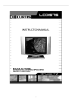
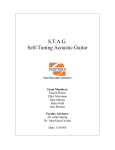
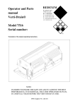
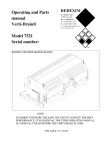
Operating Instructions Hydraulic Top link Type: GRANIT Index group 200 Operating Instructions for the GRANIT Index group 200 type Hydraulic Top link Please read and follow these operating instructions before use. Please keep them in a safe place for further use 1 2 3 4 7 8 5 6 Fig.1 Fig.2 Fig.3 Fig.4 GRANIT PARTS Limited Partnership The Knowledge Centre, Wyboston Lakes, MK44 3BY 1-16 Fig.5 Tel.: 01480 479 380 Fax: 01480 215 041 Operating Instructions Hydraulic Top link Type: GRANIT Index group 200 Index 1. EXPLANATION OF WARNINGS AND SYMBOLS IN THESE INSTRUCTIONS ..FEHLER! TEXTMARKE NICHT DEFINIERT. 2. SAFETY PROCEDURES AND ACCIDENT PREVENTION REGULATIONS ...................................................................3 2.1 2.2 3. GENERAL NOTES ON SAFETY .....................................................................................................................................................3 PRODUCT-SPECIFIC SAFETY REGULATIONS ........................................................................ FEHLER! TEXTMARKE NICHT DEFINIERT. DESCRIPTION OF USE AND SPECIFICATIONS ..............................................FEHLER! TEXTMARKE NICHT DEFINIERT. 3.1. 3.2. 4. DESIGNATED USE ...............................................................................................................................................................4 TECHNICAL SPECIFICATIONS .................................................................................................................................................5 PRODUCT DESCRIPTION...............................................................................FEHLER! TEXTMARKE NICHT DEFINIERT. 4.1. 4.2. 5.1. 5.2. 5.2.1. 5.2.2. 5.3. 5.3.1. 5.3.2. 6. INCLUDED IN DELIVERY ............................................................................................. FEHLER! TEXTMARKE NICHT DEFINIERT. DESCRIPTION AND INDIVIDUAL COMPONENTS.............................................................. FEHLER! TEXTMARKE NICHT DEFINIERT. HANDLING THE HYDRAULIC TOPLINK .......................................................................... FEHLER! TEXTMARKE NICHT DEFINIERT. INSTALLATION AND REMOVAL ................................................................................... FEHLER! TEXTMARKE NICHT DEFINIERT. INSTALLATINO ON TRACTOR ...................................................................................... FEHLER! TEXTMARKE NICHT DEFINIERT. REMOVAL FROM TRACTOR ........................................................................................ FEHLER! TEXTMARKE NICHT DEFINIERT. USING THE HYDRAULIC TOPLINK ................................................................................ FEHLER! TEXTMARKE NICHT DEFINIERT. ATTACHMENT AND USE OF DEVICES .......................................................................... FEHLER! TEXTMARKE NICHT DEFINIERT. DETACHMENT OF DEVICES ........................................................................................ FEHLER! TEXTMARKE NICHT DEFINIERT. MAINTENANCE AND CARE..........................................................................FEHLER! TEXTMARKE NICHT DEFINIERT. 6.1. 6.2. MAINTENANCE SCHEDULE ........................................................................................ FEHLER! TEXTMARKE NICHT DEFINIERT. CLEANING PLAN ...................................................................................................... FEHLER! TEXTMARKE NICHT DEFINIERT. 7. TRANSPORT AND STRORAGE ..............................................................................................................................11 8. ENVIRONMENT PROTECTION AND DISPOSAL.............................................FEHLER! TEXTMARKE NICHT DEFINIERT. 9. TROUBLESHOOTING .....................................................................................FEHLER! TEXTMARKE NICHT DEFINIERT. 10. EC CONFORMITY..................................................................................................................................................12 11. GUARANTEE.........................................................................................................................................................13 12. ADDRESS .............................................................................................................................................................13 13. OVERVIEW OF HYDRAULIC TOPLINK...................................................................................................................14 14. LEGAL INFORMATION..........................................................................................................................................16 GRANIT PARTS Limited Partnership The Knowledge Centre, Wyboston Lakes, MK44 3BY 2-16 Tel.: 01480 479 380 Fax: 01480 215 041 Operating Instructions Hydraulic Top link Type: GRANIT Index group 200 1. Explanation of Warnings and Symbols in these Operating Instructions Information in these operating instructions is identified as follows: DANGER IMPORTANT NOTE Risk of personal injury or environmental damage Risk of product damage Useful information Numbers in illustrations (1, 2, 3) correspond to the numbers in brackets (1), (2), (3) in the accompanying text and positions in tables. Procedures which must be completed in the correct order are numbered as such. Lists are identified with bullet points (●, ●). 2. Safety Procedures and Accident Prevention Regulations 2.1 General Notes on Safety These operating instructions have been produced in such a way as to ensure your safety. Personnel who are not familiar with the points made in these instructions should not be allowed to use the product. Read the entire operating instructions before using the product. Take particular note of the safety notes. These operating instructions are aimed at personnel with prior technical experience of this type of product. If you do not have experience of this type of device, seek advice from an experienced operator. Keep all paperwork delivered with this product in a safe place for reference purposes. Keep your invoice in case of guarantee claims. If the product is to be hired out or sold on, ensure that you forward all paperwork with it. Follow all maintenance schedules and care plans outlined in these operating instructions. Be aware of children, and ensure that they are not allowed to come into contact with, or play with, the product. The product may not be used after the consumption of alcohol, drugs or medication which may cause drowsiness. This product is not suitable for use by persons with reduced mental capacity, inexperienced operators or children. The manufacturer accepts no responsibility for injury or damage which occurs due to these instructions not having been read. The machine operative is responsible for injury or damage caused to third parties during operation. This product is not suitable fort he lifting or towing of objects, people or animals. The hydraulic system operates under high pressure. GRANIT PARTS Limited Partnership The Knowledge Centre, Wyboston Lakes, MK44 3BY 3-16 Tel.: 01480 479 380 Fax: 01480 215 041 Operating Instructions Hydraulic Top link Type: GRANIT Index group 200 2.2 All relevant safety regulations should be followed during the connection of hydraulic cylinders or hydraulic motors. When connecting hydraulic hoses to the tractor’s hydraulic system, ensure that the system is unpressurised. Hydraulic connections must be clearly identified to avoid the risk of incorrect connection. Check hydraulic hoses regularly, and replace if they show signs of damage or aging. Replacement hoses must conform to the manufacturer’s specifications. Where no replacement schedule is specified, hoses must be replaced after a maximum of six years to prevent aging. Use appropriate tools to prevent injury when searching for leaks. Fluid escaping under high pressure can penetrate the skin and cause serious injury and risk of infection. If injured, seek medical advice immediately! Before working on the hydraulic system, detach the product, depressurise the system and switch off the engine. Product-specific Safety Regulations Adjustment, maintenance and cleaning work should only be carried out wearing protective gloves, to avoid the risk of injury against sharp edges. Well fitting protective gloves must be worn during the operation of, and working on, the product. Carry out a visual inspection and function test before every use to avoid damage and to identify worn components. Use of the product with damaged, worn or missing components is strictly forbidden. Only pass this product on to personnel who are experienced in the use of this type of product. All relevant paperwork must also be passed on. Do not make any technical alterations to the product. Maintenance schedules and cleaning plans as set out by the manufacturer in Chapter 6 “Maintenance and Care“ must be followed carefully. Adjustment and maintenance should only be carried out by authorised, qualified personnel. Only replacement parts from Wilhelm Fricke GmbH (GRANIT) should be used for maintenance / replacement. 3. Description of Use and Technical Specifications 3.1. Designated Use !! WARNING !! The Hydraulic Top link acts as an upper mounting point for the attachment and retention of add-on devices to the rear three-point linkage of tractors. Due to the hydraulic control, mounting and dismounting of devices can be carried out from the GRANIT PARTS Limited Partnership The Knowledge Centre, Wyboston Lakes, MK44 3BY 4-16 Tel.: 01480 479 380 Fax: 01480 215 041 Operating Instructions Hydraulic Top link Type: GRANIT Index group 200 driving cab. Control of the product from the cab does not replace the requirement to check the device following attachment or detachment. In addition, it is possible to adjust the angle of the device without having to leave the cab or loosen the linkage. The hydraulic top link is not to be used for any procedure or purpose other than those outlined above. For dimensions and weight of the hydraulic top link, please see paragraph 3.2 of these operating instructions: “Technical Specifications“. For further technical enquiries please contact the sales office at Granit Parts Limited Partnership. The address can be found in chapter 12 of these operating instructions: “Addresses“. The technical requirements on the tractor where a hydraulic top link is used can be found in the Technical Specifications in paragraph 3.2 of these instructions or in the operating instructions for the tractor. Any use other than described above is strictly forbidden and constitutes nondesignated use, which can lead to serious injury or damage to property ort he environment.| RISK OF ACCIDENTS Use which exceeds the stated capacity of the product is strictly forbidden and can give rise to extreme risk of accidents with serious consequences for personnel and the environment, as well as damage to the product. All safety warnings and hints, as well as the instructions for use contained in this document must be read thoroughly. 3.2. Technical Specifications GRANIT Index Group 200 version Mechanical attachment to tractor and load capacity relating to the enclosed product (Table 2) Max. authorised working pressure: 180 bar Hydraulic connection: 1x DW push connector group 3 Medium: Mineral-based hydraulic oil HLP 46 Do not use in environments where there is a risk of explosion. GRANIT PARTS Limited Partnership The Knowledge Centre, Wyboston Lakes, MK44 3BY 5-16 Tel.: 01480 479 380 Fax: 01480 215 041 Operating Instructions Hydraulic Top link Type: GRANIT Index group 200 4. Product description 4.1. Included in Delivery Hydraulic top link partly assembled Technical documentation consisting of operating instructions to be used in conjunction with the operating instructions of the tractor. 4.2. Description and individual components WARNING: Replacement of the parts outlined in this paragraph is authorised only for qualified personnel. Incorrect use and construction can increase the risk of injury or damage. List relating to Fig. 1: No. Qty. Description 1 2 3 4 5 6 7 8 1 1 1 1 1 2 2 1 Hydraulic cylinder Warning sign Arrestor hook (according to version) Top link ball Control cable Dust cap Hydraulic hoses complete Ball joint (according to version) Table 1 Replacement parts and information about part numbers are available from your authorised GRANIT Dealer. 5.1. Handling the Hydraulic Top link Before mounting the top link onto the tractor, take note of the following points to ensure safe operation. Before installing the product onto the tractor, check the mounting points for damage and cleanliness. WARNING: Damage and cleanliness can have a negtive effect on the safety of the product. RISK OF ACCIDENT!!! Check the connection material for trueness and integrity. WARNING: Use only the connection materials delivered with the product. Where the connection material is damaged, it should be replaced with parts from GRANIT Parts. RISK OF ACCIDENT!!! GRANIT PARTS Limited Partnership The Knowledge Centre, Wyboston Lakes, MK44 3BY 6-16 Tel.: 01480 479 380 Fax: 01480 215 041 Operating Instructions Hydraulic Top link Type: GRANIT Index group 200 Check the product specifications against the details given in these operating instructions. WARNING: The use of unsuitable or defective tools can lead to injury or accident. RISK OF INJURY WARNING: The installation of the product should only be carried out by qualified personnel. RISK OF ACCIDENT!!! 1. Remove all components from its packaging and lay on a clean, robust surface. WARNING: The use of defective components can lead to injury or accident. 2. Install the control cable as per Fig.4 3. Connect the hydraulic hoses to the hydraulic cylinder (Fig.1). WARNING: Tighten hose connections fully. Escaping hydraulic fluid can lead to serious injury. 4. Install the handle (Fig.1 / optional) according to the relevant instructions. 5. Check the work completed so far and make adjustments where necessary. 5.2. Installation and Removal WARNING: Before installtion, the tractor must be protected against unintentional starting. RISK OF ACCIDENT!!! 5.2.1. Installation on Tractor 1. Check that the mounting points on tractor and product match exactly. In case of doubt, seek professional advice. WARNING: Connection on parts that do not match exactly increase the risk of accidents. 2. Make the connection between the tractor and the hydraulic top link according to the operating instructions for the tractors. 3. Connect the hydraulic connections to the tractor hydraulic system according to the operating instructions of the tractor. WARNING: Badly made connections can burst and cause increased risk of injury or damage to the environment. IMPORTANT: Low fluid levels (e.g. due to leakage) can lead to damage to the tractor’s hydraulic system. Check the fluid level before use. Refer to the technical specifications of the tractor. GRANIT PARTS Limited Partnership The Knowledge Centre, Wyboston Lakes, MK44 3BY 7-16 Tel.: 01480 479 380 Fax: 01480 215 041 Operating Instructions Hydraulic Top link Type: GRANIT Index group 200 4. Check the connections for correct seating and sufficient movement in relation to the tractor components (Fig. 3). IMPORTANT: Insufficient movement can lead to damage to the tractor and the hydraulic top link. The hydraulic cylinder may only be loaded in a straight line corresponding to the stroke of the hydraulic cylinder. IMPORTANT:. Never place tangential loads on the hydraulic top link, as this can cause damage and constitutes non-designated use. 5. Protect the top link from uncontrolled twisting, according to the operating instructions of the tractor. WARNING: When incorrectly secured, the top link can twist around, causing injury. 6. Where twisting has occurred, reset the position carefully. 7. Bleed the cylinder unit through repeated extension and retraction of the piston rod. WARNING: Do not touch the moving piston rod, as this can cause serious injury, including severe bruising up to amputation. 5.2.2. Removal from Tractor 1. Completely retract the piston rod. IMPORTANT: Ensure that the exposed piston rod is not damaged – this can lead to oil leakage and further damage to the top link. 2. Depressurise the hydraulic system, and then break the hydraulic connections between the tractor and the top link. WARNING: Pressurised fluid can escape, causing severe injury. 3. Close the hydraulic connections with the dust caps. 4. Fold the top link downwards, holding securely. WARNING: There is a risk of squashing between the tractor and the top link when folding the top link down. 5. Loosen the mechanical connection according to the operating instructions of the tractor. 6. Remove the top link. 7. Lay the top link on a clean, robust surface. 5.3. Use of the hydraulic top link WARNING: Before entering the danger zone, protect the tractor against unintentional starting and lower the device as far as it will go. RISK OF ACCIDENT!!! GRANIT PARTS Limited Partnership The Knowledge Centre, Wyboston Lakes, MK44 3BY 8-16 Tel.: 01480 479 380 Fax: 01480 215 041 Operating Instructions Hydraulic Top link Type: GRANIT Index group 200 5.3.1. Connection and use of a device 1. Check that the categories of the top link and the device match, and that the device is suitable for use with the tractor. WARNING: Non-matching categories can lead to serious accidents. 2. Secure the ball to the top link pin on the device. 3. Connect the mounting points to the lower arrestor hooks. 4. Pull the cable to open the arrestor hooks. (Fig. 2). WARNING: Do not allow the cable to loop around your hand or finger, as this increases the risk of squashing or amputation. 5. Set the required length using the adjustment points on the tractor. WARNING: Touching the moving parts or piston rod can lead to serious injury, including squashing up to amputation. 6. Lock the top link arrestor hooks by pulling down using the control cable. 7. Check the mechanical locking and the free movement of the control cable (Fig. 5). WARNING: Locks which are not completely engaged, or pinched cable can lead to unintentional opening of the arrestor hooks. RISK OF ACCIDENT!!! 8. Adjust the length of the hydraulic top link to achieve the required working and transport positions. 9. Lock the length adjuster to prevent unintentional movements. WARNING: unintentional movement can lead to serious accidents. 10. Check the installation according to the specifications of the device. 5.3.2. Removal of the Device 1. Lower the device onto a clean and robust surface. WARNING: Failure to do this can lead to tipping of the device and with it a risk of serious accident. 2. De-tension the arrestor hooks by adjusting the length of the hydraulic top link. 3. Pull the control cable to unlock the arrestor hooks. WARNING: Only control the toplink using the control cable, do not allow it to loop around any part of your body. Risk of squashing or amputation. 4. Hook the top link to the holding bracket on the tractor, and secure against twisting. WARNING: Insecure toplinks can twist and cause injury. 5. Retract the piston rod completely. 6. Disconnect any remaining connections between tractor and device. GRANIT PARTS Limited Partnership The Knowledge Centre, Wyboston Lakes, MK44 3BY 9-16 Tel.: 01480 479 380 Fax: 01480 215 041 Operating Instructions Hydraulic Top link Type: GRANIT Index group 200 WARNING: Protect the tractor against unintentional starting before stepping between the tractor and device. 7. After removal, detach the top link ball and store in a safe place. 8. Check that the device is stable, and that the top link is secured. 6. Maintenance and Servicing Maintenance and servicing should only be carried out by qualified personnel. The maintenance and servicing requirements outlined in these operating instructions are mandatory and must be observed. Use only original replacement and wear parts. Welding of the hydraulic cylinder or its pick-up points is strictly forbidden. When repainting, ensure that all product plates and warning signs remain visible and legible, o rare replaced with parts from GRANIT Parts. 6.1. Maintenance Schedule All components should be thoroughly checked before first use, after any alterations and at least once a year. These checks should be documented appropriately. Before each use, the operator should check the product for wear and damage. In particular the integrity of the mounting points must be checked. WARNING: Non-adherence to the maintenance schedule can lead to serious accidents and reduced performance of the product. All lubrication points should be lubricated according to the following plan using an environmentally-friendly lubricant. Lubrication schedule Grease the pins and linkages Before laying up (Winter break) After laying up After max. 20 operating hours Environmentally-friendly multipurpose grease 6.2. Cleaning Plan Clean all equipment after every use. Cleanliness when handling will ensure that equipment is protected from damage, and will extend its lifespan. If you are unable to remove dirt using a brush, we recommend using a jet of water. Do not use aggressive cleaning agents. WARNING: Never direct the jet of water onto hydraulic components, seals or bearings. This could lead to costly repairs. WARNING: Wash only in authorised areas. Grease and hydraulic oil run-off can lead to environmental damage. Please note your regional bylaws. GRANIT PARTS Limited Partnership The Knowledge Centre, Wyboston Lakes, MK44 3BY 10-16 Tel.: 01480 479 380 Fax: 01480 215 041 Operating Instructions Hydraulic Top link Type: GRANIT Index group 200 7. Transport and Storage When storing the top link long term, it should be washed and lubricated according to the specifications given in section 6. Check the condition of wear parts and that all components are correctly located. Carry out any necessary maintenance work or parts replacement prior to storage. WARNING: RISK OF INJURY due to muscle strain when lifting and carrying this product. Ensure that the top link is stored on a flat, stable surface. The storage area should be dry. Cover the top link with a clean, dry tarpaulin. 8. Environmental Protection and Disposal Separate disposal of different types of waste ensures that many materials can be re-used. This is also true of materials that can be reclaimed from the unit itself, from lubricants, packing and wear parts after the normal, expected lifespan of the product. Please ensure that you dispose of any waste material appropriately and safely. Ensure that a life-expired unit is rendered inoperative prior to disposal. WARNING: In case of doubt, please seek professional advice relating to removal and disposal. RISK OF INJURY! WARNING: Hydraulic fluid can be damaging to health. When working with it, always wear protective gloves. WARNING: Do not eat, drink or smoke when working with hydraulic fluid. WARNING: Hydraulic fluid run-off can lead to environmental damage. Please store fluid only in a suitable location (i.e. with a hard-standing floor). !!! Please take note of any relevant regional bylaws!!! GRANIT PARTS Limited Partnership The Knowledge Centre, Wyboston Lakes, MK44 3BY 11-16 Tel.: 01480 479 380 Fax: 01480 215 041 Operating Instructions Hydraulic Top link Type: GRANIT Index group 200 9. Troubleshooting Fault / Symptom Arrestor hook does not open. Arrestor hook does not close. Oil leakage at the piston rod. Hydraulic connector cannot be plugged in. Cause of fault Top link is not detensioned Dirt or corrosion in release mechanism. Component damaged (e.g. spring) Dirt or corrosion in locking mechanism. Component damaged (e.g. spring) Seal damaged System is pressurised. Connector damaged Piston rod does not fully extend / retract. Piston rod does not fully extend / retract. Piston rod bent or damaged Pressure is too low, or load is too heavy Control block is defective. Solution De-tension top link using tractor hydraulics. Clean according to instructions and spray with penetrating fluid. Have unit repaired at a suitable workshop. Clean according to instructions and spray with penetrating fluid. Have unit repaired at a suitable workshop. Have the seal replaced at a suitable workshop. De-pressurise system according to tractor operating instructions. Have connector replaced at a suitable workshop. Have unit repaired at a suitable workshop Have pressure tested (max. 180bar). Check the weight of the device. Have block replaced at a suitable workshop 10. EU Conformity EU Conformity for machinery (EG – RL 2006 / 42 /EG) The company, Granit Parts Ltd Partnership Wilhelm Fricke GmbH Zum Kreuzkamp 7 D-27404 Heeslingen hereby certifies that the machinery hydraulic top link, lifting component for devices Type / Series identification: GRANIT Index Group 200 conforms to the machinery regulation 2006 / 42 / EG. GRANIT PARTS Limited Partnership The Knowledge Centre, Wyboston Lakes, MK44 3BY 12-16 Tel.: 01480 479 380 Fax: 01480 215 041 Operating Instructions Hydraulic Top link Type: GRANIT Index group 200 The product has been developed in accordance with the following norms: EN ISO 12100-1 A1/A2 EN 349 ISO 730 DIN EN 982 Technical documentation retained by: Mr Holger Wachholtz, Wilhelm Fricke GmbH Heeslingen, 20/03/2011 (Holger Wachholtz, Managing Director, Wilhelm Fricke & Co GmbH) 11. Guarantee The normal guarantee policy of GRANIT Parts Ltd Partnership (Wilhelm Fricke GmbH) apply to this product as set out on our sales documentation and in our general business terms and conditions. Please direct any enquiries to the sales office. 12. Addresses Sales/Parts/Enquiries/ Customer Service: Tel.: 01480 479 380 Fax: 01480 215 041 [email protected] www.granit-parts.co.uk Postal Address: GRANIT Parts Limited Partnership The Knowledge Centre Wyboston Lakes Wyboston Bedfordshire MK44 3BY GRANIT PARTS Limited Partnership The Knowledge Centre, Wyboston Lakes, MK44 3BY 13-16 Tel.: 01480 479 380 Fax: 01480 215 041 Operating Instructions Hydraulic Top link Type: GRANIT Index group 200 13. Overview o hydraulic top link The following tables Table 2 (a) to (d) give information about the technical specifications of the hydraulic top link variants within GRANIT Index Group 200. Oberlenker beidseitig mit Kugelgelenk nicht verstellbar Best.-Nr. Gewinde Kat. A Kat. B 20003001 Sperrblock oben 1/19,2 1/19,2 95 30 ZylinderØ innen E 50 20000057 Sperrblock oben 1/19,2 1/19,2 160 30 50 410 570 44 3 2 20000058 Sperrblock oben 1/19,2 1/19,2 210 30 50 460 670 44 3 2 20000059 Sperrblock oben 1/19,2 1/19,2 280 30 50 530 810 44 3 2 20000060 Sperrblock oben 1/19,2 1/19,2 400 30 50 650 1050 44 3 2 20000061 Sperrblock oben 1/19,2 1/19,2 225 35 63 500 725 44 5 4 20003002 Sperrblock oben 2/25,4 2/25,4 95 30 50 368 463 41 3 2 20000062 Sperrblock oben 2/25,4 2/25,4 160 30 50 430 590 51 3 2 20000063 Sperrblock oben 2/25,4 2/25,4 210 30 50 480 690 51 3 2 20000064 Sperrblock oben 2/25,4 2/25,4 280 30 50 550 830 51 3 2 20000065 Sperrblock oben 2/25,4 2/25,4 400 30 50 670 1070 51 3 2 20000066 Sperrblock oben 2/25,4 2/25,4 160 35 63 450 610 51 5 4 20000067 Sperrblock oben 2/25,4 2/25,4 210 35 63 500 710 51 5 4 20000068 Sperrblock oben 2/25,4 2/25,4 280 35 63 570 850 51 5 4 20000069 Sperrblock oben 2/25,4 2/25,4 400 35 63 690 1090 51 5 4 20000070 Sperrblock oben 2/25,4 2/25,4 160 40 80 480 640 51 9 6 20000071 Sperrblock oben 2/25,4 2/25,4 210 40 80 530 740 51 9 6 20000072 Sperrblock oben 2/25,4 2/25,4 280 40 80 600 880 51 9 6 20000073 Sperrblock oben 2/25,4 2/25,4 400 40 80 720 1120 51 9 6 20003004 verstellbar, Gewinde M36 x 3 verstellbar, Gewinde M30 x 3 verstellbar, mit Gewindespindel M36 x 3 2/25,4 2/25,4 240 45 90 625 865 51 11 2/25,4 2/25,4 240 36 63 575 815 51 5 3 3 240 45 90 625 865 51 11 20003006 20003005 Hub C Kolbenstangen-Ø D F F G min. max. 352 447 44 Hubkraft (to) 3 Zugkraft (to) 2 8 4 8 Table 2a GRANIT PARTS Limited Partnership The Knowledge Centre, Wyboston Lakes, MK44 3BY 14-16 Tel.: 01480 479 380 Fax: 01480 215 041 Operating Instructions Hydraulic Top link Type: GRANIT Index group 200 Oberlenker mit Fanghaken und Kugelgelenk nicht verstellbar Best.-Nr. Ausführung 20021195 20021216 20000041 20000042 20000043 20000044 20011238 20011255 20000045 200820002 20000046 20000047 20000048 20011989 20010572 20010573 20000051 20000052 20000053 20000049 20011571 20011220 20000050 20000054 20000055 20000056 oben oben Sperrblock oben Sperrblock oben Sperrblock oben Sperrblock oben Sperrblock seitlich Sperrblock oben Sperrblock oben Sperrblock seitlich Sperrblock oben Sperrblock oben Sperrblock oben Sperrblock oben Sperrblock seitlich Sperrblock seitlich Sperrblock oben Sperrblock oben Sperrblock oben Sperrblock oben Sperrblock seitlich Sperrblock seitlich Sperrblock oben Sperrblock oben Sperrblock oben Sperrblock oben Kat. A 1 2 2 2 2 2 2 2 2 2 2 2 2 2 2 2 2 2 2 2 2 2 2 3 3 3 Kat. B 1 1 2 2 2 2 2 2 2 2 2 2 2 2 2 2 2 2 2 2 2 2 2 3 3 3 Hub Kolbenstangen-Ø C D 95 30 95 30 160 30 210 30 280 30 400 30 220 30 280 30 160 35 190 35 210 35 280 35 400 35 160 35 220 35 280 35 160 35 240 35 280 35 160 40 210 40 280 40 400 40 160 40 240 40 280 40 Zylinder-Ø innen E 50 50 50 50 50 50 60 60 63 63 63 63 63 70 70 70 70 70 70 80 80 80 80 80 80 80 F F Hubkraft G H min. max. (to) 352 447 51 19 3 362 457 51 25,4 3 510 670 51 25,4 3 560 770 51 25,4 3 630 910 51 25,4 3 750 1150 51 25,4 3 565 775 51 25,4 5 635 915 51 25,4 5 500 660 51 25,4 5 510 700 51 25,4 5 550 760 51 25,4 5 620 800 51 25,4 5 740 1140 51 25,4 5 485 645 51 25,4 6 570 790 51 25,4 6 640 920 51 25,4 6 474 634 51 25,4 6 554 794 51 25,4 6 594 874 51 25,4 6 540 700 51 25,4 9 590 800 51 25,4 9 660 940 51 25,4 9 780 1180 51 25,4 9 608 848 51 32 9 648 928 51 32 9 768 1168 51 32 9 Zugkraft (to) 2 2 2 2 2 2 3 3 4 4 4 4 4 5 5 5 5 5 5 6 6 6 5 6 6 6 Table 2b Oberlenker mit Fanghaken und Kugelkopf verstellbar, Sperrblock oben Best.-Nr. Gewinde Kat. A Kat. B 20000085 20000088 20000089 20000090 20000091 20000092 20000093 20000094 20011260 20011257 20011256 20000095 20000096 20000097 20000098 20011245 20010649 20000099 20000100 20000101 20000102 20000103 20000104 20000105 20000106 M30 x 3 M30 x 3 M30 x 3 M30 x 3 M30 x 3 M30 x 3 M30 x 3 M30 x 3 M30 x 3 M30 x 3 M30 x 3 M36 x 3 M36 x 3 M36 x 3 M36 x 3 M36 x 3 M36 x 3 M36 x 3 M36 x 3 M36 x 3 M36 x 3 M36 x 3 M36 x 3 M36 x 3 M36 x 3 2 2 2 2 2 2 2 2 2 2 2 3 3 3 3 3 3 3 3 3 3 3 3 3 3 1 1 1 1 2 2 2 2 2 2 2 2 2 2 2 2 2 2 schwer 2 schwer 2 schwer 2 schwer 3 schwer 3 schwer 3 schwer 3 schwer Hub C 240 310 240 310 240 310 240 310 240 240 240 150 240 255 200 210 240 150 240 255 200 150 240 255 200 Kolbenstangen-Ø D 35 35 35 35 35 35 35 35 36 36 36 45 45 45 45 45 45 45 45 45 45 45 45 45 45 Zylinder-Ø innen E 63 63 70 70 63 63 70 70 63 63 63 90 90 90 90 100 90 90 90 90 90 90 90 90 90 F min. F max. 637 707 637 707 657 727 657 727 585 675 585 592 692 742 652 670 645 607 707 757 667 667 707 757 667 877 1017 877 1017 897 1037 897 1037 825 915 825 742 932 997 852 880 885 757 947 1012 867 817 947 1012 867 G H 487 557 487 557 487 557 487 557 357 427 374 432 357 427 374 432 452 552 602 512 285 390 405 350 452 552 602 512 512 552 602 512 285 390 405 350 350 390 405 350 Hubkraft (to) 5 5 6 6 5 5 6 6 5 5 5 11 11 11 11 14 11 11 11 11 11 11 11 11 11 Zugkraft (to) 4 4 5 5 4 4 5 5 4 4 4 8 8 8 8 9 8 8 8 8 8 8 8 8 8 Table 2c GRANIT PARTS Limited Partnership The Knowledge Centre, Wyboston Lakes, MK44 3BY 15-16 Tel.: 01480 479 380 Fax: 01480 215 041 Operating Instructions Hydraulic Top link Type: GRANIT Index group 200 Oberlenker mit Fanghaken und Gabelkopf verstellbar, Sperrblock oben Best.-Nr. Gewinde 20000107 20000108 20000109 20000110 20000111 20000112 20000113 20000114 20000115 20000116 20000117 20000118 20000119 20000122 20000120 20000121 20000123 20000126 20000124 20000125 20000127 20000130 20000128 20000129 20000131 20000134 20000132 20000133 20010649G M30 x 3 M30 x 3 M30 x 3 M30 x 3 M30 x 3 M30 x 3 M30 x 3 M30 x 3 M30 x 3 M30 x 3 M30 x 3 M30 x 3 M36 x 3 M36 x 3 M36 x 3 M36 x 3 M36 x 3 M36 x 3 M36 x 3 M36 x 3 M36 x 3 M36 x 3 M36 x 3 M36 x 3 M36 x 3 M36 x 3 M36 x 3 M36 x 3 M36 x 3 20011240G M36 x 3 Kat. Kolbenstangen-Ø Kat. B Hub C A D 2 2 240 35 2 2 310 35 2 2 240 35 2 2 310 35 2 28 240 35 2 28 310 35 2 28 240 35 2 28 310 35 2 30 240 35 2 30 310 35 2 30 240 35 2 30 310 35 3 2 150 45 3 2 200 45 3 2 240 45 3 2 255 45 3 28 150 45 3 28 200 45 3 28 240 45 3 28 255 45 3 30 150 45 3 30 200 45 3 30 240 45 3 30 255 45 3 32 150 45 3 32 200 45 3 32 240 45 3 32 255 45 3 32 240 45 3 32 240 Zylinder-Ø innen E 63 63 70 70 63 63 70 70 63 63 70 70 90 90 90 90 90 90 90 90 90 90 90 90 90 90 90 90 90 45 90 F F min. max. 649 889 719 1029 649 889 719 1023 649 889 719 1029 649 889 719 1029 649 889 719 1029 649 889 719 1029 614 754 674 874 714 954 764 1019 614 754 674 874 714 954 764 1019 614 754 674 874 714 954 764 1019 614 754 674 874 714 954 764 1019 666 906 726 966 G H 487 557 487 557 487 557 487 557 487 557 487 557 452 512 552 602 452 512 552 602 452 512 552 602 452 512 552 602 357 427 374 432 357 427 374 432 357 427 374 432 285 350 390 405 285 350 390 405 285 350 390 405 285 350 390 405 Hubkraft (to) 5 5 6 6 5 5 6 6 5 5 6 6 11 11 11 11 11 11 11 11 11 11 11 11 11 11 11 11 11 11 Zugkraft (to) 4 4 5 5 4 4 5 5 4 4 5 5 8 8 8 8 8 8 8 8 8 8 8 8 8 8 8 8 8 8 Table 2 14. Legal information Original Operating Instructions for the Hydraulic Top link type: Granit Index Group 200. Manufacturer: GRANIT Parts (Wilhelm Fricke GmbH - D-27404 Heeslingen) 1st edition March 2011 ©2011 Wilhelm Fricke GmbH Full or partial reproduction only with written permission of GRANIT Parts Limited Partnership. All product names and models mentioned in this handbook are registered trademarks.. Printed on chlorine and acid-free paper. GRANIT PARTS Limited Partnership The Knowledge Centre, Wyboston Lakes, MK44 3BY 16-16 Tel.: 01480 479 380 Fax: 01480 215 041