1
T100si
KEY TO MAIN COMPONENTS
Fig.1
10
inside unit (fig.1)
1
Top cable entry
2
Bottom pipe entry
3
Rear pipe entry area
4
Rear cable entry area
5
Wall screw fixing
6
Terminal block
10
1
5
145
mm
6
12
11
7
4
13
7
Power PCB
8
Stabilising valve
9
Solenoid valve
10
Guide pockets
11
Can and element assembly
12
Thermal cut-out (main)
13
Earth connection
14
Outlet temperature limiter
5
8
Cover tags
17
Control PCB
Inlet
9
47
mm
14
3
Outlet
208 mm
16
Pack contents
68
mm
2
10
inside cover (fig.2)
16
338
mm
16
17
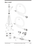
Shower unit
Four position sprayhead
Riser rail kit and fittings
Soap dish
Flexible hose
Screw fixing kit
Instructions, guarantee, etc.
16
3
Fig.2