1
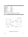
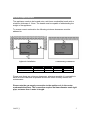
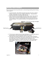
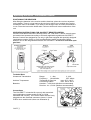
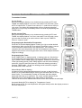
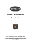
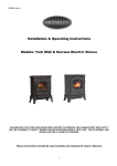
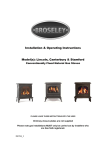
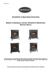
Installation & Operating Instructions
Model: York Midi
Conventionally Flued Natural Gas Stove
PLEASE LEAVE THESE INSTRUCTIONS WITH THE USER
Broseley Fires do not provide flue pipes, closure plates or any other
associated accessory.
Please note gas installations MUST only be carried out by installers who
are Gas Safe registered.
200708_3
Contents
Introduction
Packing List
Specification
Dimensions
3
3
4
4
Hearth Requirements
Chimney Requirements
5
6
Assembly
Burner Installation
Gas Connection & Pressure Testing
Positioning the Coal Ceramics
7
8
8
Spillage Testing
10
Operating the Stove
The Remote Control
11
12
Curing the Paint & Warning Notes
Trouble-shooting
15
16
Servicing Instructions
Commissioning Form
Annual Service Record
Guarantee
17
28
19
20
200707_3
2
Introduction
THANK YOU FOR PURCHASING A GAS FIRED STOVE
Broseley Fires Ltd, a family run company, was founded as an appliance and design
development company in 1975. Since then we have built up an enviable reputation for
the quality, reliability and fuel efficiency of our stoves.
These instructions have been carefully prepared to guide the installer and end-user
through the relevant methods and standards for installation of your new Gas Stove.
Correctly installed and operated, your stove will give you many years of warmth and
reliability. Therefore, we would suggest that you read the whole instruction manual prior
to handing it to your installer. That way you will have a clearer picture of what is
involved. It is required by law that the complete assembly, installation and
commissioning of gas-fired stoves is carried out by a professionally qualified and
accredited gas fitter listed on the “Gas Safe” register.
Please Note:
•
•
•
•
•
THE INSTALLATION MUST BE CARRIED OUT BY A GAS SAFE
REGISTERED ENGINEER IN ACCORDANCE WITH THE ‘GAS SAFETY
INSTALLATION AND USE REGULATIONS’ IN CONJUNCTION WITH THESE
INSTRUCTIONS.
THE RELEVANT ‘BRITISH STANDARDS CODES OF PRACTICE’
REQUIREMENTS AND THE RELEVANT ‘LOCAL AND NATIONAL BUILDING
REGULATIONS’ MUST BE ADHERED TO.
A COMMISSIONING CERTIFICATE MUST BE LEFT WITH THE END
CUSTOMER UPON FINAL COMPLETION.
THE COMMISSIONING FORM MUST BE COMPLETED IN THE BACK OF
THESE INSTRUCTIONS PRIOR TO HANDOVER TO THE END CUSTOMER.
THE PRODUCT MUST BE SERVICED ANNUALLY AND THE SERVICE
RECORD COMPLETED IN THESE INSTRUCTIONS BY THE GAS SAFE
ENGINEER.
Packing List
Stove Box
1 x Cast Iron Stove Body
1 x Box containing - 4 x Stove Legs,
Allen key and Handle
4 x Sets of Nuts, Bolts and Washers,
1 x Flue Spigot
Ceramic Box
1 x Base Coal Matrix
1 x Front Coal Matrix
1 x Rear Coal Matrix
5 x Small Loose Coals
Burner Box
1 x Burner Unit
1 x Instruction Booklet (This document)
1 x Screw & Washer (To affix gas burner in place)
1 x Remote/ Receiver
200707_3
3
Specification
Heat Input (Gross)
Max Heat Ouput
Gas Category
Supply Pressure
Gas Rate
Injector Size
Spigot diameter
Weight
Country of destination
Efficiency
6.2 kW
4.6 kW
I2H
20 mbar
0.59 m3/hr
420
125mm (5”)
65 Kg
GB, IE
Class 1
Please note this product is designed to only use natural gas.
Dimensions
All dimensions are in millimetres
200707_3
4
Hearth Requirements
The appliance needs to be located onto a solid non-combustible hearth with a
minimum thickness of 12mm. The hearth must be capable of withstanding the
weight of the appliance.
To ensure correct combustion the following minimum clearances must be
adhered to:
Inglenook Installation
Stove Clearances
Non-Combustible
Combustible
Freestanding Installation
A
75mm
N/A
B
75mm
610mm
C
50mm
610mm
Above
100mm
610mm
Please note these are minimum clearances, whenever possible it is advisable to
have as much clearance as possible around the stove for easy access and
maintenance.
Please note the gas supply connection to the appliance is in the centre
underneath the stove. The connection requires an 8mm-diameter semi-rigid
pipe, not more than 1 meter in length.
200707_3
5
Chimney Requirements
Please note Broseley Fires do not provide flue pipes, closure plates or any
other associated accessory.
The stove must be installed in accordance with current gas and buildings
regulations BS5871: Part1. The appliance can be installed in any adequate area
suitable for solid fuel fires and stoves. It can use a class 1, class 2 and pre-cast
flue.
For pre-cast flue installations it is ESSENTIAL that a sealed connection is made
into the actual flue system (a void behind a closure plate is not permitted). Please
refer to the codes of best practice for further advice on pre-cast flue’s.
Before you install the stove, make sure the chimney flue outlet is correctly
positioned to align with the flue outlet on the stove and that the chimney is in
good condition. If not, a chimney liner must be installed or a suitable class II gas
flue used. A draught is necessary to ensure the products of combustion are fully
evacuated.
Ideally it is recommended that the flue run is as straight as possible using
the top outlet on the stove. When using the rear outlet (if alignment of the
top outlet is not possible) a “T” shaped flue section should be used, the
bottom of the “T” can be capped providing a catchment area for chimney
dust/debris as well as providing a sweeping position. The flue must have a
minimum vertical height of 3 metres to insure adequate draught. You can
have a maximum of four bends in the run, each bend must not exceed 45°
and an additional metre of vertical flue should be provided for each bend.
We also recommend a minimum vertical section of 600mm before any bend
immediately off the appliance.
Prior to installation, the installer should insure that the flue is free from
obstruction and any dampers must be fixed in a permanently open position.
Ensure the chimney is not closed and that it has been swept and subsequently
smoke tested.
Make sure that rain, birds or any foreign body cannot get into the chimney to
cause damage or blockage. This problem can normally be overcome by fitting an
approved gas cowl. It is essential for the effective running of your stove that the
chimney draws properly to allow the products of combustion to escape.
VENTILATION (GB ONLY)
The gas stove is rated at less than 7kw and therefore does not normally require
additional ventilation in the room (BS5871 – part II).
200707_3
6
Assembly - Burner Installation
Ensure all components are present prior to commencing assembly (See Packing
List on page 3).
1. Unscrew the M6 x 18 Hex Bolt and open the main stove door to retrieve
the box containing the 4 Legs, Handle and Allen Key. Using the bolts
located in the bottom of the stove affix the Legs.
2. Next, with the stove stood upright insert the burner (control first) through
the door. Dip the controls through the bottom of the stove so that the
burner comes to rest on its side brackets (these prevent the burner from
moving sideways). The controls should be on the right hand side of the
stove.
Fixing point for single self tapper
Side Bracket
Side Bracket
3. Fix the burner in place using the single self tapper to connect the burner to
the rear panel of the stove (bracket located in the centre).
4. With the burner installed thread the wires running from the TTB device
(mounted on the rear panel of the stove) through the hole in the rear of the
stove and down to the 6.3mm Spade terminal connectors on the
thermocouple interrupter (Located at the rear of the Valve assembly as
shown below), These wires can be installed either way round on the
terminals.
200707_3
7
Assembly – Gas Connection & Pressure Testing
A minimum 15mm-diameter gas supply pipe must be used to within 1 metre of
the installation with the final connection to the stove to be completed with the
suitable 8mm semi-rigid gas pipe. The 8mm pipe should be connected to the inlet
of the gas valve using the nut and 8mm olive provided. Support the control whilst
finally tightening the supply pipe. A gas safety tap / restrictor elbow with a
pressure test point at the inlet to the burner is provided.
PRESSURE TESTING
Always make sure that there is adequate gas pressure and volume to the stove.
The relevant pressures are on the ID plate on the gas control knob.
1. For natural gas, this is 20mbar measured at the burner test nipple
situated at the inlet connection to the stove with the appliance in the full
rate position.
2. Ensure that the gas pressure to the stove is maintained when it is
operating at the same time as other appliances in the building and that a
suitable pressure gauge is used i.e. a manometer. Any service call as a
result of incorrect gas pressure will be chargeable.
Assembly – Positioning the Coal Ceramics
Only the ceramics supplied with this appliance should be used. The ceramics
should only be laid as described.
Replacement ceramics are available from your dealer. Whilst arranging the
ceramics, ensure that the pilot is not obstructed.
Broseley Fires Ltd accepts no responsibility for any injury sustained whilst
handling hot ceramics.
Before any ceramics are placed in position ensure that the burner is operating
correctly. The flames should be fairly even across the burners mesh top.
Ceramics which are found to be placed other than in accordance with these
instructions will result in a charge being made following any service callout.
200707_3
8
Assembly – Positioning the Coal Ceramics
Warning: Ceramic coals are very fragile so always handle with care when
fitting them. Follow these instructions carefully. Ceramics that are
positioned wrongly could seriously alter the performance of your
appliance.
Stage 1
Place largest coal matrix firmly against the
back of the stove with the three arches to
the bottom and central above the burner
mesh.
Stage 3
Place the final coal matrix on top of the
largest coal matrix and push firmly against
the back of the stove. Ensure that it is
central and the two largest coals in the
matrix are facing forward.
Stage 2
Place the smaller of the two remaining coal
matrixes in front of the previous section
with the pilot cut-out to the bottom. Then
ease the two pieces forward so that they
are a snug fit at the front.
Stage 4
Place three loose coals above the three
large coal mouldings on the largest matrix,
these coals are to be located between the
coal mouldings on the final coal matrix
(shown in Stage 3).
The other two loose coals are placed in the
depressions in front of the three large coal
mouldings of the large matrix (Shown in
Stage 1) and the front matrix (Shown in
Stage 2).
Finally, close the stove door and wind on the M6 x 18 hex bolt back onto the door
fixing bolt, slide the handle over the nut and using the Allen key supplied tighten
the grub screw onto the nut.
200707_3
9
Spillage Testing
A Spillage Test MUST be made before the installed fire is left with the customer.
Carry out the test by first closing all doors and windows in the room containing
the fire. Insure that the fire is burning at full rate for a minimum of 10-15 minutes.
Using a lighted smoke match run it along the top edge of the draught diverter on
the rear of the stove, observing the smoke being drawn into the dilution box, after
10 minutes repeat the test
If there is an extractor fan in a nearby room the spillage test must be repeated
with the fan running and all connecting doors between the fire and fan left open.
If there are still problems, the chimney / flue may require attention. Disconnect
the stove and seek expert advice.
SPILLAGE MONITORING SYSTEM
This appliance is fitted with a Temperature sensing cut out (TTB) device in the
event of the flue being blocked the device will recognise the fault as an increase
in heat inside the stove and shut the appliance down within a safe period so that
there is no excessive build up of products of combustion inside the room. This
operation would only occur if the flue path suffered severe blockage and /or
ventilation was severely impeded.
THE FOLLOWING ARE IMPORTANT WARNINGS RELATIVE TO THE
SPILLAGE MONITORING SYSTEM
1. The installer must not attempt any adjustments to the spillage monitoring
system.
2. There must be no attempt to disable the spillage monitoring system.
3. It is not possible to replace individual parts of the pilot assembly on the
appliance – only a complete pilot assembly (including thermocouple) may
be fitted in the event of a replacement being necessary. When the
spillage monitoring system is replaced, only complete and original
manufactures’ parts may be fitted.
4. Should the appliance turn itself off, wait for a minimum of 3 minutes before
attempting to re-light. In the event of your stove tripping out, consult your
installation engineer to have the flue / chimney checked.
200707_3
10
Operating the Stove
It is important to read these instructions thoroughly before lighting the
stove.
The gas stove operates with a traditional permanent pilot light.
The knobs for ignition and power control are located on the lower right hand side
of the stove.
The pilot light is located at the front middle of the coal matrix.
If the Flame Supervision Device Actuating Flame (the pilot light) is extinguished
by intention or not, no attempt should be made to re-light until 3 minutes have
elapsed.
IGNITING THE PERMANENT PILOT LIGHT
1. Depress the rear control knob fully.
2. Whilst depressed, turn knob sharply 90 degrees anti-clockwise to “pilot” setting.
Repeat until pilot light is visibly lit. You should feel some resistance and hear a
click. Repeat until the pilot lights.
3. Keep knob depressed at this point for 15-20 seconds.
4. Upon releasing, turn the knob anti-clockwise until it stops in the permanent pilot
light position. The permanent pilot light will remain lit. This is the position for
remote operation and can be left with the pilot running. You may wish to turn off
the stove during long periods of non-use perhaps during the summer months.
EXTINGUISHING THE STOVE FULLY
1. From any heat setting or the permanent pilot, depress the rear control
knob and turn clockwise to “OFF” position.
Should the glass door become broken or damaged in any way, turn your stove
off and do not attempt to re-light it. Contact your dealer for a replacement to be
fitted before relighting the appliance.
PLEASE EXPLAIN TO THE CUSTOMER THESE LIGHTING AND
EXTINGUSIHING PROCEDURES AND THAT IT IS NORMAL FOR THE
STOVE TO GIVE OFF ODOURS WHILST THE PAINT, SEALANT AND CAST
IRON MATURES.
200707_3
11
Operating the Stove – The Remote Control
POSITIONING THE RECEIVER
After fitting the batteries in the receiver and the hand set, place the receiver anywhere
on the hearth. There is a long lead on the receiver to allow you to position the receiver
towards the front of the hearth, if you wish to see the light come on when the handset is
in use. Place the lead on the hearth also. Failure to do this will cause malfunction of the
unit.
OPERATING INSTRUCTIONS FOR G30-ZRPTT REMOTE CONTROL
Caution! Read these instructions entirely before use. G30-ZRPTT remote controls must
be installed and operated according to all locally applicable regulations! G30-ZRPTT
Remote Controls are designed for use only in gas fires equipped with specially designed
combination controls (GV34 or GV36 retrofitted with a motor) produced by Mertik
Maxitrol. Due to the integrated thermostat, the G30-ZRPTT is not to be used with open
gas fires!
Technical Data
Ultrasound Transmission
Ambient Temperature
Batteries
Range:
1...10m
3...33ft.
Frequency:
ON 40,5kHz,
OFF 40kHz
Transmitter & Receiver
max. 60°C 140°F
Connecting Cables:
max. 180°C 356°F
Handset: 1 x 9V block (alkaline recommended)
Receiver: 4 x 1,5V AA (alkaline recommended)
Connections
The G30-ZRPTT is intended for use only with motorized
gas combination controls models GV34 (or GV36
retrofitted with a motor). The receiver cable must be firmly
plugged onto the flat blade connectors (motor: 6.3 and
4.8mm micro switch both 2,8mm see illustration 2).
A
200707_3
12
B
Operating the Stove – The Remote Control
Transmitter Function
Set the Display
After connecting the battery or by simultaneously pressing AUTO and
TIMER, the display flashes. You are in set mode. From set mode, press
AUTO to switch from °F (and 12 hour clock) to °C (and 24 hour clock) or
vice versa. The display will automatically return to manual mode after
some time, but you may immediately return to manual by depressing the
TIMER button.
Set the current Time
After connecting the battery or by simultaneously pressing AUTO and
TIMER, the display flashes. You are in set mode. From set mode, press
(p) to set the hour and (q) to set the minute. Wait or press TIMER to
return to “manual“ mode.
Programming the Desired Set Temperature
Press AUTO until the display flashes. Press (p) or (q) to set the desired
temperature. Wait or press AUTO to switch to automatic mode. A sensor
in the transmitter measures the room temperature. The controller
compares the room temperature with the set temperature and sends a
signal to the receiver to turn the gas valve motor, which adjusts the flame
height accordingly.
Programming the Timer
Press TIMER until P1* flashes (period 1, heating cycle on). Set the time
for the beginning of the first heating period by pressing (p) for hour and
(q) for minute. Press TIMER again; P1w appears. Set the time for the end
of the first heating period. Press TIMER again to set the second heating
period P2* (heat on) and P2w (heat off). Store both heating periods by
pressing TIMER again. • If only one heating period is desired, program
the same time for P2* nd P2w.
Manual Mode (MAN in display)
for Manual Flame Height Adjustment press (p) to turn on the fire (main
burner) or to increase flame height. Press (q) to decrease flame or to turn
down to pilot. To incrementally increase or decrease the flame height
lightly tap either the (p) or (q) button. The “send“ symbol appears in the
upper left corner of the display when either button is depressed.
The LED of the receiver flashes when knob B of the valve reaches its end stops.
Automatic Mode (AUTO in display) for Temperature Control
Briefly press AUTO. The set temperature will appear briefly before the display reverts to
the room temperature.
200707_3
13
Operating the Stove – The Remote Control
Timer Mode (TIMER in display)
• During heating periods P1* and P2*, the temperature is controlled in the same manner
as in automatic mode. When the timer program turns to w (heating cycle off), the motor
will turn the valve to pilot and there is no temperature control. This minimizes battery
consumption.
You may press AUTO to verify the set-temperature and then press TIMER to return to
timer mode.
You may press either the (p) or (q) button from any mode for manual override.
To prolong battery life, we recommend switching the transmitter to manual mode and
turning the fire to pilot with the (q) button before turning the appliance off. If the
transmitter is left in automatic or timer mode, the batteries will continue to be used when
the appliance is off.
Changing the Battery
If BATT appears in upper right hand corner of the display or if the LED of the receiver
becomes faint, please change the battery from transmitter
or receiver. If the batteries lose power, the flame height can be adjusted by manually
turning knob B (see illustration 2).
Note
Please note, the placement of the transmitter (temperature sensor) is important to
assure proper temperature regulation. Generally, a more contstant temperature will be
assured, if the transmitter is not too far from the gas appliance. Before switching to
AUTO or TIMER mode, press either button (p) or (q) to verify the reception (when the
send symbol appears in the transmitter display, the receiver’s LED must illuminate). For
the AUTO or TIMER mode to function correctly, the transmitter must remain within range
of the receiver. The transmitter should not be used in very close proximity to the receiver
(less than 1m / 3ft) as this could, in very rare cases, produce a electronic switching error.
This error could block the motor when the knob reaches the end points of its turning
radius. The knob must then be turned manually to free the blockage.
The temperature is controlled by activating the motor for a specific length of time to
adjust the appropriate flame height. This time is calculated by the transmitter and
depends on variables such as room size, heater capacity, battery power, etc. Therefore,
a few cycles are necessary before an optimum is achieved. If a low flame is sufficient to
provide enough warmth to the room, then the appliance will cycle between low fire and
off. This allows longer periods with the flame on and provides a more uniform room
temperature.
NOTE TO THE INSTALLATION ENGINEER
Please make sure the customer is familiar with the initial lighting and operating
procedures before leaving the site and that this instruction booklet is left with
them when the final commissioning is complete.
200707_3
14
Curing the Paint
It is important to note that upon initial lighting of the stove you will notice a strong
odour, this is the paint curing and is completely normal.
Most high temperature paints operate in the same way. They use a resin which
dries at room temperature and a silicon resin which cures at high temperatures.
When the stove is burned the dry resin burns away and the silicon cures. This
transition occurs at about 475°F.
Curing times will vary for each stove, we recommend leaving the fire on high for
an extended period. The house needs to be fully ventilated during these initial
burnings and although the smoke is mostly Carbon Dioxide there are other
components of the smoke which make it smell bad and may irritate some people.
These problems will go away after the paint is fully cured.
Please note switching off the appliance when you first notice the smell will
simply prolong the curing process, as recommended above the fire needs
to be left on in the high setting.
Warning Notes
We would remind you that it is a legal requirement that the stove is installed by a
qualified and accredited GAS SAFE installation engineer. Improper installation,
adjustment, alteration, service or maintenance can cause personal injury and / or
damage to property. If you are in the slightest doubt about any aspect of your
stove’s performance or you require additional information then please contact
your stove supplier, a qualified installation engineer or call our technical help-line
on 01743 461444.
Please do not store, keep or use petrol or any other flammable liquids, vapours
or substances anywhere near the stove or any other heating appliance.
We hope these instructions are clear and helpful and you are able to enjoy the
full benefits of your stove. Please keep this booklet handy for future reference.
The materials used in building your gas stove are guaranteed for one year
provided the assembly and operation complies with these instructions.
Accidental damage and all consumables including the glass door seal are not
covered.
We are sure you will appreciate and accept that our guarantee cannot be
extended to cover the assembly, installation and the use of your stove as these
are all operations outside our control or influence.
Please retain your purchase receipt. We will need to see this in the event
of a claim under warranty.
200707_3
15
Trouble-shooting
THE GAS PILOT WILL NOT IGNITE OR STAY LIT
•
•
•
•
•
•
•
•
•
Ensure the gas is turned on at the appliance and the meter / cylinder.
Hold the pilot gas button for at lest 20 seconds once the pilot is alight to
ensure the operation of the safety thermocouple valve.
Ensure that the pilot injector is not obstructed or blocked and it is free from
any dust or dirt.
Ensure that the thermocouple has not been damaged in transit. This is a very
delicate device.
On bottled gas (LPG), check that the cylinder is not empty.
Ensure that the aeration ring shutter on the pilot head is fully open so that the
pilot flame is initially intense: this can be subsequently turned down.
Ensure the pilot flame is the correct size for the type of gas. The flame
should be focused on the thermocouple probe, so that it is evenly encircled.
Any whistling sound you hear is normally caused by dirt obstructing the pilot.
This is normally cured by carrying out the cleaning process outlined in the
next section entitled Servicing Instructions.
After altering the pilot, check for any leakage of gas
THE MAIN BURNER DOES NOT SEEM TO BURN CORRECTLTY
•
•
•
Ensure there is adequate gas pressure to the appliance. The pressure can be
obtained by unscrewing the pressure test nipple and applying a suitable
pressure gauge (i.e. A MANOMETER). Be sure that the gas pressure agrees
with the identification label on your stove.
Ensure adequate volume of gas is being used. Once the fire is burning on
maximum, turn off all other gas appliances in the house and calculate the fuel
being burned from the gas meter.
See that the burner is burning evenly across the whole of the mesh surface
without any coals in place.
THE MAIN BURNER WILL NOT IGNITE OR STAY LIT
•
Ensure that the connections from the TTB to the rear of the valve assembly
are connected. If these are not connected then the burner will not light.
200707_3
16
Servicing Instructions
Servicing should be carried out annually by a qualified installation engineer when
the stove is cold and the gas supply is turned off at the isolation tap. The
following points should be checked.
•
•
•
•
•
•
Remove the coals and clean any dust and debris from the top of the burner
unit. Ideally a vacuum cleaner should be used, but a soft brush will do.
Check the condition of the coals. Any damaged ones will affect the efficient
operation of the stove and should be replaced with new ones available from
your stove supplier.
All gas supply joints should be checked to make sure they are completely
sealed and that the gas supply and pressure is to specification.
The pilot jets are correctly set and clear of obstruction.
The chimney should also be checked to make sure there are no restrictions or
blockages.
Finally re-lay the coals and re-light the stove as described previously.
200707_3
17
Commissioning Form
THIS SECTION MUST BE COMPLETED AND SIGNED BY THE
INSTALLATION ENGINEER
PLEASE LEAVE WITH THE CUSTOMER AND THE APPLIANCE.
Size of Governor setting: (i.e.) Natural Gas 20MBAR
Length and size of gas supply: _______________
Meter pressure Fire only on: ________________
All Other appliances on: __________________
Burner pressure Fire only on: _______________
All Other appliances on: __________________
Gas rate - Natural Gas - Time for 1 cubic foot in seconds: ___________
Overall length of flue: __________
Is there any spillage: __________Is the draught excessive: __________
Is there any permanent ventilation in the room: ____________________
Has the room double glazing: ______________
Is the aeration of the pilot correct: __________
Does the flame encircle the FFD: ___________
Installation Engineers Name: _____________________________________________________
Address
__________________________________
__________________________________
__________________________________
__________________________________
Post Code: ______________________________________
Telephone: __________________ Fax:__________________Mobile:______________________
Gas Safe Registration No: _______________________________________________________
Signed: ___________________________________ Date: _________________
1st service is due a
year from this date
200707_3
18
Annual Service Record
1ST YEAR SERVICE completion date:
SERVICE ENGINEER:
COMPANY NAME:
COMPANY ADDRESS:
REG. No.
.
.
POSTCODE:
CONTACT NUMBER
2ND YEAR SERVICE completion date:
SERVICE ENGINEER:
COMPANY NAME:
COMPANY ADDRESS:
..
.
REG. No.
.
POSTCODE:
3RD YEAR SERVICE completion date:
SERVICE ENGINEER:
COMPANY NAME:
COMPANY ADDRESS:
REG. No.
.
.
POSTCODE:
4TH YEAR SERVICE completion date:
SERVICE ENGINEER:
COMPANY NAME:
COMPANY ADDRESS:
REG. No.
.
.
POSTCODE:
5TH YEAR SERVICE completion date:
SERVICE ENGINEER:
COMPANY NAME:
COMPANY ADDRESS:
REG. No.
.
.
POSTCODE:
6TH YEAR SERVICE completion date:
SERVICE ENGINEER:
COMPANY NAME:
COMPANY ADDRESS:
REG. No.
POSTCODE:
Receipts should be retained for each year’s service beyond year 6
200707_3
19
Guarantee
Your decorative gas fire, when installed in accordance with the installation
instructions and operated in accordance with these instructions should provide
many years of safe and efficient operation.
We thank you for purchasing our product and trust it will provide excellent
service.
This appliance carries a guarantee of One (1) Year.
We agree to repair free of charge or, at our option, replace the appliance or part
thereof, which may prove to be defective within the guarantee period.
The guarantee is void if:
•
•
•
•
•
•
The appliance is not installed and operated in accordance with our
instructions, or
Repairs or modifications have been carried out by the purchaser or any third
party not authorised by us or:
The appliance has been misused or accidentally damaged, or
Damage is due to ‘fair wear and tear.’ or
The appliance or defective component(s) are not returned to us, prepaid
postage.
The appliance has not been serviced annually by a ‘Gas Safe Registered’
engineer.
The rights given in this guarantee are limited to the UK mainland and are in
addition to any to which you may have a statutory entitlement.
Please retain your purchase receipt. We will need to see this in the event of a
claim under warranty.
Broseley Fires Ltd
Knights Way
Battlefield Enterprise Park
Shrewsbury
Shropshire
SY1 3AB
Tel: 01743 461444
Fax: 01743 461446
http://www.broseleyfires.com
200707_3
20