1
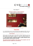
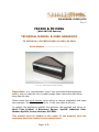
PIN NUMBER: 0558CQ1730
Rev 2
FR1500 & FR1500G
[With ANTOSS Remote]
TECHNICAL MANUAL & USER HANDBOOK
CE APPROVAL : BS EN509:2000+A1:2003+A2:2004
Serial Number ………………………………
For use with Natural Gas (G20)
Important: It is recommended, even if you have fitted these appliances
before, that you take the time to read through these instructions and follow
them step by step.
Please quote this serial number when calling to discuss installation and spare
part requests. The Warranty is valid for 1 Year from date of delivery.
To register the appliance complete the warranty card supplied and return to:
Spirit Fires Limited. 4 Beaumont Square, Aycliffe Industrial Park,
Newton Aycliffe, County Durham, DL5 6XN.
This manual must be handed to the owner of the property once the
appliance has been installed and commissioned
Page 1 of 62
Contents
Page
Page
Page
Page
Page
Page
Page
Page
Page
Page
3
4
5
6
6
7
8
9
10
12
Description
Read This First
Technical Data
Unpacking the Appliance
Parts List
Construction Drawings
Gas Burner Construction
Remote Control System
Installation Requirements
Building & Installation Work
Page 13
Page 19
Brick Built Chimney
False Chimney & Flue Liner
Page 24
Commissioning the Appliance
Page 37
Page 38
Fire Guards & Hearths
Technical : Fault Diagnosis & Troubleshooting
Page
Page
Page
Page
Page
Page
Page
Page
Page
Page
Page
Page
Page
Page
42
43
44
45
27
34
35
36
39
39
40
40
41
41
Fitting the Logs.
Fitting the Pebbles.
Final Safety Check List.
Commissioning Sheet.
Hand Set Error Codes
Typical Faults and Solutions
Pilot Assembly Explained (ODS)
Spark or Ignition Failure
Burner Flame
Remote Control Parts
Service and Aftercare Requirements
Servicing Instructions
Spare Parts / Components List
Gas Fire User Instructions
Page 2 of 62
Description of FR1500 Design
This appliance is supplied as a complete suite of gas fire burner unit, enclosure
and fascia. To comply with the approval this fire must be installed as designed.
There are two versions which can be purchased depending customer
preference. Check the data plate to confirm which version is to be installed. The
versions are:
·
·
FR1500 - This is the standard version of the fire with an overall opening
size of 175mm (H) x 1500mm (W).
FR1500G – This is a special version of the fire which has a larger opening
height of 265mm. This is then reduced down to 175mm by the addition of a
glass panel. This glass panel is an integral part of the fire and is fitted at the
factory. If it is broken it must be replaced before the fire can be used.
Refer to the Data Plate. If an FR1500G version is ordered with the larger
265mm overall opening height then it must be installed with the glass panel as
shown above.
The fire must never be operated without the glass in place. If the glass is
damaged a replacement must be purchased from the manufacturer.
Page 3 of 62
Read This First
·
·
·
·
·
·
·
·
Burner Ventilation: There is a 5mm gap between the shelf and the
enclosure. This is intentional and is used to provide burner air. Do not block
or seal this gap. With the gap blocked the fire will overheat and switch off.
Any resulting damage is not covered by the warranty. See instructions on
Page 26.
Gas Supply: Do not install the fire until the gas pipework has been checked
and a flow rate performed to ensure that the minimum flow rate specified in
the technical section can be maintained when the fire operates on full.
Failure to do this may result in the fire failing the commissioning test or
becoming unreliable. This then may require removal of the fire and pipework
to rectify the gas pressure.
§ Gas Flow Rate: Natural Gas = 1.019 m3/Hour
Room Ventilation: The FR1500 & FR1500G requires a 100cm2 free air wall
vent in the room in which it is installed.
Fascia Trim: There is an optional trim which can be fitted to the fire. Only a
trim supplied by Spirit Fires is to be used. Using a non-standard trim will
invalidate the warranty.
Gather: The gather is an integral part of the fire that is required for the fire
to function safely. It is fitted at the factory and cannot be removed. The
gather has a 180mm Spigot. If installing the fire in a brick built chimney
without a flue liner the spigot must be sealed to the chimney.
Flue System: The FR1500 AND FR1500G requires a Class 1 or 180mm flue
of minimum 2.5m length.
Flame: It is normal with this type of appliance for the flame to be directed
towards the back of the enclosure. This will be worse where the fire is
installed without the official gather and with a longer flue.
Remote Heat Shield: This fire is approved with the heat shield in place.
The fire should never be operated without the heat shield; any resulting
damage caused by heat is not covered by the warranty.
Page 4 of 62
Technical Specification
Important Note: This fire is available in two versions. Please check the
paperwork and data plate on the fire to confirm which version has been
purchased. [Read the description on page 3]
MODEL
FR1500
FR1500G
Gas Type
Natural Gas
Gas Category
I2H
Gas Type
G20
Inlet Pressure (mbar)
20
Countries of Destination
See Table Below
Gas Valve Control Unit
TESC01 RF 868-15
TESC Setup Code
228407
Remote Transmitter Type
RF868D
Injector
Stereomatic - “600” x 2pc (AC061)
Oxypilot
ERTA - PG-82-650 (AC012)
Gas Connection
8mm
Appliance Mass
40kg
Gas Rate, (Gross, kW) FULL
10.7kW
Gas Flow Rate (m3/h)
1.019 m3/h
ENCLOSURE
Enclosure Opening (mm)
Mimimum Flue
Requirements
Using Flue Liner
Minimum Chimney
Requirements
Room Air Vent
Required
Room Vent
Size [free air]
FR1500
FR1500G
1500 (w) x 265
(h) x 317 (d)
*see note below
177.8mm diameter with 2.5M length or Class 1
Chimney
1500 (w) x 175 (h) x
317 (d)
Class 1 Chimney
YES
100cm2
The FR1500 is CE approved for installation in the following European Countries with I2H
Gas @ 20mBar. AT, BG, CH, CZ, DK, EE, ES, FI, GB, GR, HR, IE, IT, LT, LV, NO, PT, RO,
SE, SI, SK, TR
*FR1500G is a special version of the fire with a glass panel at the top to give the fire the
appearance of a larger opening size however the actual opening is 175mm. This version must be
specified when ordering.
Page 5 of 62
Unpacking the Appliance
Carefully examine the carton for damage before proceeding. If it is obviously
damaged, please contact supplier to discuss whether to proceed.
Please check your delivery note. Any missing parts must be notified within 48
hours of delivery and prior to installation.
If the carton is undamaged remove the gas fire from the packaging and
examine its general condition. If satisfied by the condition, proceed with the
installation. Please note no claims will be accepted for any damaged
components once the appliance has been installed.
Read this installation booklet fully before starting to install the appliance.
Special note should be taken to the different installation requirements of the
two versions (FR1500 and FR1500G). Check the delivery paperwork and Data
Plate inside the fire to confirm which version was purchased by the customer.
The installation should only be carried out by a GAS SAFE registered engineer,
and in accordance with national and local regulations for gas. The installation
must also be in accordance with relevant parts of local and national building
regulations. Failure to have the fire fitted by a qualified person nullifies ALL
warranties and guarantees and may render the appliance dangerous.
For the Republic of Ireland, reference should be made to IS813 and ICP3 and
any guidance notes from Bord Gais.
FR1500 & FR1500G Parts List
Parts List
·
·
The Gas Fire is supplied as a Kit:
o Steel Enclosure with Gather.
o Front Vanity Cover/Shelf.
o Gas Burner with Remote Control [pre-fitted]
o Instruction Booklet
o Remote Control Handset
Optional Parts [if ordered]
o Fascia Trim.
o Ceramics – Logs or Pebbles
o Manual Wall Switch [See supplement]
o Convert from Battery to Mains Supply [see supplement]
Page 6 of 62
Construction Dimensions
FR1500
FR1500G
Page 7 of 62
Gas Burner Construction
Use
the
The
this
the image below to review the burner construction taking note of
positions of the main components and the required connections.
burner bar is pre-fitted to the enclosure. There is no reason why
should ever be removed.
Before starting to install the appliance review the Data Plate fitted to the
appliance for the gas type and pressure requirements of the appliance. Ensure
these are correct for the property supply.
This Fire has a battery remote control system and requires only the connection
of an 8mm gas supply. The remote is operated by a radio frequency remote
system with handset.
All Spirit gas fires are given a 100% full function test at the UK factory before
being shipped. We record over 40 test settings to ensure the fire operates
correctly and inline with the CE approval document.
There are no adjustable parts on this fire. Never remove any wires
from the black box or the remote system. All connections are required.
DO NOT DISMANTLE THE FIRE AS IT WILL INVALIDATE THE
WARRANTY.
Page 8 of 62
Remote Control System
Take some time to learn about the remote system fitted to this fire.
The remote system features an RF (radio frequency) handset. The handset and
the remote black box must be matched together to work correctly. Read the full
section later in this manual to ensure you understand how the remote system
works. The handset with a screen will also show any error codes which occur.
The Handset is powered by 2 x AA batteries; the Main remote system has 3 x
AA batteries. Always use high quality alkaline batteries to ensure a long life and
reliable performance. The batteries will last a minimum of 12 months or longer
however it is advised to ask you gas installer to replace the batteries on each
12 month service. The handset will switch the fire on/off and regulate the flame
up/down. The hand set has a child safe feature to avoid accidental lighting. YOU
MUST HOLD THE HANDSET IN THE PALM OF YOUR HAND TO SWITCH ON THE
HANDSET. THIS IS INDICATED BY A GREEN LIGHT ON THE RIGHT HAND SIDE.
Please read “lighting the fire” section later in this handbook before operating
the appliance.
HELP IS AVAILABLE
There are videos on YouTube that can
be used to help you set up and use
this remote system. Search on
YouTube for “TESC GAS CONTROL”
and you will find a series of
instructional videos on how to set up
and use the hand set.
Page 9 of 62
Installation Requirements
This gas fire is intended for decorative purposes. The installation must be in
accordance with National Regulations and must be carried out by a qualified
Gas Safe Registered installer. Building work should only commence after a
thorough survey of the intended location of the impending installation has been
completed and it has been established that the unit can be installed and
operated without risk to the owner or tenants of the property or their
neighbours.
This fire must be installed and used in accordance with these instructions.
Prior to installation, ensure that the local distribution conditions (identification
of the type of gas and pressure and the adjustment of the appliance) are
compatible.
Clearances between the fire and all combustible materials must conform to
National Regulations. The builders opening or fireplace opening must be
constructed of a non- combustible material.
For some countries a non-combustible hearth must be fitted in front of the fire
in accordance with National Regulations (e.g. United Kingdom).
Before the fire is installed a flue test in accordance with National Regulations
should be carried out. Any flue damper plate or flue restrictor must be
removed or fixed permanently in the fully open position, or shall only be fitted
in accordance with National Regulations.
Where existing chimney systems are to be used in conjunction they should
have been swept and undergone thorough examination to ensure that they are
in a sound and safe condition, as well as providing an adequate draw when the
gas fire unit is in operation. A simple smoke test will reveal whether or not the
chimney is working correctly. If the chimney has been used with a solid fuel
appliance in the past it must be swept before the appliance is installed. The
unit must not be installed unless the chimney/flue length is at least the
distance indicated on page 5 (minimum flue height). The fire and flue system
should be checked regularly to ensure that it is free from obstruction.
Check gas pipe work to ensure the correct flow rate for the appliance.
The minimum flue requirements for the FR1500 & FR1500G is a Class 1
Chimney or 177.8mm flue liner of minimum 2.5m length. The enclosure and
flue must be sealed in line with building regulations.
This fire is approved for use with Natural Gas Only.
Once installed all additional gas inlet holes in the enclosure must be sealed
with metal tape to avoid flame reversal which will damage the remote.
Page 10 of 62
It is important that the gas supply is disconnected before any old
existing surround and hearth is removed.
The gas connections must be in accordance with National Regulations. An
isolation valve, or valves, has to be fitted adjacent to the appliance which,
when closed, allow(s) the complete burner and control assembly to be
disconnected for maintenance or repair in accordance with National
Regulations. This is supplied with the fire.
The pilot light and flame sensing device fitted to this fire is also an atmosphere
sensing devise. If for any reason any part of the pilot assembly is to be
replaced ALL the assembly including the pilot burner, thermocouple, electrode
and injector must be exchanged complete for an original manufacturer’s pilot
assembly only. This atmosphere sensing devise is not adjustable and must not
be put out of action. The pilot light shuts off both the main burner and pilot if
evacuation of the combustion products is interrupted. If the fire shuts itself off,
do not use the fire, and have the flue and fire checked by a suitably qualified
person.
The FR1500 & FR1500G the gas fire requires an air vent within the room
which will provide a minimum of 100cm2 free air in accordance with National
Regulations. In some countries additional ventilation may be required
It is recommended that a guard be used for the protection of young children,
the elderly or infirm.
A qualified Gas Safe Registered engineer should service the fire at least every
12 months. This will ensure the fireplace operates safely.
After installation, the chimney should be inspected and swept regularly to keep
the flue clear and free from debris and excessive build up of soot. The fire
needs to be covered up when work is undertaken, to ensure the unit does not
get damaged or gas outlets blocked.
Do not throw rubbish on the unit, as this will render the appliance highly
dangerous.
Due to the newness of the materials, the fire may give off a slight smell for a
period of time after commissioning. This is quite normal and any odours should
disperse within a few hours of operation. Do not operate the appliance if
decorating or using scented candles. The particles will be drawn into the
fireplace and burnt causing staining and further smells.
Page 11 of 62
BEFORE STARTING TO INSTALL CHECK:
1. Gas Pipe Work: is it strong enough to supply this high power appliance?
Did you check the flow rates as shown on page 5?
2. Air Ventilation: Make sure an air vent is installed in the room to provide
fresh air from outside. The air vent must supply a minimum of 100cm2 air
in to the room. Check with the vent supplier. Spirit Fires can supply a high
quality air vent with baffles. Call sales on 013254-301020.
3. Chimney: Does the chimney or flue system meet the minimum
requirements as set out on page 5? Has the chimney been swept and
checked for leaks?
Building and Installation Work
Gas Supply
Consult the Data Plate within the appliance to ensure the correct gas type and
pressure is available within the property. Before commencing to create the fire
opening for the inglenook unit note that a gas supply is required. The gas
supply pipe should run into the installed enclosure from either the rear, left or
right hand sides, the gas supply is best run through the right side of the
enclosure. CHECK GAS SUPPLY RATE BEFORE INSTALLING (SEE PAGE 5)
The fire has an 8mm inlet via an isolation valve. The fire also includes a
pressure test point elbow to test inlet pressure. The gas pipe work should be
routed into the enclosure via the available access holes. If the gas pipe work is
over 1.5mtrs in length it is recommended that the pipe work is increased in
diameter from this point to 15mm, 22mm and possibly 28mm depending on the
length to the meter – see technical section for gas consumption. This will
ensure a stable gas supply.
Building Work
It is important that the gas supply is disconnected before any old existing
surround and hearth is removed. Measuring from the floor surface, the intended
location of the base of the enclosure unit is marked onto the wall. Allowances
must be made for the steel gather, if required.
The enclosure should be located centrally to the existing flue/chimney at your
desired height. If the fire is not placed central to the chimney, the flame picture
may pull incorrectly. The area indicated on the wall must be removed to house
Page 12 of 62
the Fire enclosure and burner unit. In some installations it may be necessary to
install a small lintel above the opening, if so an allowance must be made to
accommodate this lintel. (The Fire does not have its own lintel). After removing
the excess brickwork to the required height, the base of the fire opening (which
the Fire burner and enclosure will sit upon) has to be built.
To create a seal around the appliance and allow correct operation of the flue,
the original fire opening must be closed using bricks or blocks, infill the void
around the enclosure using block work or rubble. (It is advisable to install a
solid base inside the fire opening to sit the steel framework supporting the
burner unit on to.)
Installation Style:
The fire is supplied with the gather fitted, this must not be removed. The fire
can be used within an existing chimney/fireplace opening or within a new build
with a false chimney breast. Choose the correct installation method as shown
below.
1. Within a Chimney/Fireplace Opening – See Below
2. In a New Build with False Chimney Breast – Go to Page 19
Installing within a Brick Chimney
Preparing the Fireplace Opening
The above image shows the minimum fireplace opening width and
height.
Page 13 of 62
The image shows the fireplace opening required to install the fireplace unit. The
gather is fitted to the fire and cannot be removed hence there is a larger
opening height.
Above shows the minimum depth of the wall and the maximum lintel size when
fitting the fire to allow the spigot on the gather to line up with the chimney.
Add 20mm to this for the front face of the finished wall (plaster board).
The enclosure can be deeper however any voids should be filled otherwise there
is a risk of “banging” when the enclosure expands and contracts with heat.
Inserting the Fireplace into the Opening.
Once the fireplace opening has been created the appliance can be lifted into the
opening. Feed the gas pipe through the chosen hole into the lower burner area
ready for connection later. Before the gas pipe can be fed into the enclosure the
vanity cover must be removed. Ensure that this is stored in a safe place with
the screws. See image blow in how to remove the vanity cover:
Page 14 of 62
Fireplace Clearance
The fire must sit forward 20mm from the brickwork. This is for the plasterboard
that will be added later to finish the installation and create a letterbox style.
Position the enclosure in the opening so there is a minimum clearance of 10mm
on each side and 10mm at the top. This allows minor adjustment. This void
should be sealed with a suitable fire retardant material to seal the enclosure to
the opening.
Once installed in the opening the fire must be fixed down to the fireplace
opening using screws and plugs. This can be done by removing the vanity cover
and drilling through the base. Take care not to damage the connections or gas
pipes while drilling.
Page 15 of 62
The above shows the fire correctly positioned - spigot in line with the chimney.
The enclosure must sit 20mm forward of the brick wall to allow for plasterboard
to be added. See image above.
Note: The FR1500 and FR1500G are supplied with the gather fitted and sealed
to the enclosure. This gather must not be removed or modified in any way. The
gather is an integral part of the structure of the fireplace design.
Page 16 of 62
With a Flue Liner within a Brick Chimney
The flue liner must comply with the minimum size as specified in the technical
section on page 5. The liner must be sealed to the spigot.
Once the fire is fixed in place the void above the fire must be filled in as shown
below ready to be finished with plasterboard to create the final look required.
Page 17 of 62
Complete the Installation by adding plasterboard.
The gas can now be connected and the fire commissioned. Go to Page 22
Page 18 of 62
Installing in a New Build with Flue Liner
The gas fire can be installed in a new build property that does not have a built
chimney. This requires the fire to be connected to a flue liner and a false
chimney breast built around the fireplace to complete the final letterbox look. If
considering this installation method consideration needs to be given to
clearances to combustible materials. The Firebox, Gather and Flue Pipe will get
very hot. Check building regulations for guidance.
Choose Installation Location.
The firebox must be located on a flat even surface which can support the
weight of the fire and the flue liner. A breeze block wall should be built for this
purpose. Ensure there is a clearance of 20mm at the front of the wall for the
final plasterboard.
Page 19 of 62
Connect the Flue Liner
Ensure the liner meets the minimum requirements of the fire (see page 5). It is
likely that with this style of installation the flue liner should be insulated.
Contact your flue supplier for advice.
Build the Stud Wall.
Ensure the materials used are fire retardant and in line with current building
regulations.
Page 20 of 62
Add the Plaster Board
Ensure the materials used are fire retardant and in line with current building
regulations.
Page 21 of 62
Connecting the Gas.
If it has been refitted, remove the vanity cover as shown below.
The gas line should now be connected to the 8mm inlet isolation valve with
built in test point. Once connected perform a drop test to ensure no leaks in the
pipe work up to the gas appliance. Remove the heat shield to gain access to the
remote control unit so that the power switch put in the “on” position.
Page 22 of 62
Once the heat shield is removed the remote control is visible. Remove the
shield from the remote box and switch on the power.
Refit the remote heat shield pocket.
Refit the metal heat shield.
Read the section on lighting the fire and how to operate the remote
control - Read Page 48.
The fire is now ready to be commissioned.
Page 23 of 62
COMMISSIONING THE APPLIANCE
WARNING: The burner inlet flow rates are factory set and cannot be changed.
The aeration is fixed; do not change the burner aeration. This fire must not be
operated without the heat shield in place over the remote system. Failure to do
this will result in serious damage to the remote system which will not be
covered by the warranty.
The burner is tested to 150mBar at the factory to ensure there are no gas leaks
in the burner. Do not adjust any fixings within the fire.
Refer to the “lighting the fire” on page 48 later in this handbook to learn the
remote system and sequence.
To commission the appliance complete all of the steps below.
CHECK THE GAS PRESSURE
· Use the commissioning sheet on page 36 completing each
section in turn, recording the gas pressures measured on the
sheet.
· It is very important that this test is performed as stated to
ensure the appliance is safe and reliable.
· Ensure the gas tap is in the open position to allow gas to flow. Remove
the screw from the test point within the appliance and connect a
manometer. With the appliance off check for gas soundness in the
supply circuit. If there is a pressure drop correct the leak in the pipe
work before continuing.
· Check 1 – Record the standing pressure in the commissioning
sheet.
· Using the handset start the fire. The pilot will light and then the main
burner will ignite. If the pilot does not light try a few times until any air
in the gas pipes has been purged.
· Use the handset to ensure the fire is on full. You will now start a set of
tests which will confirm the gas pressure is within the safety limits.
· The inlet supply pressure (measured at the test point in the fire)
must be within (+/- 1mb) of the pressure stated on the Data Plate. For
example a 20mBar Natural Gas appliance must read between 19mbar
and 21mBar.
· Check 2 – with the fire on full and all other gas appliances in the
home on - record the pressure in the commissioning sheet.
· Check 3 – with the fire on full and all other gas appliances in the
home off - record the pressure in the commissioning sheet.
· Are the results within the limits?
Page 24 of 62
·
IF THE TEST IS FAILED: If it is not possible to maintain the pressure
at the required level the problem may be caused by blockages in the
pipework, incorrect pipe sizing or a faulty meter. If the problem is the
meter then TRANSCO, BORD GAIS or the propane supplier must be
called to adjust the governor. Do not use the appliance until the issue is
rectified.
·
IF THE TEST IS PASSED: Disconnect the pressure gauge, replace the
pressure test point sealing screw and test the appliance for gas
soundness. Refit the front shelf.
Page 25 of 62
Warning: Front Shelf & Burner Ventilation
The front shelf when fitted correctly has a small 5mm gap below it to allow air
into the burner tray.
DO NOT BLOCK THIS SLOT OR SERIOUS DAMAGE WILL OCCUR TO THE
REMOTE SYSTEM.
Once the shelf is correctly fitted:
Fit the Ceramics to the Fire
The fire can be operated as a Ribbon Flame Only or either Fireplace Logs or
Pebbles depending on the customer purchase order. If in doubt before
proceeding check with the customer which version was purchased.
Warning: Only the ceramics supplied with the fire can be used.
The ceramic logs and pebbles must be positioned on the burner as shown in the
following set of images.
Page 26 of 62
FR1500 – Log Set Layout (19 Piece Set)
Add Log - #15
Add Log - #6
Add Log - #3
Page 27 of 62
Add Log - #3
Add Log - #10
Add Log - #14
Page 28 of 62
Add Log - #8
Add Log - #6
Add Log - #15
Page 29 of 62
Add Log - #5
Add Log - #13
Add Log - #11
Ceramic Wool : using latex gloves – make the ceramic wool into
strands and place this on the burner bar. This will create a sparkling
effect when the burner is lit.
Page 30 of 62
Add Log - #4
Add Log - #8
Add Log - #17
Page 31 of 62
Add Log - #14
Add Log - #16
Add Log - #10
Page 32 of 62
Add Log - #9
FINAL LAYOUT
LEFT HAND SIDE
RIGHT HANDSIDE
Page 33 of 62
FR1500 – Pebble Set Layout (45 pebbles)
The fire is supplied with 45 pebbles of various colours. These are arranged with
23 Pebbles along the back, 22 pebbles along the front. The pebbles must not
touch the burner and are positioned on the vanity cover. See images below.
Add the Wool between the pebbles and along the burner bar. Do not place any
wool near the pilot assembly. The wool should only be in the centre section.
Refit the Vanity/Shelf
The vanity/Shelf is secured by 4x cross headed screws. These must be fitted
and the shelf fixed in place. WARNING: If the shelf is left loose and the fire
used the vanity will be damaged by the burner flame and the remote system
will over heat and become damaged. The warranty is void if the fire is used
with the shelf not fixed in place by the screws.
Page 34 of 62
Commissioning Continued……
Check the Flue System
·
Turn the appliance to the maximum setting (full rate). Leave the
appliance for 10 minutes and then test that all the products of
combustion are entering the flue by traversing the perimeter of the
fireplace opening or canopy using a smoke generator e.g. smoke
matches. If the appliance passes this test then it can be signed off. If the
test is failed leave the fire for a further 10 minutes and test again. If it
still fails, disconnect the gas and do not use the appliance until the
problems with the chimney/flue liner have been rectified.
Complete the Installation
·
·
·
·
·
·
Complete the commissioning sheet on page 36.
Give the installation booklet to the customer.
The customer should be shown in detail how to operate the appliance and
the installation and user manual given to the customer.
The customer must also be made aware that the appliance must be
serviced every 12 months and that chimney or flue system should be
checked regularly to ensure the appliance operates at optimum
performance.
The customer must be told not to block the room air vent.
The warranty card is to be completed by the registered engineer who has
commissioned the appliance. This is to validate the warranty. The card
must then be given to the customer for postage back to the factory.
GAS ENGINEER - FINAL SAFETY CHECK
·
·
·
·
·
·
·
·
Is the inlet pressure, checked at the inlet point inside the fire,
within the 21mBar to 19mBar limits when the fire is on full?
Is the flue/chimney operating safely?
Are the flue/chimney and enclosure sealed?
Are all gas inlet holes in the burner tray sealed with metal tape?
Are all the heat shields fitted?
Is there a minimum of 100cm2 air ventilation?
Has the customer being shown how to operate the appliance?
Has the customer been shown how to replace the batteries in the
handset and the main appliance?
If you have any questions, or the gas fire is not operating correctly, contact the
manufacturer on 01325-327221 before you leave the installation. If the
appliance is to working correctly it should be disconnected from the gas supply
until the problem is rectified. If the appliance is not fitted in strict accordance
with these instructions, Spirit Fires cannot be held responsible for any damage
caused and reserve the right to charge for any corrective work.
Page 35 of 62
Commissioning Checklist
This product is guaranteed for 1 year from the date of delivery, as set out in the terms
and conditions of sale. This guarantee will be invalid, to the extent permitted by law,
if the above Commissioning Checklist is not fully completed by the installer.
Installation Company…………………………………….………………………………………………..
Engineer………………………………………………………………………………………………………………
Contact No…………………………………………………………………………………………………….……
Gas Safe Number………………………………………………………………………………………………
Date of Installation…………………………………………………………………………….……………
Flue Check
Reading
Pass
Fail
1. Flue is correct for appliance
2. Flue Flow test
3. Spillage test
Gas Check
1. Gas soundness & let by test
2. Standing pressure test (appliance off)
…………..mBar
3. Appliance working pressure (on High Setting)
with all other gas appliances in the house
operating on full.
…………..mBar
4. Appliance working pressure (on High Setting)
with all other gas appliances in the house
switched off.
…………..mBar
5. Does ventilation meet appliance requirements?
To pass the commissioning test the fire must have the correct inlet pressure “when
measured at the test point that is supplied within the fireplace”. The pressure
reading, with the fire operating on full, must be within the limits of 21mB to 19Mb. If
the appliance does not pass this test it should be disconnected from the gas until the
problem with gas supply has been rectified. This could be the pipe work or the meter.
Page 36 of 62
Warning: Fire Guards & Hearths
This appliance is not fitted with an integral guard. In normal use
consideration may be given to the use of a fireguard conforming to
BS6539 or BS6778, so that the approach to the appliance is limited
such that access to the flame is minimised
It is recommended that a fireguard conforming to BS6539 or BS6778 is used
for the protection of young children, the elderly and infirm.
The installer is to advise the user not to stand too close to the appliance for
prolonged periods of time and warn that loose clothing is particularly at risk of
burning due to the presence of an unguarded flame.
In addition, the installer is to advise the user against placing combustible
material directly in front of the appliance. Floor coverings, such as carpets, are
considered to be acceptable.
For some countries a non-combustible hearth must be fitted in front of the fire
in accordance with National Regulations (e.g. United Kingdom).
Page 37 of 62
Technical : Fault Diagnosis & Troubleshooting
Every gas fire manufactured by Spirit Fires is tested at the factory and given a
full 40 point performance check to ensure it operates correctly. It is highly
unlikely that when installed in line with these instructions that it would not
operate as designed. The most typical causes of problems during the initial
phase after installation are incorrect gas pressure and flue system
requirements. If experiencing problems go back to the installation section and
check the install step by step.
The gas pressure must be tested using the test point inside the fire and when
operating on full and ALL other gas appliances in the home are running also it
must read between 21mBar and 19mBar. Outside of these limits the fire will
shut down and be unreliable, even dangerous. Do not use the fire until the gas
pressure problem is solved. If the problem is the chimney, have a smoke test
performed to ensure it is not blocked or there is severe down draft occurring.
If the commissioning procedure is not followed and the fire is left to
run with the wrong gas pressure the fire will:
1.
2.
3.
4.
5.
6.
Fail to light.
Light for a few seconds.
Shut down unexpectedly.
Have a low flame.
Have a yellow flame.
Cause sooting in the enclosure.
Other areas to check during installation are:
1.
2.
3.
4.
5.
Has the pilot been knocked and the gap too large?
Are you using the handset properly (see YouTube for videos)
Are the batteries fitted properly?
Is the magic eye positioned correctly?
Is the flue operating correctly without reverse drafts or air leaks?
Unexpected or Sudden shutdown
If the appliance shuts down unexpectedly it highlights a fault with the
installation. If the appliance will light again within a few hours it confirms that
the appliance is working but is installed incorrectly – it could be gas pressure or
a faulty chimney that is causing the shutdown. The pilot is a safety device
which monitors the gas pressure and flue conditions. If a fault in either of these
areas are detected the pilot will not allow the fire to be lit. Please review the
installation conditions before proceeding. DO NOT USE THE GAS FIRE UNTIL A
GAS SAFE ENGINEER HAS INSPECTED THE INSTALLATION. The installation
should be checked step by step against this manual.
Page 38 of 62
Faults – Hand Set Error Codes
The handset will display an error code if a fault occurs. Refer to the separate
sheet included with the manual for a full description of why the fire has
failed.
Typical Faults & Solutions
Symptom
Appliance clicks but
no spark or weak
spark.
Possible Cause and Solution
Check spark lead is connected properly.
Check spark electrode is in the correct area and the gap correctly distanced to
the pilot.
Check for a good spark. Check the spark is in the right area.
Appliance sparks but
does not light pilot.
Check that there is gas coming through by using a match.
Check that there is not air in the gas line – purge the system.
No Gas, fire does not
light with match.
Check isolation tap/shut off is open.
Check for blockages in the gas pipes.
Check for a good spark.
If there is gas but
pilot does not light
Check the spark is in the right area.
Check that the ignition lead is connected.
Check the pilot gas slot is clear.
Check the pilot flame is heating the thermocouple – replace pilot.
Pilot lights but does
not light main burner
Check that the thermocouple is working – replace pilot.
Check that the gas pressure is strong enough. Connect a manometer and listen for
the main burner opening if the gas pressure drops there is a blockage or the pipes
are not big enough.
Check that the gas pressure is strong enough. Connect a manometer and listen for
the main burner opening if the gas pressure drops there is a blockage or the pipes
are not big enough.
Burner lights but
turns off after a few
minutes
Check for chimney draw or downdraft causing pilot to go out. (Safety Device
operating)
Check ventilation is not too strong and the flame is not blowing off the
thermocouple.
Check gas pressure is correct and maintained at constant level – especially with
other appliances in the home working.
Hand set Error Codes
The handset shows a code EXX when there is a fault. Use the chart to trace the
fault. If you do not have the chart, call 01325-327221 to request a copy. Do not
start dismantling the gas fire as further damage will be done.
Page 39 of 62
Pilot Assembly / ODS
There is a highly sensitive oxygen depletion sensor designed into the pilot light.
If any part is damaged the entire unit must be replaced. Do not attempt to
bend or alter the flame head, thermocouple or aeration hole. Use only genuine
spare parts as similar looking parts from other appliances may well give
different or inferior performance and could lead to a hazard.
Spark / Ignition Failure
The gap between the pilot electrode and the pilot should be 3.5 – 4.5mm and
normally adjustment is not necessary (the electrode is very brittle). The spark
should jump across the gap between the electrode and the gas outlet on the
pilot head. If the ignition fails, a lighted taper or match can be inserted into the
pilot area to check that gas is reaching the pilot. If the pilot lights using a taper
or match then check the ignition lead has not become detached or the pilot gap
is correct. If the problem still exists replace the pilot assembly.
Page 40 of 62
Burner Flame
The flame on this type of appliance is normally directed towards the rear of the
enclosure. This is normal due to the opening size and flue system. The flame
will never stand “upright”. It is to be expected that over time the surface on the
rear of the enclosure will tarnish. This is typical “wear and tear” for a gas fire.
If the flame is drawn under the shelf this highlights a serious installation fault
and the appliance must not be operated until the cause of the flame reversal is
found. A typical cause would be unsealed burner holes, failure to seal the
enclosure and flue, downdraft on the flue system or incorrect flue system. If the
fire is operated with flame reversal the remote will be damaged and any
resulting heat damage is not covered by the warranty.
Remote Control Components
The remote control used on this fire has only a small number of components to
function:
a) A black remote box / gas control valve
b) An ignition lead
c) A Pilot Assembly
d) A Hand Set
The remote is built to the latest standards and is new to the UK market. Take
some time to review the lighting procedure and learn about the operation of the
remote.
Remote Control – Error Codes
If a fault occurs the handset will show an error code. Use the attached sheets to
learn about the codes and how to rectify the fault displayed. To reset the error
press the power button on the handset and it will return to normal operation.
Page 41 of 62
Service and Aftercare Requirements
Every 12 months the gas fire unit should undergo a regular service; this work
should be carried out by a Gas Safe registered engineer only.
The annual service of the unit must be performed in line with the
instructions in the manual. Refer to the enclosed technical installation
and operational manual & the remote control instruction document.
When carrying out the annual service, the Gas Safe Engineer should
examine and verify the following;
·
·
·
·
·
·
·
·
Ensure the pilot assembly is clean and operates safely.
Ensure the injector is clean and fitted correctly.
Ensure the burner aeration is as per the manufacturer’s instructions.
That the gas fire burner unit correctly cross-lights within 10 seconds.
A pressure drop test to verify that there are no gas leaks
That the electronic ignition system operates correctly
That the burner surface is free from damage and debris.
That the owner has a copy of the installation and operation manual
For Spare Parts please call 01325-327221 and ask for customer
service. Spare parts are not returnable & Spirit Fires cannot accept
responsibility for incorrect parts being ordered. When ordering
replacement components or requesting technical assistance, you should at all
times quote the following:
·
·
·
Type of fire & gas type (LPG or NG) as shown on Data Plate
Unit serial number as shown on Data Plate or front of booklet.
Component part number or description of fault
Page 42 of 62
Servicing Instructions
The following servicing procedure should be carried out every 12 months and
only by a registered Gas Safe Engineer. As foreign bodies, which can gather on
the surface of the burner unit, it is inevitable that servicing can be a dusty
operation therefore suitable precautions should be taken.
Warning: The pilot assembly and flame sensing device fitted to this fire is also
an atmosphere sensing device. If for any reason any part of the pilot assembly
is to be replaced, the entire assembly including the pilot burner, thermocouple
electrode and injector must also be exchanged. This atmosphere sensing device
is not adjustable and must not be disabled. Only manufacturer supplied
parts must be used when replacing components on this fire.
Servicing Procedure
·
·
·
·
·
·
Turn off the gas fire and allow time for it to cool.
Remove the vanity cover as shown on page 14.
Turn off the gas supply at the isolation tap within the fire.
INJECTOR: Use a 15mm
spanner to remove the gas pipe
from the injectors. Using a 7mm
spanner loosen the screws on the
injector bracket and lift the
injector bracket off the venturi
tube. Clean the injector and
remove blockages. Do not use a
needle or wire, as this will
damage the injector. Clean any
debris from around the aeration
hole. Reassemble the injector
and connect the gas pipe.
PILOT ASSEMBLY: To ensure a
long reliable life it is advised to
change the pilot when servicing
the fire. This can be done by
disconnecting the gas supply,
ignition lead and connections to
the remote. Use the image below
to ensure the correct connections
are made on the remote black
box. If the pilot is not being
changed then make sure the pilot
journals are clear and free from
dirt.
BURNER: Using a soft brush or
Page 43 of 62
·
·
·
vacuum cleaner, carefully
remove any debris from the
burner unit.
FINAL STEPS: Re-assemble the
fire in the reverse order, and reconnect the gas supply and check
for leaks.
Check the pilot assembly for a
good strong flame.
The fire must now be
commissioned following all the
steps set out on page 24.
Spare Part / Component List
Part
Code
AC061
AC012
GC019
GC020
GC022
Type
Gas
Marking
Injector
Pilot
Remote Box
Handset
Ignition Lead
NG
NG
NG
NG
-
600
82-650
TESC01
FB-868D
HT380
Per
Fire
2
1
1
1
1
Engineer
Parts
YES
YES
YES
YES
YES
User
Parts
NO
NO
NO
YES
NO
Ordering & Fitting Spare Parts.
When calling to order spare parts you will be requested to provide both the
serial number of the fire and gas safe registration number of the person who
will carry out the repairs. The serial number is shown on the data plate. Call
01325-327221 and ask for Customer Services to order spare parts. We can
email a set of images to confirm the parts required. The only “user”
replacement part for this gas fire is the remote handset. All other parts must
be fitted by a trained gas engineer. The fitting of replacement parts must be
carried out by a qualified Gas Safe Engineer in line with current regulations. To
change parts refer to the servicing section of this manual.
Optional Extras
There is an option to add a wall switch and to upgrade to a mains power
supply. These parts must be ordered from customer services. The work must
be carried out by a trained gas safe engineer with electrical qualifications.
Page 44 of 62
PIN NUMBER: 0558CQ1730
Rev 1
FR1500 & FR1500G
[With ANTOSS Remote]
USER HANDBOOK
Serial Number ………………………………
For use with Natural Gas (G20)
Please quote this serial number when calling to discuss installation and spare
part requests. The Warranty is valid for 1 Year from date of delivery.
To register the appliance complete the warranty card supplied and return to:
Spirit Fires Limited. 4 Beaumont Square, Aycliffe Industrial Park,
Newton Aycliffe, County Durham, DL5 6XN.
This manual must be handed to the owner of the property once the
appliance has been installed and commissioned
Page 45 of 62
Contents
Page
Page
Page
Page
Page
Page
Page
Page
Page
Page
47
48
57
58
59
59
60
60
61
62
General Information
Start/Shutdown Instructions
Using the Manual Switch Panel
Replacing the Batteries
Cleaning Instructions
Fireplace Ceramics
Replacement Parts
Fire Guards and Hearths
Warranty Information
Contact Details
Page 46 of 62
General Information
A qualified GAS SAFE registered installer is required to fully install the
appliance, failure to do this may render the appliance dangerous and will
invalidate the warranty.
This fire is intended for decorative purposes. Any purpose-provided ventilation
should be checked regularly to ensure that it is free from obstruction. The fire
should be serviced regularly by a qualified person.
The chimney should be swept before the appliance is installed, and should be
swept and inspected regularly to ensure that all of the products of combustion
are entering the flue and there is no excessive build up of soot. Once the flue
and fire units have been checked and remedial action taken, the fire is ignited
in the manner depicted in section ‘Lighting the fire’ – see page 48.
This fire should be checked regularly to ensure that it is free from obstruction.
Do not throw rubbish et cetera upon the burner surface area or otherwise
disturb the fuel bed. Debris from any source, or soot formed, should be
removed from time to time, see ‘Cleaning instructions’ – see page 59.
Due to the newness of materials, the fire may give off a slight smell for a period
of time after commissioning. This is quite normal and any odours should
disperse within a few hours of operation. Do not use the fire when decorating or
burning scented candles. This will cause additional smells and staining on walls.
For some countries a purpose provided air supply must be fitted in accordance
with National Regulations. For the UK a 100cm2 air vent to the outside is
required to supply air ventilation to the gas fire.
A qualified person should service the fire regularly – we recommend an annual
service to ensure the gas fire works efficiently, reliably and safely.
Fire Guards: It is recommended that a fireguard conforming to BS6539 or
BS6778 is used for the protection of young children, the elderly and infirm.
Pilot Assembly: The pilot light and flame sensing device fitted to this fire is
also an atmosphere sensing device which shuts off both the main burner and
pilot flame if evacuation of the combustion products is interrupted. The most
likely cause is a blocked chimney. If the fire shuts itself off, restart the fire
following the procedure in section ‘Lighting the fire’ on page 48. If the fire
continues to shut itself off do not use the fire, and have the flue/chimney and
fire checked by a suitably qualified person. The pilots ODS (Oxygen depletion
sensor) must not be put out of operation. The user must not adjust the pilot. If
any of its parts are damaged and need to be exchanged the original
manufacturers parts must be used.
Page 47 of 62
Lighting/Adjusting the Fire
The appliance is supplied with an internal battery power supply and is operated
via a handset. There are 3 x ‘AA’ batteries inside the appliance and 2 x AA
batteries in the handset. Only use good quality alkaline batteries to ensure a
long life from the handset and remote box.
The handset comes already paired to work with the fire and the time set etc.
Please read these instructions carefully and watch the instructional youtube
video through your internet web browser if necessary. Do not try pairing the
handset thinking that it is not paired, it is more likely the handset is not being
pressed correctly.
If the main burner or pilot light is extinguished during lighting, do not attempt
to re-light the pilot within three minutes.
Quick Start User Instructions
NOTE: The following operations can be seen on YouTube,
use your internet browser to visit YouTube page and
within YouTube search for “TESC GAS CONTROL”
The remote control black box is situated within the fire. The drawing shows the
main features of the control. The control requires 3 AA size alkaline batteries to
be inserted under the battery compartment cover. The orientation of the
batteries is shown within the battery compartment. After fitting the batteries
and replacing the cover the fire can now operate. Slide the slide switch to the
right to the On position (I symbol).
Page 48 of 62
Mode – MAN( Manual), Zzz
(Snooze), thermostat or timed.
Day of the week
Time (12hour or 24 hr
display)
In Range of fire
(missing if not in
range or if Fire
Control turned off)
Gas fire burner
status
Room Temperature
Battery condition –
RC handset, FC
fire control
Handset Unlocked
when Illuminated
Light sensor
(for display back
light)
To change handset
settings (see handbook)
To change mode
(see handbook)
Press to decrease flame
Press to increase flame
Power Button – To start the fire, with one hand grasp around the rear of both sides of the button
Operating
instruction
area
control. The
green unlock light will illuminate. Keep the handset held to keep the control
Lighting
the
withofThe
Handset
unlocked, to enableFire
operation
the buttons.
Then with the other hand touch and hold a finger on
Read
First
the
powerthis
button
for about 3 seconds. (A short beep and a flash of the unlock light will happen upon
touching.) When the word “pilot” appears at the bottom left hand corner of the display, immediately
release the power button. (A second flash of the unlock light and a longer beep will also sound at the
time to release the power button). The Fire should be lit within a few seconds. ( N.B. If power
button is held for more than a few seconds after second flash/beep/word pilot appears, the command
is ignored for safety reasons. Similarly if it is released too soon before the word pilot appears, the
command is also ignored. With this system, the control has been designed to ensure that only
intended ignition of the fire occurs.). To stop the fire, hold the handset so that it unlocks, press
then release power button.
Page 49 of 62
Ensure the power isolator switch on the front corner of Fire Control Black Box
within the Fire is in the on position (I).
Note: The handset has a child safe function. To unlock the handset you
must grasp the handset in the palm of your hand. The green unlock
light will illuminate to show when the handset is unlocked and ready to
accept commands. (N.B. Keep a grip of handset to keep it unlocked, to
continue to operate the command buttons.
For safety reasons a button must be pressed and released for the command to
be recognised. Keeping hold of a button when pressing (unless otherwise
instructed) will not be recognised as a command press.
Lighting the Fire
·
·
·
·
·
·
·
·
·
The handset should be showing a Wifi symbol
in the top right of the
display. This means the handset is within range of the fire control box and
can be used to light the fire.
If the symbol is not there check:
o a) the batteries in the handset and the fire gas control box are the
correct way around.
o b) the batteries are in good condition – if in doubt fit a new set of
alkaline batteries (like Duracell).
o c) that the small isolation switch on the gas control in the top left
corner is in the ON position (I) and not the OFF position (O).
Grasp the handset in the palm of the hand and sides to unlock the child
safe mode. The green unlock light will illuminate. Keep the handset held
to keep the control unlocked, to enable operation of the buttons.
Look at the image on the previous page to identify the power button.
With the other hand touch and hold a finger on the power button for
about 3 seconds.
There will be a short beep and the unlock light will flash.
When the word “pilot” appears at the bottom left hand corner of the
display, immediately release the power button.
There will be a second flash of the unlock light and a longer beep.
The fire will start the ignition sequence and start within a few seconds.
Warning: If power button is held for more than a few seconds after the
second flash/beep & the word pilot appears, the command is ignored for
safety reasons. Similarly if it is released too soon before the word pilot
appears, the command is also ignored. This is a safety feature built into
the system to ensure the fire only lights when it is intended to by the
user.
Page 50 of 62
Adjusting the Flame
·
·
·
Grasp the handset in the palm of the hand and sides to unlock the child
safe mode. The green unlock light will illuminate. Keep the handset held
to keep the control unlocked, to enable operation of the buttons.
Look at the image on the previous page to identify the + & - buttons.
Using your other hand press the buttons to decrease and increase the
flame. Look at the screen on the handset and it will show the current
state of the flame – between Max and Min.
Switching the Fire Off
·
·
·
Grasp the handset in the palm of the hand and sides to unlock the child
safe mode. The green unlock light will illuminate. Keep the handset held
to keep the control unlocked, to enable operation of the buttons.
Look at the image on the previous page to identify the power button.
Using your other hand press and release the power button and the fire
will switch off.
NOTE: The following operations can be seen on YouTube,
use your internet browser to visit YouTube page and
within YouTube search for “TESC GAS CONTROL”
Setting Up The Handset
The handset comes paired to the black box so does not need setting up on a
new fireplace. Use this section to adjust the handset settings and to set up the
other functions.
We advise not adjusting the handset until you are comfortable with
using the handset and are able to switch the fire on/off easily. Using
the YouTube videos will resolve most issues to do with lighting and
setting up the fire as the process is shown visually
Battery Condition Display
The legend at the bottom of the screen shows the battery condition of both the
batteries in the hand set and in the fire control unit.
RC = Remote Control handset.
FC = Fire Control Box (inside fire).
If the batteries are exhausted the fire will not work. To get the best
performance from your fire we recommend using high quality alkaline batteries
and we suggest these are replaced by your gas engineer each year during the
annual service. N.B. Pairing is not lost, even if the batteries are removed or flat.
Page 51 of 62
Setting the Time
Should you have to set the time or change the time you need to enter the
SETUP menu. Hold the handset to unlock the keypad and keep held throughout
the following steps, (if you release too soon the menu will exit and you will have
to start again). Press and hold set for several seconds. The symbol in the top
centre will flash. Press and release the “mode” button several times until the
word “SETUP” appears flashing in the top right corner of the display.
Press and release “set” again to enter the “SETUP” menu.
Here you can change the clock from 12 hr or 24 hour format, the day of the
week, hour of the day, minute of the day and the display in Celsius or
Fahrenheit.
To navigate through the menu “set” moves to the next parameter and
“Mode” move back to the previous parameter. “+” and “-“ change the
display parameter.
Setting the display for 12 or 24 Hour display
The H indicates that it is time to set the timer to either 24
hour display or 12 Hour (AM or PM ) display. Press the + or
– button on the handset to toggle between the two settings.
When you are ready to confirm the setting you want press
the “SET” button to progress to setting the day of the week.
Setting the day of the week
Press and release the + and – buttons until the correct day of
the week is shown on the display.
(Mo = Monday, Tu= Tuesday, We=Wednesday, Th=Thursday,
Fr=Friday, Sa= Saturday and Su=Sunday).
Press “SET” to accept the day of the week and to progress to
setting the Hour of the day.
Note: Whilst doing this setup pressing “SET” advances to the
next display and pressing “MODE” will return you to the
previous display setting.
Page 52 of 62
Setting the Hour
Press and release the + or – button to change the hour to the
correct hour and press set to store and to move to setting the
minute.
Repeat this for setting the minutes.
Setting the temperature display to Celsius or Fahrenheit.
Press and release the + or - button to toggle between C and F .
When the display shows the desired symbol, press and release
the “SET” button to store.
As the important settings above have now been done, press and
hold for a few seconds the “SET” button for a few seconds and
this will exit the setup menu.
The control is now ready for use with the Fire Control.
Advanced settings Menu
In the event that you may want to change the other preset settings of the
control features. Do not do a long press and hold above but a normal short
press and release will take you into the advanced settings area.
Advanced settings options are:· Back light –
o A = Automatic (default setting). The back light comes on in the dark
but not in the light.
o 0 = Light never comes on.
o 1 = Light comes on when ever handset is unlocked.
· Display contrast – 8 levels from 0 to 7 (default level 4).
· P = pairing with other devices other than the fire control. The hand set
can pair with other modules to :o L= Operate an electric light – which is the dimmable in 9 steps
o F= operate an electric fan –which can have 9 speed levels
o A= operate an auxiliary contact to operate another device.
Page 53 of 62
How to Find the Hand Set
If you have misplaced the handset you can page it by pressing the + button
only on the fire control for around 5 seconds. The handset will flash and make a
noise to help you to locate it. Once you pick up the TESC it knows you hold it
and so the sound stops. The flashing and sound will last for 60 seconds each
time the handset is paged as described. If not found in 60 seconds, page again
and so on.
NOTE: PRESS “+” Button ONLY , NOT “+” and “-‘ Together as you will
accidentally break the handset pairing and have to reset handset to
factory state and pair again ( see other parts of the booklet if this
happens).
Pairing the Handset.
WARNING: There should be no reason to do this with a new or working fire as
the pairing has been done at the factory. This is only to be used in the event of
fitting a new control box or using a new handset. Using these instructions on a
new fire will erase all of the factory settings. If you are experiencing difficulty
using the handset on a new fire we suggest reading the above instructions again
or using the YouTube videos.
DO NOT USE THESE INSTRUCTIONS ON A NEW FIRE OR WORKING FIRE
If either the handset is reset or the gas control has the pairing operation
buttons operated, the current pairing will be broken and both the two operations
below will be required to be done to enable a new pairing to be set up. This will
need a gas engineer to enter the gas controls inside the fire.
Page 54 of 62
Use these instructions to “Pair” the handset to the fire gas control inside the
fire. READ WARNING ABOVE BEFORE PROCEEDING.
Step 1 - Factory Reset of display handset
This needs to be done first to enable the handset to be paired again.
·
·
·
·
·
·
·
To reset a handset to factory conditions to enable it to be paired with a new
control, hold the handset to unlock.
Press and hold the “set” button until handset beeps and release the “set”
button. The symbols at the top of the display will be flashing.
Press and release the mode button as necessary until the word
SETUP is flashing in the top right corner.
Press and release the “set” button again to enter the “setup”
menu.
Press and release the “set” button several times until CAO
appears on the display (CA means Cancel All).
Press and release the “+” button once to change the display to
CA1. Press and release the “set” button once more and the
display will change to say the word TESC as shown in the image
adjacent.
The handset is now free to pair again.
Step 2 - Pairing the Gas Control with the handset
This can only be done after the handset has been made free to pair as shown in
step 1 above:
·
·
·
·
·
Ensure all the batteries are fitted correctly and with the power isolator slide
switch on the TESC Fire control put in the “I” position – eg ON.
Place the handset within 1 metre (3 feet) of the gas fire.
Simultaneously press and hold the – and + buttons on the fire control
(WARNING – the control in the fire not the hand set) until the RED LED
light on the gas control starts to illuminate. Immediately as it does so, press
the power button on the gas control and the handset makes a noise and the
display shows a symbol like a number 7 back to back with a reverse number
7.
Then within a minute hold the handset to unlock the keypad a green unlock
light will illuminate when the handset has detected your hand. The green
light must be illuminated in this way for any of the command buttons to
accept commands to operate the fire control.
While the display is as described and holding the handset as described, press
the “SET” button with the other hand to accept the pairing request to finish
off the pairing of the handset to the Fire Control and to enter the setup the
time of day on the handset as described in previous sections.
Page 55 of 62
N.B. If the display returns to the one shown above with the word “TESC”
shown, then too much time has passed before pressing “SET” and so the
handset has not paired yet. Simply repeat pairing again.
N.B. Only ever press “+” and “-“ buttons together when pairing handsets. If
done afterwards this will break the pairing made and a factory reset of the
handset will need to be performed See Factory Reset of display handset later on
in the instructions.
Snooze (in manual mode)
Snooze mode is a time period you can set which will turn off the fire after a
certain time period has elapsed.
The snooze time period can be set before or during manual operation of the fire.
Hold the handset to unlock as described previously and press the mode button
as many times as necessary until the word MAN and the Zzz symbols are
flashing at the top of the display. Press and release the set button and this will
put the control into Manual snooze mode.
The default time period for the snooze time period is 1:00 hour. Pressing the set
button again will show you the snooze time period remaining. This can be
adjusted by pressing the “+” or “-“ buttons. The timer period that can be set is
from 1 minute to 4:00 hours.
After adjusting the time, press set again to enter the time setting required (or if
left for a few seconds this time is now stored and used).
Once this countdown timer has reached zero the fire will turn off (as if you had
pressed off manually, it does not recycle).
Snooze (in thermostatic mode)
The same thing as above can be done before or during a thermostatic mode
operation (see below).
Page 56 of 62
Thermostatic Mode
The handset has within it a thermostat sensor and this can be set so the fire will
heat the room to match the temperature set in the handset.
Hold handset so that it unlocks then press and release the mode button several
times as necessary until the display has a thermometer symbol flashing at the
top of the display. Press the set button to enter the selected mode. Press the
set button again to see the temperature setting that is set and the mode (the
default is 24 C) and on the left of the display is a sun symbol showing it’s the
day temperature.
If a different temperature is required, while the display is showing the current
set temperature, press the + and – buttons to alter the setting. When finished
either press set or leave and after a few seconds the new setting will be
accepted and the display will return to the time of day screen.
The thermostatic operation works by sensing the room temperature so place the
hand set at a place in the room where the desired temperature is required – like
a coffee table. On the anniversary of the next minute of the clock, the set
temperature will be compared to the actual temperature displayed on the
handset (i.e. the room ambient temperature around the handset). The handset
will then adjust the fire flame up and down depending on the required
temperature. If the room temperature is higher than the set temperature the
fire will turn down. If the room becomes cooler the fire will adjust up.
Note: If at any time the power button is operated during Thermostat mode, the
control will cancel any thermostat operation and return the control to manual
mode.
Note: As stated in an earlier section, snooze function can also be operated in
conjunction with thermostat mode. The thermostat symbol and the Zzz symbol
will be on together when in this mode.
Lighting the Fire with the Manual Switch Panel
Note: Normal operation is via the handset only. Due to the design of the
FR1500 it is not possible to use the manual switches on the gas control
during normal operation. Use these instructions during installation and
commissioning.
To start the fire, press the power button and hold for 1 second then release. The
burner will then light within 10 seconds and adjust automatically to the
maximum power setting. The power of the burner can then be adjusted up and
down by pressing the (–) and (+) buttons – never press the buttons at the
same time or the fire will lose its memory and need setting back to the factory
settings.
Page 57 of 62
Replacing the Batteries
Handset Batteries.
To replace the handset batteries open the cover on the back of the handset.
Remove the old batteries and using the diagram on the inside of the cover fit
new high quality alkaline batteries.
Main Appliance Batteries
These are inside the gas fire body. To change the batteries involves removal of
the vanity cover and heat shields. It is strongly advised to leave this task to a
gas safe engineer to perform. The best time to change the batteries is during
the annual service of the fire.
Step 1 :
Remove the vanity Cover by removing the
four cross headed screws, see page 14. Keep
the screws safe for refitting after the
batteries have been replaced.
Step 2 :
Remove the heat shield by removing the two
cross headed screws. Ensure that none of the
gas controls or parts are disturbed during this
process.
Step 3 :
Remove the battery cover from the gas
control. Remove the old batteries and using
the diagram on the inside of the cover fit new
high quality alkaline batteries. Ensure the
batteries are positioned correctly and the gas
control is switched on (switch in I position)
Step 4 :
Reverse the steps above ensuring all the heat shields and vanity cover are
secured again. Warning: Ensure no wires or ignition lead is trapped under the
heat shield as this will cause a fault. The fire will now operate as normal.
Note: If you are not intending to use the fire for a long period (i.e. over
summer time months), the battery life can be extended even more by sliding
the white isolator switch to the left (away from the On position, symbol 0).
Don’t forget to switch it back on in the winter!
Page 58 of 62
Fireplace Ceramics
If the fire has been supplied with ceramic logs or pebbles these must be
installed in line with the instructions shown on pages 26 to 34 of this manual.
Only the ceramics supplied with the fire must be used.
Cleaning Instructions
Before cleaning the appliance turn off the gas fire and allow it to cool for a
number of hours. Before using any cleaning materials test a small area first to
ensure compatibility with the appliance finish. We cannot be held responsible
for damage caused by cleaning the appliance. Remove the ceramics and place
them in a safe place before starting to clean the gas fire.
Cleaning the Gas Fire Burner and Enclosure
The most effective method of dust/debris removal is achieved with the aid of a
vacuum cleaner however; great care must be taken to ensure that the pilot
assembly is not touched. Using a vacuum cleaner with a soft brush head gently
remove any debris/dust from inside the enclosure and around the burner unit.
Then use a soft cloth to clear any marks.
Removing the Burner Bar Deposits
It is normal for the burner bar to show a reddish or white deposit. This is
caused by bi-products of the gas being burnt and is unavoidable. This can be
remedied by cleaning off the deposits with using a cloth then using a stove
paint like Hotspot High Temperature Stove Paint which is sold in 100ml
cans online for approx £7. Similar products may also be available from major
DIY stores or fireplace retailers. It may be required to paint the burner bar
every 6 months or so depending on usage.
Removing Spillages
This appliance has an electronic remote system. Where a liquid has been spilled
onto the surface of the fire or enclosure DO NOT USE THE APPLIANCE – contact
your installer to ensure the gas fire is still safe and functions correctly.
Wax
Never place candles on the burner shelves. If molten wax enters the burner
unit – DO NOT USE THE APPLIANCE – contact your installer to ensure the gas
fire is still safe and functions correctly.
Page 59 of 62
Replacement Parts
Part
Code
AC061
AC012
GC019
GC020
GC022
Type
Gas
Marking
Injector
Pilot
Remote Box
Handset
Ignition Lead
NG
NG
NG
NG
-
600
82-650
TESC01
FB-868D
HT380
Per
Fire
2
1
1
1
1
Engineer
Parts
YES
YES
YES
YES
YES
User
Parts
NO
NO
NO
YES
NO
Ordering & Fitting Spare Parts.
The table above shows the replacement parts available for this fire. When
calling to order spare parts you will be requested to provide both the serial
number of the fire and gas safe registration number of the person who will
carry out the repairs. The serial number is shown on the data plate. Call
01325-327221 and ask for Customer Services to order spare parts. We can
email a set of images to confirm the parts required. The only “user”
replacement part for this gas fire is the remote handset. All other parts must
be fitted by a trained gas engineer. The fitting of replacement parts must be
carried out by a qualified Gas Safe Engineer in line with current regulations. To
change parts refer to the servicing section of this manual.
Warning: Fire Guards & Hearths
This appliance is not fitted with an integral guard. In normal use
consideration may be given to the use of a fireguard conforming to
BS6539 or BS6778, so that the approach to the appliance is limited
such that access to the flame is minimised
It is recommended that a fireguard conforming to BS6539 or BS6778 is used
for the protection of young children, the elderly and infirm.
The installer is to advise the user not to stand too close to the appliance for
prolonged periods of time and warn that loose clothing is particularly at risk of
burning due to the presence of an unguarded flame. In addition, the installer is
to advise the user against placing combustible material directly in front of the
appliance. Floor coverings, such as carpets, are considered to be acceptable.
For some countries a non-combustible hearth must be fitted in front of the fire
in accordance with National Regulations (e.g. United Kingdom).
Page 60 of 62
WARRANTY INFORMATION
This appliance is supplied with a 12 month warranty from the date of delivery.
The Warranty covers defective parts only and does not cover typical wear and
tear that occurs with a gas fire appliance.
This gas appliance carries full CE approval and has a long and reliable history.
The fire is given over 40 function tests during the manufacturing process and is
fully working before being shipped. If installed correctly, in line with these
instructions, the fire will have a long and reliable life. If the appliance develops
a fault refer first to the fault diagnosis section earlier in this booklet for possible
causes. If the fire has been recently installed recall the gas engineer to check
the installation again in line with the requirements of the book. We will not
accept any claims where the gas fire has been dismantled, or the burner wiring
or connections have been tampered with.
In order to make a warranty claim you will be required to:
· Supply the serial number of the appliance (as shown on the front of this
booklet and on the data plate within the fire)
· Supply full details of the GAS SAFE engineer who installed the appliance.
· We may also request a copy of the installation receipt.
Failure to supply details of the Registered Engineer who installed the appliance
will invalidate the warranty.
To register your appliance please complete and return the warranty card
supplied with the fire.
To raise a warranty claim call Customer Service on 01325-327221. We may
send an independent gas engineer to site to first inspect the installation.
IMPORTANT NOTE - “Heat Damage”
This gas fire must never be operated without the heat shields in place over the
Black Box. Failure to do this will result in serious damage to the remote system.
We will not accept any warranty claims for “melted remote system”. The fire
was tested at the CE test house to ensure that during normal operation no
parts become hot or damaged. If heat damage has occurred it highlights a very
serious issue over the installation of the appliance. In the instance of the
remote system becoming hot enough to melt it highlights an install fault not a
component failure. Typical causes are using the fire without the heat shield,
incorrect burner ventilation, unsealed enclosure, an unsealed flue system or
flame reversal. Before purchasing any new parts to repair the fire the cause of
the melting must be rectified.
Page 61 of 62
ONLY USE GENUINE REPLACEMENT PARTS.
Spirit Fires Ltd,
4 Beaumont Square
Aycliffe Industrial Park,
Newton Aycliffe
County Durham,
DL5 6XN
T – 01325 327 221
F – 01325 327 292
www.spiritfires.co.uk
[email protected]
This revision is dated on the 22/12/2014.
The information supplied in this manual is correct at
the time of publication. There may be changes made
in future as we improve our products.
If there are any queries about this appliance please
call our technical department on 01325-327221.
You can also find many technical sheets and guides
on our website.
Page 62 of 62