1
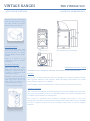
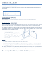
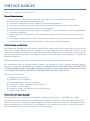
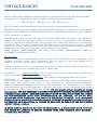
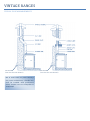
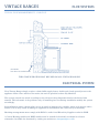
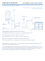
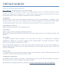
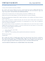
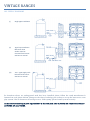
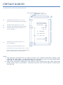
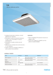
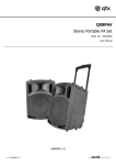
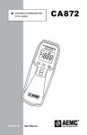
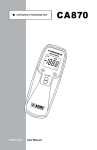
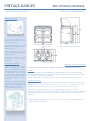
VINTAGE RANGES THE VINTAGE ORIGINAL APPLIANCE DETAILS OVERALL DIMENSIONS Oven specifications All ovens are constructed from 5mm thick steel and are vented into the flue system. Right hand side ovens x2 are Length 575mm, Width 406mm, Height 355mm [1] Flue 125Ø Connection See Connecting your Vintage Left hand side oven x1 is Length 575mm, Width 406mm, Height 355mm Each has a choice of 3 rail positions to place the chrome steel racks. Hot Plates & Castings Laser cut from steel 20mm thick, the circular hot plates have been maximized giving a full 400mm Ø and are covered by beautifully hand crafted cast iron lids. Nestled tightly between the circular hot plates is an ‘Axe Head’ of similar proportion. Detailed to match the lids are four cast iron doors mounted on solid brass hinge blocks* and held closed by means of a spring loaded latch system. Axe head hot plate DIMENSIONS ARE NOT TO SCALE ELECTRICAL AND PLUMBING DETAILS ARE AT THE END OF THIS SECTION. Finishes Doors, lids, top plate and front plate are finished in a Vitreous enamel coating. The top plate enamel is acid resistant. Trims including control knobs are of solid brass, Chrome options are available. NB. Available vitreous enamel colours can be found on a separate data sheet. Appliance Controls The upper right hand side oven has two stainless steel thermostats located in the middle left of the oven, one is for oven control; the other is a high limit safety stat which is manually reset by means of a push button on the control panel. The ovens are extremely heat retentive, requiring the burner to fire very infrequently, therefore, excellent fuel economy can be easily achieved, but enabling the user to prepare a meal for one or a banquet with no loss of oven or hotplate function. [1] Depending on model this is either an oven or position of central heating boiler. * Chrome Option Available. VINTAGE RANGES THE VINTAGE 1500 APPLIANCE DETAILS OVERALL DIMENSIONS Oven specifications [1] All ovens are constructed from 5mm thick steel and are vented into the flue system. Right hand side ovens x2, Left hand side ovens x2 and central oven x 1 are Length 575mm, Width 406mm, Height 355mm # GRIDDLE HOT PLATE FLUE 125Ø CONNECTION See Connecting your Vintage 1 1 Each has a choice of 3 rail positions to place the chrome steel racks. Hot Plates & Castings Laser cut from steel 20mm thick, the circular hot plates have been maximized giving a full 400mm Ø and are covered by beautifully hand crafted cast iron lids. Nestled tightly between the circular hot plates is an ‘Axe Head’ of similar proportion. The griddle hot plate # completes the staggering amount of cooking surface and is 400Ø x 465mm long. Detailed to match the lids are six cast iron doors mounted on solid brass hinge blocks* and held closed by means of a spring loaded latch system. CHOKE 1 AXE HEAD HOT PLATE DIMENSIONS ARE NOT TO SCALE ELECTRICAL AND PLUMBING DETAILS ARE AT THE END OF THIS SECTION. Finishes Doors, lids, top plate and front plate are finished in a Vitreous enamel coating. The top plate enamel is acid resistant. Trims including control knobs are of solid brass, though options are available (please ask for details). NB. Available vitreous enamel colours can be found on a separate data sheet. Appliance Controls The upper right hand side oven has two stainless steel thermostats located in the middle left of the oven, one is for oven control; the other is a high limit safety stat which is manually reset by means of a push button on the control panel. The ovens are extremely heat retentive, requiring the burner to fire very infrequently, therefore, excellent fuel economy can be easily achieved, but enabling the user to prepare a meal for one or a banquet with no loss of oven or hotplate function. [1] Depending on model this is either an oven or position of central heating boiler. * Chrome Option Available. # Griddle Slab may be replaced with an electric hob or gas hob – at extra cost. VINTAGE RANGES THE VINTAGE 840 APPLIANCE DETAILS OVERALL DIMENSIONS Oven specifications [1] All ovens are constructed from 5mm thick steel and are vented into the flue system. Flue 100Ø Connection Right hand side ovens x2 are Length 575mm, Width 406mm, Height 355mm See Connecting your Vintage Left hand side oven x1 is Length 575mm, Width 246mm, Height 355mm Each has a choice of 3 rail positions to place the chrome steel racks. Axe Head Hot Plate Hot Plates & Castings DIMENSIONS ARE NOT TO SCALE Laser cut from steel 20mm thick, the circular hot plates have been maximized giving a full 360mm Ø and are covered by beautifully hand crafted cast iron lids. Nestled tightly between the circular hot plates is an ‘Axe Head’ of similar proportion. ELECTRICAL AND PLUMBING DETAILS ARE AT THE END OF THIS SECTION. Detailed to match the lids are four cast iron doors mounted on solid brass hinge blocks* and held closed by means of a spring loaded latch system. Appliance Controls Finishes Doors, lids, top plate and front plate are finished in a Vitreous enamel coating. The top plate enamel is acid resistant. Trims including control knobs are of solid brass, Chrome options are available. NB. Available vitreous enamel colours can be found on a separate data sheet. The upper right hand side oven has two stainless steel thermostats located in the middle left of the oven, one is for oven control; the other is a high limit safety stat which is manually reset by means of a push button on the control panel. The ovens are extremely heat retentive, requiring the burner to fire very infrequently, therefore, excellent fuel economy can be easily achieved, but enabling the user to prepare a meal for one or a banquet with no loss of oven or hotplate function. FOR HOT WATER AND CENTRAL HEATING OPTIONS REFER TO THE BOILER SECTION OF THIS MANUAL. * Chrome Option Available. VINTAGE RANGES THE VINTAGE 500 APPLIANCE DETAILS OVERALL DIMENSIONS Size has not been compromised with this little beauty as with all other models the Vintage 500 has huge oven capacity. Oven specifications Flue 100Ø Connection Constructed from 5mm thick steel and vented into the flue system O/A sizes are Length 575mm, Width 406mm, Height 355mm See Connecting your Vintage There is a choice of 3 rail positions to place the chrome steel racks. Hot Plate & Castings Laser cut from steel 20mm thick, the circular hot plate is a staggering 400mm Ø and is covered by a beautifully hand crafted cast iron lid. ELECTRICAL AND PLUMBING DETAILS ARE AT THE END OF THIS SECTION. Detailed to match the lids are two cast iron doors mounted on solid brass hinge blocks* and held closed by means of a spring loaded latch system. Doors, lids, top plate and front plate are finished in a Vitreous enamel coating. The top plate enamel is acid resistant. Trims including control knobs are of solid brass, Chrome options are available. * Chrome Option Available DIMENSIONS ARE NOT TO SCALE Finishes NB. Available vitreous enamel colours can be found on a separate data sheet. Appliance Controls The oven has two stainless steel thermostats located in the middle left of the oven, one is for oven control; the other is a high limit safety stat which is manually reset by means of push button on control panel. The ovens are extremely heat retentive, requiring the burner to fire very infrequently, therefore, excellent fuel economy can be easily achieved, but enabling the user to prepare a meal for one or a banquet with no loss of oven or hotplate function. VINTAGE RANGES DELIVERY AND TRANSPORTATION Your Vintage Range is a robust, solid and heavy appliance. When attempting to move/transport please plan properly. MODEL Vintage 500 Vintage 840 Vintage Original Vintage 1500 WEIGHT (approx) Kg 300 480 590 950 TRANSPORTATION – IN VEHICLE Ensure appliance is securely held by straps and handled carefully by competent personnel. TRANSPORTATION – IN PROPERTY Remove all breakables, rugs and other obstructions from your path – If a doorway is too narrow, unhinge door, it will make entry easier, avoiding damage to appliance, property and most importantly persons. The plinth on the appliance is flat based and strong enough to permit the unit to be moved on rollers. If your appliance has been delivered with doors fitted, they may be removed from the unit to provide better handholds and reduce the weight of cooker. Door Removal Method Loosen Hex Block grub screws (a) 2 off. Remove door away from front plate in the direction of arrow. Note: Always place doors on a protective surface in the sequence they were removed. (a) (a) DO NOT Lift the appliance by the top plate or move it by the top plate. Use objects to lever or move the appliance, which may result in damage to it, property or persons. Risk moving appliance over difficult terrain, down steps or up steps without adequate manpower and proper precautions. NB: We can, with sufficient notice provide an authorised engineer to attend site, strip down the appliance and rebuild in situ. The charge for this specialist service is dependant on conditions and travel distances involved. Please do not strip and rebuild the cooker yourself. This will invalidate your warranty. VINTAGE RANGES SITE AND SYSTEM CONSIDERATION General Considerations 1) 2) 3) 4) 5) 6) Adequate space for appliance, especially access for service and maintenance purposes Provision of a satisfactory flue/chimney/cowl. A solid non-combustible hearth capable of supporting the appliance. Access to an outside wall or some other means of supplying unrestricted air to the burner. Non-combustible walls/surfaces adjacent to the appliance. If positioned within an inglenook, allow a minimum of 1.7 meters height clearance for comfortable operation of appliance. 7) Allow 25mm clearance to kitchen units and 10mm clearance to worktops, allow for connection of services. 8) The appliance must NOT be built in. The top plate and front plate especially must be removable for maintenance. Do not tile onto top plate or trap top plate between worktops. Heating system consideration The design and installation of the heating system must comply with all the regulations and statutes in force. Your Vintage Range should be installed in a fully pumped system complying with the design requirements of Honeywell S-Plan or equivalent. Should the installation be into an open vented system it will function efficiently provided the original system has been appraised and modified by a competent installation engineer. Reference should be made to the schematic illustration found in ‘Installation Information’ For installations into an existing heating system it is essential to have a qualified heating engineer survey the system for compatibility and suitability. PLEASE DO NOT ASSUME THAT BECAUSE THE SYSTEM WORKED WITH ANOTHER APPLIANCE THAT IT WILL WORK WITH A NEW APPLIANCE – SYSTEMS MUST MEET THE DESIGN CRITERIA FOR THE NEW APPLIANCE. This survey must include:1) 2) 3) 4) 5) 6) 7) Design & type of system Radiator size and condition Pipe work/fittings – size and condition Ancillaries – pump, expansion vessel, tanks etc. Cylinder – size & condition Insulation quality and characteristics of the property Safety of installation Heat to the room (space heating) The Vintage Range is extremely well insulated, radiating between 3,000 – 7,000 BTU’s (1 – 2kw) dependant on model, and mode of use. This makes it ideal for summer use where the kitchen space is to be maintained cool. For additional space heating one can lift the lid domes, this has no detrimental affect on oven temperatures. In winter use we recommend use of a suitably sized radiator, to heat the room in which the appliance is situated, particularly in larger kitchens. VINTAGE RANGES FLUE SYSTEMS Correct and proper installation of the flue system is essential for the safe, efficient and proper running of your Vintage Range. Please comply with all relevant regulations: BS 5410 : pt 1 - BS 6461 : pt 2 - BS 7566 pts 1 - 4 DO NOT install your Vintage Range into a flue system serving another appliance. DO NOT install your Vintage Range into a flue which is known to be problematic or may not be suitable for this application. Seek professional advice. A flue draught of between 0.04” and 0.08” WG is required on a cold flue. DO NOT construct a flue of single skin pipe for external installation: this will result in condensation (use suitable twin walled insulated pipe systems). In certain cases, due to geographical and/or barometric factors, an external twin walled flue may cause nuisance oven condensation when the oven is rising from temperature below dew point; if possible, flue internally or use the fan flue option. Whenever a flexible liner is used, it must be of 125mm diameter or (the same diameter as your Vintage flue outlet spigot). All flue systems must comply with regulations and be certified by your installer. HEAT ENGINE DEVELOPMENTS LTD WILL NOT ACCEPT RESPONSIBILITY FOR AN INCORRECTLY INSTALLED FLUE. Flue terminals Pressure jet appliances operate under positive pressure. Due to particular weather conditions, down draughts or excessive suction can be experienced. The flue requires an anti down draught cowl to stabilize it and also to prevent ingress of water or draught. If using salt glazed clay liners, it is imperative the liners are properly jointed, sealed and flaunched. In some cases clay liners are unsuitable and require a flexible liner. Flue height – Domestic Dwellings - No less than 4 meters (15 feet). The terminal should extend above the roof /ridge as laid down in OFTEC regulations. Mobile Homes and Boats - The terminal should extend 300mm above roof line. FAN FLUES In cases where the only option is low-level discharge, a fan flue must be fitted. However, the application must satisfy your installer with regard to wind conditions and adjacent features/obstructions. HEAT ENGINE DEVELOPMENTS LTD will not accept responsibility for an appliance or fan assembly subject to damage due to wind backpressure or incorrect installation. Vertical and horizontal fan options are available. At all times be advised by your installer NB wind pressure or down draughts can damage your appliance. THE FAN ASSEMBLY IS CONSTANT RUNNING TO ENSURE THE FLUE SYSTEM IS DYNAMIC AT ALL TIMES – THIS ENSURES FIRE UP EVEN ON VERY COLD START UPS. UNDER NO CIRCUMSTANCES MUST THIS CONFIGURATION BE ALTERED, TO DO SO WILL INVALIDATE YOUR WARRANTY. SEE FAN FLUE TECHNICAL BULLETIN. IT IS IMPORTANT WHEN FITTING A FAN FLUE TO ENSURE THE AIR INTAKE(S) IS AS REMOTE FROM THE POINT OF EXHAUST AS IS PRACTICAL, i.e. EITHER TO THE LEFT OR RIGHT OF THE FAN CENTRE LINE BY 1500mm – 2000mm. IN SOME CASES A FAN FLUE MAY NOT BE NECESSARY, i.e. A VERY SHORT FLUE PIPE RUN, NOT PRONE TO AFFECTS OF STRONG GUSTING WIND (FOR COOKING ONLY MODELS) – PLEASE CALL FOR ADVISE. VINTAGE RANGES TYPICAL FLUE ARRANGEMENTS Air intake (one duct for each burner) NB: In some cases clay lined chimneys may cause condensation, a flexible liner must be installed. Seek professional advice. Pumice liners are acceptable of 125Ø/150Ø Air intake (one duct for each burner) VINTAGE RANGES FLUE SYSTEMS TYPICAL FLUE ARRANGEMENTS - FAN FLUE Air intake (one duct for each burner) THIS CONFIGURATION MAY BE USED ON ALL VINTAGE RANGES ELECTRICAL SYSTEM Your Vintage Range simply requires a 240v 50Hz supply from a double pole fused spur adjacent to the appliance outlet. Once wired to the mains, the unit is operable.(cooker only Models)* The system controls are wired according to the relevant wiring diagrams found at the back of this manual. This schematic is for guidance only; if installing into an existing installation modify the system accordingly. In installations where voltage spikes occur or supply is known to be variable, please seek proper advice, failure to do so may result in damage to appliance or installation and could void your warranty. Earthing arrangements must comply with BS7671 and/or local Electricity Suppliers rules for PME. * Central Heating models and DHW models must be installed electrically as shown in relevant schematics (available for download by visiting our website at vintageranges.co.uk). VINTAGE RANGES PLUMBING AND ELECTRICAL HEATING SYSTEM SCHEMATIC LAYOUT Typical Mains Pressure Indirect Cylinder, Plumbed And wired Honeywell S-Plan THIS SCHEMATIC SKETCH IS FOR GUIDANCE ONLY All installation works must be carried out by a qualified engineer. Good plumbing practice must be followed at all times. This schematic is not to scale – positions shown are not accurate. Pipe sizes are important for satisfactory performance and safety. Cylinder and expansion vessel capacity must be adequate for system / property. Heating system circulatory pump – the pump must be capable of displacing the heating circuit water for the given output of the boiler. Your Vintage Range must be compatible with the output required by the heating system. Account must be taken of domestic hot water requirement, radiator sizes, location & pipe losses. This value must not exceed 95% of the boiler output capacity when calculated at an outside temperature of -1°c and a minimum radiator demand of not less than 50% of the boiler output capacity. VINTAGE RANGES HEATING SYSTEM REQUIREMENTS System Design – Requirements for your Vintage Range All Vintage Ranges are designed to operate on a fully pumped system. It is preferred that the system should be pressurised (in the range of 0.2 – 1.0 bar). If the system is old and is assessed that it can not be pressurised, please ensure condition of expansion system is satisfactory. CONTROLS The Honeywell ‘S’ plan system will allow for satisfactory control of the installation, controlling central heating, domestic hot water and cooking from the integral programmer and internal control panel, external programmable room stat or under floor heating manifold. Please seek professional advice. THE HEATING CIRCUIT Must incorporate a by-pass valve (automatic type) PIPE SIZING Primary pipes must be a minimum of 28mm diameter. The system must be fitted with drain off cocks at the lowest points and are to be readily accessible. See BS2879 CYLINDER A suitably insulated indirect cylinder of not less than 160 litres is recommended for optimum performance. Ideally use a 210 litre cylinder for the average family. For larger properties or larger families we recommend a 300/400 litre cylinder. The system should incorporate a 3 bar safety valve fitted to the flow pipe as close to the appliance as possible. Make certain that if the valve should discharge it will not cause personal injury or affect the electrical installation. FROST STAT It is advisable to fit a frost stat if the locality is subject to severe frosts or if the dwelling is going to be left unused for a period of time during the winter months. CORROSION INHIBITOR An inhibitor must be added to the water system after the entire system has been flushed. If system is later drained for any reason, inhibitor must again be added. Please follow these H S R instructions carefully or YOUR GUARANTEE MAY BE INVALIDATED. VINTAGE RANGES OIL/GAS SUPPLY OIL SUPPLY AND INSTALLATION A storage tank installation should meet BS5420. For a plastic tank, install to BS799 Pt1 and for a tank of mild steel install to OFTEC STD OFS T100. Ensure the tank is properly supported and maintained. Supply line from tank should be copper and copper fittings ONLY - DO NOT USE GALVANISED MATERIALS. All joints must be tight and only oil resisting jointing compounds and PTFE tape used. Piping must be protected from damage even when under ground, use plastic sheathing. The size and configuration of piping will be largely dependant on site conditions and distances between tank and appliance. Prior to entry into property a suitable fuel safety shut off valve must be fitted and the sensor must be securely fixed in the burner chamber with clips. It is recommended to use a 65°c valve in combination with a valve adjacent to appliance. We recommend that oil tanks are positioned at least 300mm above the level of the burner. IN ALL CASES where the head of oil is negative i.e. oil level is below the level of the burner or in cases where there may be another appliance on the same line. It is essential to install either:i. ii. iii. A non-return valve in the oil line A 2 pipe system A tiger loop – when installing, follow regulations & manufacturers instructions NB: See burner manual GAS SUPPLY For a cooker only model a 15mmØ copper supply line with external shut off valve is sufficient. For central heating models use 22/28mmØ copper supply line with external shut off valve. In cases where the incoming supply is a distance from where you’re Vintage is to be sited, please size up the supply pipe work to minimise pressure drop to unit (20mb NG/38mb LPG). ALWAYS EMPLOY SERVICES OF A REGISTERED CORGI ENGINEER. VINTAGE RANGES OIL SUPPLY DIAGRAMS (i) Single pipe installation (ii) Tiger loop installation NB: Horse-shoe washer must be removed from burner. See burner manual (iii) Two – pipe supply tank below level of burner. See burner manual In situations where an underground tank has been installed please follow the tank manufacturer’s instructions, and please inform Vintage at the time of ordering your cooker to set up the burners as a two pipe system. Also in instances of having to use a ‘Lifter pump’ please install system correctly. ALWAYS USE BEST QUALITY EQUIPMENT & MATERIALS AND ALWAYS BE PROFESSIONALLY ADVISED AT ALL TIMES. VINTAGE RANGES CONNECTING YOUR VINTAGE RANGE FLUE SPIGOT (FOR 500,840 – 100Ø) (ORIGINAL, 1500 – 125) ID T4 CH/DHW OUTLET VINTAGE 500, 840 AND ORIGINAL DHW MODELS (SINGLE BURNER) T4 T3 CH/DHW INLET VINTAGE 500, 840 AND ORIGINAL DHW MODELS (SINGLE BURNER) T3 T2 CH/DHW OUTLET VINTAGE ORIGINAL, 840 AND 1500 MODELS T2 AIR SUPPLY TUBE 500 AND VARIOUS COOKER ONLY MODELS E KB O/G E – ELECTRIC KB – KBB VALVE O/G - OIL - GAS AIR SUPPLY TUBES T1 CH/DHW INLET VINTAGE ORIGINAL, 840 AND 1500 MODELS T1 T1/T2/T3/T4 ARE 28mmØ SOCKETS (1”BSP) T1/T2 ABOVE 100,000 BTU’S ARE 35mmØ (1 1/4” BSP) ALWAYS USE GOOD QUALITY BRASS COMPRESSION FITTINGS WHEN MAKING A CONNECTION NOTE: 1) THE BOILER CONNECTIONS ON THE VINTAGE 1500 CENTRAL HEATING MODEL ARE ALWAYS TO THE REAR – SAME HEIGHTS AS T1/T2 ABOVE AND AT THE SAME REAR CENTRES AS THE ORIGINAL CENTRAL HEATING MODEL. 2) THE FUEL, ELECTRIC SERVICES, AIR SUPPLY AND WATER MAY BE LEFT HAND OR RIGHT HAND FOR A 500 MODEL – PLEASE ALWAYS CALL OUR TECHNICAL HELPLINE TO DISCUSS. VINTAGE RANGES USING YOUR VINTAGE RANGE Your Vintage Range has been commissioned, and is now ready for use. On opening the control door you will see the control panel. During heating of oven from cold lift the left hand lid to reduce the maximum temperature of the hot plate, leave lid in the upright position until oven control stat regulates the burner. At all other times the lids can be left in any position. Start up procedure 1) Switch the Green oven on/off switch to I (on). Switch will illuminate 2) Move programmer sliders to Cont.(top slider) 3) Turn the Oven control to 175° and the Boiler control (if applicable) to Position 4. The burner will fire. You now have control of your Vintage hot plates and ovens. To manually shut down your Vintage in cooker mode, please use the following procedure. Shut down procedure 1) Position cooker programmer slider to the OFF position. 2) Set the control knob to OFF. We recommend you acquaint yourself with the basic controls of your Vintage appliance before you start using the in-built programmer. Summer use In exceptionally hot weather you may operate your Vintage on timer – leave the lids down when the hot plates are not required. Winter use During the winter, early spring and late autumn you may operate your Vintage on continuous mode at a low tick over temperature of 50/80°C, dialling up higher temperatures for cooking – the lids may be left up to provide additional space heating*. Range cooking is different, it is a very simple and practical way of preparing food – for some informative information visit our website vintageranges.co.uk, click on ‘Extras’ and follow the link to download our Practical Cooking Guide. When programming your Vintage to come on during hot weather, please do not allow foods to remain at temperatures that could result in bacterial contamination. Always defrost food thoroughly prior to cooking. It is not our wish to begin to instruct the customer on how to cook. Should you require advice on cooking or recipes best suited to range cooking, your dealer should be more than happy to help. DO NOT operate your range cooker with the top right hand door #open – this bypasses the controls and will cause damage to your appliance. The left hand lid should be left in the upright position for 30 minutes when starting from cold. * if you intend to leave the cooker on whilst you are not resident (for periods of 10 days or more), please leave the ovens set at 80+ to avoid the likelihood of condensation collecting in the internal flue ways of the cooker – particularly gas models. # Control Oven. VINTAGE RANGES LOOKING AFTER YOUR VINTAGE Your Vintage range is finished in a lustrous vitreous enamel. Enamel is a very robust finish, but care must be taken to protect it. a) Hard/Heavy objects might chip or scratch the enamel surface of the top plate. b) Avoid striking the enamel with hard objects. c) Daily wipe the range surfaces with a soapy damp cloth and polish with a duster. Do not do this if the appliance is hot. d) Always wipe off spillages as they happen using a moist cloth. The top plate is acid resistant, however always wipe off fruit juices, milk etc., especially if cooker is warm. Do not put a wet cloth on hot enamel. e) Use an approved cream cleanser when required – look for the VEDC mark. f) Never use abrasive cleaners or scouring pads on enamel. g) Food stuffs containing sugars can damage enamel – wipe off immediately. h) Deep frying pans must never be used on your Vintage. Should the hot oil boil over it would seep into the insulation presenting a fire hazard. Care of hot plates and ovens Hot plates may be cleaned using a suede brush and sealed with vegetable oil or olive oil. Do not use too much oil this could seep into the insulation presenting a fire hazard. Turning the ovens up to max temperature will cause deposits to carburise. Once cool only use oven cleaning implements to remove deposits. After cleaning, oil the ovens using vegetable oil or olive oil to seal them.