1
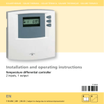
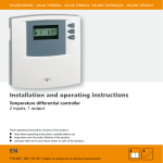
SOLARTHERMIE - SOLAR THERMAL - SOLAR TÉRMICO - SOLAIRE THERMIQUE Operating instructions Temperature differential controller 3 inputs, 1 output These operating instructions are part of the product. Read these operating instructions carefully before use, keep them over the entire lifetime of the product, and pass them on to any future owner or user of this product. EN 709.752 | Z02 | 07.50 | Subject to change due to technical improvements! EN Contents 1 1.1 1.2 1.3 About this manual ....................... 3 Applicability .....................................3 Users.................................................3 Description of symbols ....................4 2 2.1 2.2 2.3 Safety ............................................ 5 Proper usage ....................................5 Improper usage................................5 Dangers during installation and commissioning.................................6 2.4 Detecting faults................................7 2.5 Exclusion of liability..........................7 3 Description ................................... 9 3.1 Controller in the solar circuit ...........9 3.2 Casing overview .............................11 4 4.1 4.2 4.3 Installation .................................. 12 Opening/closing the casing ...........12 Mounting .......................................13 Electrical connection .....................14 5 Display overview ........................ 18 2 6 Commissioning .......................... 19 7 Description of controller functions..................................... 20 Automatic storage tank charging..20 Maximum storage tank temperature ...................................21 Maximum collector temperature...21 Tube collector function ..................21 Holiday function ............................22 Anti-freeze function .......................23 7.1 7.2 7.3 7.4 7.5 7.6 8 Operation.................................... 24 8.1 Reading temperature values..........24 8.2 Setting the controller .....................24 9 Maintenance............................... 29 9.1 Fault causes ....................................29 9.2 Testing the temperature sensors....33 10 Dismantling and disposal .......... 35 11 Legal guarantee ........................ 36 12 Technical data ............................. 37 709.752 | 07.50 EN 1 About this manual 1.1 Applicability This manual describes the installation, commissioning, operation, maintenance and dismantling of the temperature differential controller for solar thermal energy systems. When installing the remaining components, e.g. solar collectors, pump assemblies, storage units, pumps and switching valves, be sure to observe the appropriate installation instructions provided by each manufacturer. 1.2 Users Installation, commissioning, maintenance and dismantling of the controller may only be performed by trained professional personnel. Before commissioning, the controller must be professionally assembled and installed by professional personnel in accordance with the applicable regional and transregional regulations as well as the safety instructions and general instructions within these installation and operating instructions. The professional personnel must be familiar with these operating instructions. The controller is maintenance-free. Use the controller only after first thoroughly reading and understanding this instruction manual and the safety instructions. Adhere to all safety instructions. In the event of any ambiguities regarding the operation 709.752 | 07.50 3 EN and alteration of parameters or functions, consult professional personnel. 1.3 Description of symbols 1.3.1 The structure of the warning notices SIGNAL WORD Type, source and consequences of the danger! Measures for avoiding danger. 1.3.2 Danger levels in warning notices Danger level Likelihoodof occurrence DANGER Consequences resulting from noncompliance Imminent threat Death, serious bodily of danger injury Possible threat of WARNING danger Possible threat of CAUTION danger CAUTION Possible threat of danger Death, serious bodily injury Minor bodily injury Property damage 1.3.3 Notes NOTE Note on easier and safer working habits. 4 Measures for easier and safer working habits. 709.752 | 07.50 EN 1.3.4 Other symbols and markings Symbol Meaning Call to action Result of action • List Emphasis on issue at hand Emphasis on issue at hand Precondition for action 2 Safety 2.1 Proper usage The temperature differential controller (called controller in the following) may only be used for controlling solar thermal systems within the permissible ambient conditions (see chapter 12). 2.2 Improper usage The controller must not be operated in the following environments: • outdoors • in damp rooms • in rooms where highly flammable gas mixtures can occur • in rooms in which the operation of electrical and electronic components may cause dangers to arise 709.752 | 07.50 5 EN 2.3 Dangers during installation and commissioning The following dangers exist during installation / commissioning of the controller and during operation (in case of installation errors): • Risk of death by electrocution • Risk of fire due to short-circuit • Damage to any of the constructional fire safety measures present in the building due to incorrectly installed cables • Damage to the controller and connected devices due to improper ambient conditions, inappropriate power supply and connecting prohibited devices or faulty devices and incorrect assembly or installation Therefore, all safety regulations apply when working on the mains supply. Only electricians may perform work that requires opening the controller (such as electrical connection work). 6 When laying cables, ensure that no damage occurs to any of the constructional fire safety measures present in the building. Make sure that the permissible ambient conditions at the installation site are not exceeded (see chapter 12). Be sure to comply with the specified protection degree. Factory labels and markings may not be altered, removed or rendered unreadable. 709.752 | 07.50 EN Before connecting the device, make sure that the power supply matches the specifications on the type plate. Make sure that all devices which are connected to the controller conform to the technical data of the controller. Secure the device against unintentional start-up. All work on an open controller must be performed with the mains supply disconnected. Protect the controller against overloading and short-circuiting. 2.4 Detecting faults Check the display regularly. In case of faults, isolate the cause (see chapter 9). As soon as it becomes evident that safe operation is no longer possible (e.g. visible damage), remove the device from the mains supply immediately. Have professional personnel remedy the fault. 2.5 Exclusion of liability The manufacturer cannot monitor the compliance with this manual or the conditions and methods during the installation, operation, usage and maintenance of the controller. Improper installation of the system may result in damage to property and, as a result, to bodily injury. Therefore, we assume no responsibility and liability 709.752 | 07.50 7 EN for loss, damage or costs which result from or are in any way related to incorrect installation, incorrect execution of installation work, improper operation and incorrect usage and maintenance. Similarly, we assume no responsibility for patent right or other right infringements of third parties caused by usage of this controller. The manufacturer reserves the right to make changes to the product, technical data or installation and operating instructions without prior notice. 8 709.752 | 07.50 EN 3 Description 3.1 Controller in the solar circuit 3.1.1 The purpose of the controller The controller controls the solar thermal system 3.1.2 The structure of the solar circuit Temperature sensor 1 (collector sensor) Temperature differential controller T1 Temperature sensor 3 (upper area of storage tank) Storage tank Collector T3 Solar circuit Pump T2 709.752 | 07.50 Temperature sensor 2 (lower area of storage tank) 9 EN 3.1.3 The function of the solar circuit The controller constantly compares the temperatures between the collector (T1) and the lower area of the storage tank (T2). Once the sun heats the collector and there is a temperature difference of 8 K between the collector and the storage tank, the pump is switched on. The pump extracts the heat transfer fluid from the lower cooler area of the storage tank and pumps it to the collector. The heat transfer fluid in the collector is heated by the sun and flows back to the storage tank. The heat transfer fluid heats the domestic water via a heat exchanger located in the storage tank. 10 709.752 | 07.50 EN 3.2 Casing overview Display graphic display, animated, for controller operation and system settings Operating switch The following modes of operation can be selected:On for commissioning and testing for functionAutomatic for automatic operation Operating buttons Arrow up SET button Arrow down - Off to switch-off the pumps On Connections Automatic Pump, mains grid, temperature sensor Off 709.752 | 07.50 11 EN 4 Installation 4.1 Opening/closing the casing DANGER Risk of death by electrocution! Remove the controller from the power supply before opening the casing. Make sure that the power supply cannot be unintentionally switched on. Do not damage the casing. Only switch the power supply back on after the casing has been closed. Latches The upper casing is connected to the lower casing by two latches, and fastened with a screw. Operating buttons 4.1.1 Opening the casing Loosen the screw and remove the upper casing in an upwards direction. 4.1.2 Closing the casing 12 Place the upper casing over the lower casing at an angle. Insert the latches into the recesses of the lower casing. Pivot the upper casing down and feed the operating buttons through the matching holes. Fasten the casing tightly with the screw. 709.752 | 07.50 Screw Upper casing Lower casing EN 4.2 Mounting WARNING Risk of electrical shock and fire if mounted in a damp environment! Only assemble the controller in an area where the degree of protection is sufficient. 4.2.1 Mounting the controller CAUTION Risk of injury and damage to the casing when drilling! 1 Do not use the casing as a drilling template. Choose a suitable installation site. Drill the upper fastening hole. Screw in the screw. Remove the upper casing. Hang the casing in recess . Mark the position of the lower fastening holes ,. Remove the casing again. Drill the lower fastening holes. Hang the casing in recess . Screw the casing firmly using the lower fastening holes and . Mount the upper casing. 105 2 3 137,2 116 134 709.752 | 07.50 13 EN 4.3 Electrical connection WARNING Risk of death by electrocution! Remove the controller from the power supply before opening the casing. Observe all guidelines and regulations of the local electricity supplier. NOTE The device is to be connected to the grid by means of a plug with grounding contact, or in the case of a fixed electrical installation via a disconnection device for complete disconnection in accordance with the installation guidelines 4.3.1 Preparing the cable feed Depending on the type of installation, the cables may enter the device through the rear of the casing or the lower side of the casing. 14 709.752 | 07.50 EN Feeding the cable through the rear of the casing (diagram 1): WARNING Risk of electrical shock and fire due to cables coming loose! SET 7 Diagram 1: Cable feed from the rear Install an external strain relief for the cables. Remove the plastic flaps from the rear side of the casing using an appropriate tool. Feeding the cable through the lower side of the casing (diagram 2): WARNING SET Risk of electrical shock and fire due to cables coming loose! 6 Fasten the flexible cabling to the casing using the strain-relief clamps provided. Cut the left and right plastic flaps using an appropriate tool and break them out of the casing. 4.3.2 Connecting the cables Diagram 2: Cable feed from below If a protective conductor is provided or required for the pump, connect it to the controller terminals. When connecting the protective conductor, observe the following points: 709.752 | 07.50 15 EN Make sure that the grounding contact is also connected to the controller's mains supply side. - Each terminal may only be connected to a single connecting wire (max 2.5 mm2). - The terminals are suitable for connection without sleeves; stranded wires are to be twisted (1 twist per 20 mm). Only use the original temperature sensors (Pt1000) that are approved for use with the controller. Observe the following points: - The polarity of the sensor contacts is not important. - Do not lay sensor cables close to 230 volt or 400 volt cables (minimum separation: 100 mm. - If inductive effects are expected, e.g. from heavy current cables, overhead train cables, transformer substations, radio and television devices, amateur radio stations, microwave devices, etc. then the sensor cables must be adequately shielded. - Sensor cables may be extended to a maximum length of 100 m. When using extension cables, select the following cable cross sections: - 0.75 mm2 up to 50 m long - 1.5 mm2 up to 100 m long Connect the cables in accordance with the terminal plan. - 16 709.752 | 07.50 EN 4.3.3 Terminal plan N R1 N L1 N R1 N T1 T2 T3 P co rot nd ec uc tive (o to pt G r io rid na l 1 23 1 0 (o P 5 V V~ pt u ~ ) io mp na l 1 23 0 15 V V~ ~ ) Te m pe ra tu (lo re w T er em (c sen o Te a lle sor r p m ct 1 pe ea o era t (u ra f s ur or) e pp tu t o ra se er re ar sen ge nso ea so ta r 2 nk of r 3 ) st – or o ag pt e ion ta a nk l ) PE PE L 4.3.4 Actuating the connecting terminals NOTE The connecting terminal may only be actuated with an appropriate tool. An unsuitable tool or too much mechanical pressure can damage or even destroy the connecting terminal. 709.752 | 07.50 17 EN 5 Display overview 1 T1 12 T1 11 10 9 ! 888 max T3 °C max °F 3 D 7 6 4 5 1 Temperature sensor symbols 8 Solar circuit symbols 2 Display for temperature values and fault symbols, e.g. short circuit, interruption (see page 30) or SYS = system error (see page 39) 9 Displays message "Maximum storage tank temperature has been reached" 10 Warning display if faults occur, e.g. short circuit, interruption (see page 30) or SYS = system error (see page 31) 3 Holiday function (see pages 22/23) 4 Anti-freeze function (see page 23) 11 Displays message for evaporation of the collector fluid 5 Setting the temperature unit °C / °F 6 tube collector function 12 Displays message for "Sufficient heat supply" 7 Setting the maximum storage tank temperature 18 2 T1 T2 8 °E 709.752 | 07.50 EN 6 Commissioning 6.1 Testing the pump CAUTION Damage to pump caused by dry operation! Make sure that the solar circuit is filled with heat transfer fluid. The controller casing is closed All connections are properly made. The solar energy system is filled. °C T1 T1 ! T3 max T2 max °C °F D T1 °C T1 T1 ! T3 max T2 max °C °F T1 D Connect the mains supply. To switch on the pump, set the operating switch to the upper position (on). The display is backlit in red onappears in the display. After approx. 3 seconds on flashes in alternation with the display. To switch off the pump, set the operating switch to the lower position (oFF). The display is backlit in red oFFappears in the display. After approx. 3 seconds oFF flashes in alternation with the display. 709.752 | 07.50 19 EN CAUTION The incorrect operating mode may cause the system to shut down or impair proper functioning! After testing the pump, always set the operating switch to automatic operation. To set the controller to automatic operation, move the operating switch to the middle position (Auto). "Aut" is shown on the display for approx. 3 seconds. 7 Description of controller functions 7.1 Automatic storage tank charging The controller constantly compares the temperatures between the collector (T1) and the lower area of the storage tank (T2). As soon as the temperature in the collector (T1) is 8 K (constant fixed value) higher than the temperature in the storage tank (T2), the following display appears: • The sun symbol is displayed If no safety limits prohibit the pump from operating, the pump is switched on. The following display appears: • The pump symbol rotates 20 T1 ! T3 max T2 If the temperature difference falls below 4 K (constant fixed value), the pump is switched off. The sun symbol is no longer shown on the display. 709.752 | 07.50 40 T1 max °C °F T1 D °C EN 7.2 60 T1 T1 ! T3 max T2 °C • The sun symbol is displayed max °C °F • The max indication flashes in the storage tank symbol D T1 7.3 °C T1 T1 ! T3 max T2 °F T1 Maximum collector temperature During periods of high solar irradiance, the temperature (T1) of the heat transfer fluid can exceed 130°C. The heat transfer fluid evaporates. In this case, the pump is stopped for protection purposes until the temperature drops below 127°C. The following displays appear: • The pump symbol does not move max °C Maximum storage tank temperature • If the lower area of the storage tank (T2) reaches the set maximum storage tank temperature (factory setting 60 °C), charging is stopped. A temperature of 3 K below the maximum storage tank temperature must first be reached before charging can be resumed. The following displays appear:The pump symbol does not move D • The sun symbol is displayed • The vapour symbol flashes 7.4 Tube collector function For reasons of construction the collector temperature (T1) can only be imprecisely recorded with vacuum tube collectors (in many cases there are no immersion sensors; the sensor is outside the collector pipe). In 709.752 | 07.50 21 EN these cases, the solar circuit must be briefly activated at regular intervals to transmit the actual heat from the collector pipe to the sensor (T1). If the tube collector function is activated, the controller automatically switches the pump on every 30 minutes for 30 seconds. T1 The following display appears: T1 • The lower temperature sensor, T1, is shown. 7.5 Holiday function T3 max T2 The holiday function is used to cool down a completely heated storage tank again via the collector. The storage tank can heat up too much, e.g. if no hot water is extracted from the storage tank over an extended period of time (holiday) of intense solar irradiance. A completely heated storage tank subjects the solar energy system to a higher thermal load and the solar fluid can evaporate. If the holiday function is activated, the storage tank is cooled as follows: If the temperature in the storage tank rises to 10 K below the set storage tank maximum temperature, the controller attempts to discharge the lower section of the storage tank to 35°C (e.g. at night). To do so, the pump is automatically switched on once the collector is 8 K colder than the storage tank. Once the temperature difference between the collector and the storage tank is only 4 K, the pump is switched off again. 22 ! 709.752 | 07.50 °C max °C °F T1 D EN °C T1 ! T3 max T2 max °C °F The following display appears: • The holiday symbol is displayed T1 7.6 D Anti-freeze function If the anti-freeze function is activated, the controller switches the pump on as soon as the collector temperature T1 falls below +5 °C. The heat transfer fluid is then pumped through the collector in an attempt to prevented the system from freezing. If the collector reaches a temperature of +7 °C, the pump is switched off again. T1 CAUTION The solar energy system can freeze despite the activated anti-freeze function! During a power outage, the anti-freeze function does not operate. During long-term periods of frost (due to restricted water tank heat storage). If collectors are mounted in locations exposed to wind. °C T1 T1 ! T3 max T2 max °C °F T1 D It is recommended to generally use heat transfer fluid with anti-freeze for solar energy systems. Standard anti-freeze heat transfer fluids for solar energy systems also contain an additional corrosion inhibitor. The following display appears: • The anti-freeze symbol is displayed 709.752 | 07.50 23 EN 8 Operation CAUTION The incorrect operating mode may cause the system to shut down or impair proper functioning! Make sure that the operating switch is set to automatic operation. 8.1 Reading temperature values NOTE The temperature in the above storage tank is only displayed if the temperature sensor T3 (not included in delivery) is also connected. Use the buttons and to select temperature sensor (T1, T2, T3). The selected temperature sensor and the current temperature reading appear in the display. 8.2 Setting the controller 24 T1 ! 8.2.1 Menu operation To open the Settings menu, press the SET button for approx. 2 seconds. The current storage tank maximum temperature is displayed. Symbol for the T2 temperature sensor and max flash. To switch to the next setting, press the or button. 709.752 | 07.50 48 T1 T3 max T2 max °C °F T1 D °C EN To exit the Settings menu, press the button again until the menu is no longer displayed. 8.2.2 Setting the storage tank maximum temperature CAUTION Risk of scalding by excessive domestic water temperature! 60 T1 T1 ! T3 max T2 °C °F Set the storage tank max. temperature no higher than 60°C. Install a thermostatic mixer in the hot water pipe and set to max. 60°C. The menu is open max °C D T1 Press the SET button for approx. 2 seconds until the storage tank maximum temperature flashes. Change the storage tank maximum temperature using the or buttons. To save the value, press the SET button. 8.2.3 Selecting the temperature unit °C T1 T1 ! T3 max T2 max °C °F T1 The menu is open D Press the button again until °C / °F flashes. Press the SET button for approx. 2 seconds until the desired temperature unit – °C or °F – flashes. 709.752 | 07.50 25 EN 8.2.4 Activating the tube collector function NOTE Incorrectly setting the controller can compromise the efficiency of the solar energy system. Therefore, only activate the tube collector function if the construction of the collector does not allow its temperature to be recorded immediately and/or accurately (in some cases there are no immersion sensors; the sensor is outside the collector pipe). The menu is open T1 Press the button again until the symbol for T1 flashes. Press the SET button for approx. 2 seconds until the symbol for T1 switches from the upper to the lower position. 8.2.5 Activating/deactivating the holiday function NOTE Incorrectly setting the controller can compromise the efficiency of the solar energy system. Only activate the holiday function if you intend to be absent for an extended period. Deactivate it again upon your return. 26 709.752 | 07.50 T1 ! T3 max T2 0Co max °C °F T1 D °C EN T1 T1 ! T3 max T2 0Co °C The menu is open max °C °F T1 D Press the button until the holiday symbol flashes. Press the SET button for approx. 2 seconds until the small tick on the holiday symbol appears/goes out. 8.2.6 Activating/deactivating the anti-freeze function CAUTION The solar energy system can freeze despite the activated anti-freeze function! During a power outage, the anti-freeze function does not operate. During long-term periods of frost, the system can freeze despite the anti-freeze function. If frost is expected for a long period of time, only operate the system with anti-freeze. NOTE Incorrectly setting the controller can compromise the efficiency of the solar energy system. Only activate the anti-freeze function for solar energy systems that are not filled with anti-freeze. 709.752 | 07.50 27 EN The menu is open 28 T1 Press the button until the anti-freeze symbol flashes. Press the SET button for approx. 2 seconds until the small tick on the anti-freeze symbol appears/goes out. 709.752 | 07.50 T1 ! T3 max T2 0Co max °C °F T1 D °C EN 9 Maintenance The controller was conceived for years of continuous trouble-free operation. Nevertheless, faults may occur. Maintenance may only be performed by professional personnel. In most cases, however, the fault does not lie with the controller, but rather with the peripheral components. The following description covers the most common problems encountered with the controller. Only send in the controller, with a precise fault description, if none of the following faults are present. 9.1 Fault causes WARNING Risk of death by electrocution! Remove the controller from the power supply before opening the casing. Controller does not appear to function at all. Secondary symptoms Possible cause / remedy The controller dis- No power supply present play is blank. Have professional personnel check the fuse and the supply cable. 709.752 | 07.50 29 EN The pump, which is connected to the controller, is not running, although its switch-on conditions have been fulfilled. Secondary symptoms Possible cause / remedy The pump symbol The pump connecting cable rotates in the dis- is not connected, interrupted play. or the fuse in the controller is burned out. If necessary, have professional personnel replace the fuse. (Replacement fuse is located in the casing). • The pump sym- Operating switch is set to manbol does not ual rotate Set the operating switch to • The display is backlit in red automatic operation. • OFF flashes • The pump sym- No fault. bol does not The system has stopped because rotate maximum collector temperature • The display is or maximum storage tank tembacklit in yellow perature have been reached. • Evaporation symbol or max are flashing 30 709.752 | 07.50 EN °C T1 T1 ! T3 max T2 max °C °F D T1 Short-circuit symbol and warning display appear. Secondary symptoms Possible cause / remedy • The pump symbol does not rotate Temperature sensor or its supply cable short-circuited • Display background alternately flashes red and yellow Have professional personnel check the supply cables of the temperature sensors and that they are correctly connected to the controller. NOTE In case of a T3 short-circuit the pump does not stop. °C T1 T1 ! T3 max T2 max °C °F T1 D Interruption symbol and warning signal appear Secondary symptoms Possible cause / remedy • The pump symbol does not rotate Temperature sensor T1 or T2 or its supply cable is interrupted • Display background alternately flashes red and yellow Have professional personnel check the supply cables of the temperature sensors and that they are correctly connected to the controller. NOTE 709.752 | 07.50 31 EN If T3 is interrupted no message appears T1 SYS flashes in the controller display ! Possible cause / remedy SYS means there is a system error. This means that despite the pump running, a temperature difference exceeding 80 K between the collector and the storage tank was recorded. The following causes are possible: • The pump is faulty or not correctly connected • The isolating valve in the solar circuit is still closed • Air is in the solar circuit Since a standard circulation pump cannot eliminate air bubbles inside the piping system, the heat transfer medium circuit comes to a standstill. 32 °C T1 Have professional personnel check the solar energy system to prevent damage. Once the fault has been remedied, press any button to acknowledge the fault message. 709.752 | 07.50 T3 max T2 max °C °F T1 D EN 9.2 Testing the temperature sensors 9.2.1 Safety Only professional personnel may test the temperature sensors. 9.2.2 Testing the resistance values DANGER Risk of death by electrocution! Remove the controller from the power supply before opening the casing. The temperature is recorded by resistance sensors. These are PT1000 temperature sensors. Depending on the temperature, the resistance value also changes. A potentially defective sensor can be checked using an ohmmeter. Measuring resistance values Disconnect the relevant temperature sensor from the controller. Measure the resistance value. The typical resistance values, depending on the temperature, are listed in the following table. Please note that small deviations are permissible. 709.752 | 07.50 33 EN Temperature sensor resistance values Temperature [°C] -30 -20 -10 0 Resistance [Ω] 882 922 961 1000 1039 1078 Temperature [°C] 30 40 50 60 Resistance [Ω] 1117 1155 1194 1232 1271 1309 Temperature [°C] 90 Resistance [Ω] 1347 1385 1423 1461 1498 1536 Temperature [°C] 150 Resistance [Ω] 1573 1611 1648 1685 34 100 160 110 170 10 70 120 130 20 80 140 180 709.752 | 07.50 EN 10 Dismantling and disposal DANGER Risk of death by electrocution! Remove the controller from the power supply before dismantling it. To dismantle the controller, follow the assembly instructions in the reverse order. Dispose of the controller in accordance with the regional regulations. 709.752 | 07.50 35 EN 11 Legal guarantee In accordance with German statutory regulations, there is a 2-year legal guarantee on this product for the customer. The seller will remove all manufacturing and material faults that occur in the product during the guarantee period and affect the correct functioning of the product. Natural wear and tear does not constitute a malfunction. No legal guarantee can be offered if the fault can be attributed to third parties, unprofessional installation or commissioning, incorrect or negligent handling, improper transport, excessive loading, use of improper equipment, faulty construction work, unsuitable construction location or improper operation or use. Legal guarantee claims shall only be accepted if notification of the fault is provided immediately after it is discovered. Guarantee claims are to be directed to the seller. The seller must be informed before guarantee claims are processed. For processing a guarantee claim an exact fault description and the invoice / delivery note must be provided. The seller can choose to fulfil the legal guarantee either by repair or replacement. If the product can neither be repaired nor replaced, or if this does not occur within a suitable period in spite of the specification of an extension period in writing by the customer, the reduction in value caused by the fault shall be replaced, or, if this is 36 709.752 | 07.50 EN not sufficient taking the interests of the end customer into consideration, the contract is cancelled. Any further claims against the seller based on this guarantee obligation, in particular claims for damages due to lost profit, loss-of-use or indirect damages are excluded, unless liability is obligatory by law. 12 Technical data Temperature differential controller Operational voltage 230 V~ (± 15 %), 50 Hz [optional 115 V (± 15%), 60 Hz] Controller's own consumption ≤1W Inputs 3 temperature recording (Pt1000) Output 1 switched output, switching performance max. 800 W [230 V~] Display Animated LCD display, 2-colour background Protection degree IP 20/DIN 40050 Permitted ambient temperature 0 to +45 °C Mounting wall-mounted Weight 250 g Casing recyclable 3-piece plastic casing Dimensions L x W x H [mm] 137 x 134 x 38 Temperature sensors 2 x Pt1000 1.5 m silicone cable (measuring range up to +180 °C) 709.752 | 07.50 37 709752