1
1. INTRODUCTION
This operation instruction manual conforms to the requirements of the 98/37/EEC Machine Directives and subsequent
amendments.
In the light of this, special attention has been given to safety aspects and accident prevention in the work-place for each
stage in the machine's "life". Information which could be of particular assistance to the operator has been highlighted.
The "Operating instructions" are an integral part of the machine and should be consulted before, during and
after the start up of the machine and whenever else required. The content of these instructions should always
be carefully observed.
The observance of the above is the only way to achieve the two fundamental aims of this manual:
• Optimization of machine performance
• Prevent damage to the machine and injury to the operator
The index of the chapters and the index of the drawings, diagrams and tables is contained in chapter 3 and can be used
to help the location of specific information.
CAUTION : BEFORE INSTALLING THE MACHINE, READ THE OPERATING
INSTRUCTIONS CAREFULLY
2. INFORMATION ABOUT MAINTENANCE ASSISTANCE
2.1 GUARANTEE
• MIVA S.a.s. products are guaranteed against material and manufacturing defects for a period of 12 months from the
date of delivery or, if the machine is installed by MIVA employees, from the date of machine start up.
• The buyer is only entitled to the replacement of parts which are acknowledged as faulty: carriage and packing are at
the buyer's expense.In the event of the above, the following information should be supplied:
1. Date and number of purchasing document
2. Machine model
3. Serial number
4. Code of any relevant drawings
• Requests for compensation for the inactivity of the machine will not be accepted.
• The guarantee does not cover uses which are not in line with these operating instructions which are an integral part
of the machine. Nor is maintenance covered if the instructions supplied are not observed.
• The guarantee will not cover machines which have undergone unauthorized modifications.
Modification or tampering with the safety devices is strictly forbidde
3. INDEX
3.1 INDEX OF CHAPTERS
Chap. 1
Introduction
Chap. 2
Information about maintenance assistance
Chap. 3
Index of chapters, drawings, diagrams and tables
Chap. 4
Description of the machine
Safety standards complied with during the design and construction of the machine
Description of the machine and its components
Chap. 5
Main technical data
Chap. 6
Installation
Chap. 7
Start up and operation
Devices and their location
Tools supplied
Operation
Special safety checks
General safety rules
Measures to prevent residual risks
Chap. 8
Maintenance and repairs
General safety measures
Routine checks and maintenance
Description of routine maintenance
Chap. 9
Information regarding environmental noise
Chap. 10
List of spare parts
3.2 INDEX OF DRAWINGS, DIAGRAMS AND TABLES
ENCL. TYPE
Table
Drawings
Drawings
Drawings
Drawing
DESCRIPTION
Choice of circular blade
Overall Dimentions
Electrical details - electrical installation
Motor-blade block
Machine assembly
ENCL No.
CHAP
1
1
2
2
3
7.3
6/7.1
6
6/7.3
7.3/8.3
. 4. DESCRIPTION OF THE MACHINE
4.1 SAFETY STANDARDS COMPLIED WITH DURING THE DESIGN AND CONSTRUCTION OF THE MACHINE
The machine produced by us is in compliance with:
•
98/37/EEC Machinery Directive (ex 89/392/EEC, as amended by the 91/368/EEC, 93/44/EEC and 93/68/EEC
Directives ).
The following Standards apply:
-
EN 292-1
1991
Safety of machinery - Basic concepts and general principles for design.
Basic terminology and methods.
-
EN 292-2
1991
Safety of machinery. Basic concepts and general principles for design.
Specifications and technical principles.
-
EN 418
1994
Safety of machinery. Emergency stop devices, functional aspects - design principles.
-
EN 983
1996
Safety requirements related to systems and components for hydraulis and pneumatic
transmissions.
-
EN 1037
1995
Safety of machinery. Isolation and energy dissipation. Prevention of unexpected start-up.
- EN 1088
1995
Safety of machinery - Interlocking devices with and without guard - locking. General
principles and provisions for design.
- EN 60204-1
1998
Safety of machinery. Electrical equipment of machines. Part 1 : General requirements Sa
- EN 60204-2
1990
Electrical equipment of industrial machines. Part 2: Item designation and examples of
Drwg.ings, diagrams, tables and instructions.
• 89/336/EEC Directive on electromagnetic compatibility, as amended by the 92/31/EEC, 96/68/EEC, 93/97/EEC
and 93/68/EEC
The following Standards apply:
−
−
EN 50081-1
EN 50082-1
General Standard for emission levels
General Standard for immunity
• 73/23/EEC Low Voltage Directive, as amended by the 93/68/EEC Directive
4.2 DESCRIPTION OF THE MACHINE AND ITS COMPONENTS
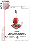
The 225 cutting-off machine with circular blade for ferrous metals produced by MIVA is made from a solid casting,
carefully processed . The upper surface, designed to allow the complete draining away of the cutting fluid, has been
processed using precision machinery to allow the attachment of a sturdy vice with burr-proof jaws.
The bar-stop device allows the length required to be preset and a constant level of performance for repeated cuts.
The blade-holding head is firmly attached to a reduction unit in oil bath built onto the motor and to the base by means of
a joint which provides 45° rotation to left and the cutting movement with manual feed.
The main switch is located above the motor block.
The control lever, fitted with an ergonomic hand-grip and blade activation button with safety release action, reduces
fatigue during operation to a minimum.
The blade is protected by a guard which in its turn protects the operator from ejected shavings and coolant.
The machine is supplied with a set of service spanners.
4.3 INTENDED AND UNSUITABLE USES OF THE MACHINE
The 225 cutting-off machine with circular blade has been designed and built to cut bars, structural steel and
ferrous metal pipes in accordance with the instructions contained in this manual.
Therefore, the cutting of other materials is not permitted: if the above recommendations are not observed, the
machine could be damaged and the health and safety of the operator put at risk.
Cutting is not permitted, if the bar has not been first locked in the vice.
5. MAIN TECHNICAL DATA
Under no circumstances should the following data be altered, this is in order to protect the correct functioning
of the machine and to avoid creating safety risks for the operator.
MOTOR
single-phase
Motor Power
single-phase KW 0,75
Motor revolutions (two speeds)
1400 rpm
CIRCULAR BLADE (SAW)
Number of teeth and feed holes according to table
Maximum diameter and thickness
Diameter: 225 mm
Thickness: 2
BLADE REVOLUTIONS per minute
52 rpm
CUTTING ANGLE
45° right
PIECE LOCKING VICE: MAX OPENING
70 mm
COOLANT TANK CAPACITY
litres 1
MACHINE WEIGHT
Kg 32 - N 310
6. MACHINE INSTALLATION
A. MACHINE CHECK AND CONTROL LEVER ASSEMBLY
The machine should be checked to make sure that it has not been damaged during transportation and handling. Keep
the machine in its normal position and avoid turning it upside down.
Control lever assembly (drawing 4 Encl. 2) : Fit the supplied head lever 22, into position 20 and fasten it by means of the
nut 72. To fit the handle, connect the electric cable terminals 220 to the microswitch 218 and place it in the left second
half of the handle as shown in draw. 3 Encl.2. Then insert the button 222 and the lever 22. Complete the assembly using
the screws 221 and then 219. Make sure that the cable is inserted into the lever slot 22, after having checked that there
are no burrs or sharp edges in the slot.
B. ASSEMBLY OF CIRCULAR BLADE
For the assembly of the circular blade, remove the screw No. 34 (Draw. 5 Encl. 2), keeping the motor-blade block raised
and rotate the mobile guard 31 backwards. Unscrew the screw 29 counter clock wise, withdraw the flange 28, insert the
circular blade, making sure that the toothing faces the same direction as the arrow on the mobile guard. Then refit flange
28 and screw 29.
C. ELECTRICAL CONNECTION TO THE MAINS
Install a differential thermomagnetic switch with characteristics suited to the mains.
Make sure that the power supply voltage corresponds to the voltage on the motor plate. Connect the cable to the power
supply line observing the colour codes of the individual wires, pay particular attention to the earth wire. Connect the
machine, make sure that the rotation of the circular blade is in the direction shown by the arrow on the guard.
D. CUTTING COOLANT
For the cooling of the circular blade, fill the tank with emulsible oil obtained from a mixture of water and AGIP ULEX 260
EP oil with a percentage of 5-7%
7. MACHINE START UP AND OPERATION
7.1 DEVICES AND THEIR LOCATION
(The location of the devices described is shown on the 225 installation plan Encl. 1)
Code
42
LOCKABLE MAIN SWITCH
Code
218
START-STOP MICROSWITCH: situated inside the handle located at the end of the control
lever and has safety release action.
Code
59
CUTTING ANGLE DEVICE: to check that cutting inclination is as required
Code
9
LOCKING VICE
Code
65
BAR-STOP
Code
22
CONTROL LEVER WITH HANDLE
7.2 TOOLS SUPPLIED
1
Allen wrench size 3
1
Allen wrench size 4
1
Allen wrench size 5
1
Allen wrench size 6
1
Allen wrench size 14
7.3 OPERATION
CHECKS TO CARRY OUT BEFORE EACH CUT
A.
Make sure that the circular blade is fastened securely by means of screw 29 (DRAW.5 ENCL.2)
B.
Check that the hand indicates the required cutting angle (vice scale)
C.
Make sure that the head and vice are locked by means of the lever 52 (DRAW.6 ENCL.3)
D.
With the motor off, lower the head and check that at the end of the stroke, the circular blade does not touch
the bench 2. If the circular blade does touch, adjust the screw 67 (DRAW.4 ENCL.2).
E.
Make sure that the piece to be cut is adequately secured in the vice.
F.
Make sure that the coolant is circulating in the machine.
CUTTING OPERATION
A.
Before each cutting operation, if the cutting inclination is not as required, correct or change the inclination by
loosening the screw 52 (DRAW.6 ENCL.3) and after correction, securing the screw again.
B.
Clamp the piece to be cut by means of the handwheel 7, press the main switch 42, take hold of the handle 25
located at the end of the head lever and press button 218. The blade will now start turning.
C.
Position the blade carefully on the piece to be cut. Then increase the pressure in order to accelerate the
cutting operation without using excessive force. To make a series of cuts, position the bar-stop 65 at the size
required. Fix it into position by using the knob 66.
D.
To replace the circular blade carry out the same operations used to assemble the circular blade. (chapter 7c).
E.
For the choice of most suitable blade consult the table ENCL. 1.
We strongly discourage the use of blades with ruined or insufficiently sharp cutting edges
7.4 SPECIAL SAFETY CHECKS
A. Before using the machine, check carefully that the safety devices are in good working order, that the mobile parts are
not blocked, that no parts are damaged and that all the components are installed correctly and are functioning properly.
B. Make sure, before operating the machine, that the screws of the guards and other protective devices are
adequately secured, especially the screws on the circular blade guard and the rotation levers of the circular
blade mobile guard.
C. Check that the safety microswitches are functioning correctly.
D. Make sure that the mobile guard does not leave uncovered an angle of more than 5° in order to prevent
fingers from entering.
E. Pay attention to environmental conditions. Do not expose the machine to rain; to not use it in damp environments,
position the machine on a clean dry floor that has no oil or grease stains.
F. Before using the machine, the operator should make sure that all tools and service spanners used for maintenance or
adjustment have been removed.
7.5 GENERAL SAFETY RULES
A. Wear appropriate clothing. The operator's clothing should not be loose or dangling nor should it have parts which
could easily get caught.
B. Avoid unstable operating positions. Find a safe and evenly balanced position to operate the machine.
C. Keep the work area tidy, untidiness increases the risk of accidents.
D. Do not use the power supply cable to disconnect the plug from the socket. Protect the cable from high temperatures,
oil or sharp edges. For outdoor use, only use extension cables which are in line with current regulations.
7.6 MEASURES TO PREVENT RESIDUAL RISKS
A. The removal of guards and tampering with the safety devices is strictly forbidden.
B. Gloves should always be worn.
C. Standard work clothing should be used and kept closed and should not have flapping parts.
D. The machine should not be cleaned with liquids under pressure.
E. In the event of fire, extinguishers should not be used unless they are the powder type. The electric power supply to the
machine should always be disconnected in these circumstances.
F. Do not insert foreign bodies into the motor cover and to not supply the machine with voltage by tampering with the
safety microswitches or main switch.
G. Take the necessary precautions to avoid the machine being started by other people during loading,
adjustment, piece changing or cleaning.
8. MAINTENANCE AND REPAIRS
8.1 GENERAL SAFETY MEASURES
A. Before carrying out any work on electrical equipment, remove the power supply plug from the control panel
(disconnect voltage).
B. Only use cables to supply power, which have a cross-section suited to the power of the machine.
C. Repairs should only be carried out by authorized personnel. Only spare parts made by the original manufacturer
should be used, otherwise these could cause damage or injury.
8.2 ROUTINE CHECKS AND MAINTENANCE
FREQUENCY
(working hours)
1000 hours
1000
50
OPERATION
Replace the oil in the gear box with AGIP ACER 320 oil (0.2 litres) or equivalent.
Lubrication of mobile parts in the piece locking vice (GREASE AGIP MU 2)
Cleaning of the coolant tank and filter check
8.3 DESCRIPTION OF ROUTINE MAINTENANCE
A. Replacement of gear box oil
Remove caps 38 and 19 (draw.6 Encl.3), let all the used oil flow out into a container which should have a label indicating
the contents for the purposes of disposal. Replace cap 19. Feed 0.2 litres of oil (as specified above) into the
oil feed hole located on the upper part of the gear box and then replace cap 38.
B. Lubrication of mobile parts of piece locking vice
Clean and grease the parts worked by the bench 2 , the vice 9 and the vice screw 6.
C. Cleaning of the coolant tank: Filter check.
Empty the coolant from the tank by means of the tap located on the rear part of the machine bench (after moving the
liquid feed pipe away from this). Collect the coolant in a container for future disposal. Clean out the shavings and the
metallic powder, taking care not to scatter this over the machine especially around the motor and the box containing the
electrical equipment. Reconnect the pipe, check filter 44 and if necessary replace it. Fill the tank with the amount and
liquid stated previously.
9.INFORMATION REGARDING ENVIRONMENTAL NOISE
An environmental noise test carried out on the 225 cutting-off machine with circular blade, identical to the
machine to which these operation instructions refer, has given the following results:
ACOUSTIC RADIATION PRESSURE
1.
LAeq = 84.2 dB (A)
2.
Lpeak = 90.6 dB (the maximum acceptable value is 140 dB).
3.
The level of background noise has no influence = 48.5-54.2 dB (A)
10. LIST OF SPARE PARTS
POS.
1
2
3
4
5
6
7
8
9
10
11
12
13
14
15
16
17
18
19
20
21
22
23
24
25
26
27
28
29
30
31
32
33
34
35
36
37
38
39
40
41
42
43
44
45
DESCRIPTION
Bench
CODE
002/25
Pin 8x26 DIN 6325
Vice screw
Vice handwheel
Head carrying arm
Vice jaw
Dowel M8x10 DIN 915
Vice cover
HSHC screw M5x8 DIN 912
HSHC screw M6x20 DIN 912
Bush
Belleville washer 16x8,2x1,2 DIN2093
Pump pushing stud
Pump stud braket
O- Ring 3100
Oil level plug 3/8”
Head
Spacer
Head lever
Helical gear
Pin 6x40 DIN 1
Head lever handle
Disk shaft
Disk
Disk flange
Disk fastening screw
Disk guard
Disk movable guard
Snap ring D.45 E DIN 471
HSHC screw M6x16 DIN 912
HSHC screw M6x16 DIN 912
Disk movable guard movable rod
Disk movable guard fixed rod
HSHC screw M6x16 DIN 912
Oil filling cap 3/8”
Key 5x5x30 DIN 6885
Dowel M8x35 DIN 914
Switch box
Switch
Motor
Filter
Splash
012/25
014/25
004/25
013/25
015/25
027/25
020/25
019/25
045/25
006/25
044/25
039-A/05
010/25
046/05
011/25
017/05
029/25
007/25
008/25
POS.
DESCRIPTION
46
47
48
49
50
51
52
53
54
55
56
57
58
59
60
61
62
63
64
65
66
67
68
69
70
71
72
73
74
75
76
77
Bearing
Worm screw
Self-locking ring nut M16x1DIN 981
Water pipe
HSHC screw M4x6 DIN 912
Pump carrier braket
HH screw M10x40 DIN 933
Washer D.10 DIN 125/A
Dowel 6x10 DIN 914
Rotor shaft
Stator
Head pin
HH screw M6x16 DIN 933
Graduated sector
Splash guard 25-35-7
Stopper
Head gear
Nut M 16 DIN 934
Bar stopper rod
Bar stopper
Bar stopper knob
HH screw M6x30 DIN 933
Pump
Rear guard
Nut M8 DIN 934
Nut M6 DIN 934
Nut M14 DIN936
Motor casing
Motor flange
Snap ring
Nut M6 DIN 934
Pring pin 6x16 DIN1481
218
219
220
221
222
Micro switch of handle
HSFHC screw M4x8 DIN7991
Electrical cable 2x1
RH screw M2,9x13 DIN7981
Button
CODE
009/25
018/25
032/25
023/25
046/25
024/25
035/25
031/05
037/25
077/25
022/25
028/25
026/25
025/25
001/80
042/25
028/90