1
Iris Reader
Operating Instructions
Model No.
reject
BM-ET200
accept
BM-ET200
Before attempting to connect or operate this product,
please read these instructions carefully and save this manual for future use.
The model numbers in these Operating Instructions are given without suffix.
WARNING:
• This apparatus must be earthed.
• To prevent fire or electric shock hazard, do not expose this
apparatus to rain or moisture.
• The apparatus should not be exposed to dripping or splashing
and that no objects filled with liquids, such as vases, should be
placed on the apparatus.
• All work related to the installation of this product should be
made by qualified service personnel or system installers.
• For PERMANENTLY CONNECTED APPARATUS provided
neither with an all-pole MAINS SWITCH nor an all-pole circuit
breaker, the installation shall be carried out in accordance with
all applicable installation rules.
• The connections should comply with local electrical code.
Cautions:
• This unit is for indoor use only.
• Refer to the name plate on the bottom of this product to
verify identifications and power ratings.
CAUTION
RISK OF ELECTRIC SHOCK
DO NOT OPEN
CAUTION: TO REDUCE THE RISK OF ELECTRIC SHOCK,
DO NOT REMOVE COVER (OR BACK).
NO USER-SERVICEABLE PARTS INSIDE.
REFER SERVICING TO QUALIFIED SERVICE PERSONNEL.
The lightning flash with arrowhead symbol,
within an equilateral triangle, is intended to
alert the user to the presence of uninsulated
"dangerous voltage" within the product's
enclosure that may be of sufficient magnitude to constitute a risk of electric shock to
persons.
The exclamation point within an equilateral
triangle is intended to alert the user to the
presence of important operating and maintenance (servicing) instructions in the literature accompanying the appliance.
2
We declare under our sole responsibility that the product to which this
declaration relates is in conformity with the standards or other normative
documents following the provisions of Directives 2006/95/EC and
2004/108/EC.
Wir erklären in alleiniger Verantwortung, daß das Produkt, auf das sich
diese Erklärung bezieht, mit der folgenden Normen oder normativen
Dokumenten übereinstimmt. Gemäß den Bestimmungen der Richtlinie
2006/95/EC und 2004/108/EC.
Nous déclarons sous note seule responsabilité que le produit auquel se
réfère la présente déclaration est conforme aux normes ou autres
documents normatifs conformément aux dispositions des directives
2006/95/CE et 2004/108/CE.
Nosotros declaramos bajo nuestra única responsabilidad que el
producto a que hace referencia esta declaración está conforme con las
normas u otros documentos normativos siguiendo las estipulaciones de
las directivas 2006/95/CE y 2004/108/CE.
Noi dichiariamo sotto nostra esclusiva responsabilità che il prodotto a
cui si riferisce la presente dichiarazione risulta conforme ai seguenti
standard o altri documenti normativi conformi alle disposizioni delle
direttive 2006/95/CE e 2004/108/CE.
Wij verklaren als enige aansprakelijke, dat het product waarop deze
verklaring betrekking heeft, voldoet aan de volgende normen of andere
normatieve documenten, overeenkomstig de bepalingen van Richtlijnen
2006/95/EC en 2004/108/EC.
Vi erklærer os eneansvarlige for, at dette produkt, som denne
deklaration omhandler, er i overensstemmelse med standarder eller
andre normative dokumenter i følge bestemmelserne i direktivene
2006/95/EC og 2004/108/EC.
Vi deklarerar härmed värt fulla ansvar för att den produkt till vilken
denna
deklaration
hänvisar
är
i
överensstämmelse
med
standarddokument, eller andra normativa dokument som framställs i
direktiv nr. 2006/95/EC och 2004/108/EC.
Ilmoitamme yksinomaisella vastuullamme, että tuote, jota tämä ilmoitus
koskee, noudattaa seuraavia standardeja tai muita ohjeellisia asiakirjoja,
jotka noudattavat direktiivien 2006/95/EC ja 2004/108/EC säädöksiä.
Vi erklærer oss alene ansvarlige for at produktet som denne erklæringen
gjelder for, er i overensstemmelse med følgende normer eller andre
normgivende dokumenter som følger bestemmelsene i direktivene
2006/95/EC og 2004/108/EC.
The serial number of this product may be found on the bottom of the unit.
You should note the serial number of this unit in the space
provided and retain this book as a permanent record of your
purchase to aid identification in the event of theft.
Model No.
Serial No.
Important Safety Instructions
1) Read these instructions.
2) Keep these instructions.
3) Heed all warnings.
4) Follow all instructions.
5) Do not use this apparatus near water.
6) Clean only with dry cloth.
7) Do not block any ventilation openings. Install in accordance with the manufacturer's instructions.
8) Do not install near any heat sources such as radiators, heat registers, stoves, or other apparatus (including amplifiers) that
produce heat.
9) Do not defeat the safety purpose of the polarized or grounding-type plug. A polarized plug has two blades with one wider
than the other. A grounding type plug has two blades and a third grounding prong. The wide blade or the third prong are
provided for your safety. If the provided plug does not fit into your outlet, consult an electrician for replacement of the
obsolete outlet.
10) Protect the power cord from being walked on or pinched particularly at plugs, convenience receptacles, and the point
where they exit from the apparatus.
11) Only use attachments/accessories specified by the manufacturer.
12) Use only with the cart, stand, tripod, bracket, or table specified by the manufacturer, or sold with the apparatus. When a
cart is used, use caution when moving the cart/apparatus combination to avoid injury from tip-over.
S3125A
13) Unplug this apparatus during lightning storms or when unused for long periods of time.
14) Refer all servicing to qualified service personnel. Servicing is required when the apparatus has been damaged in any way,
such as power-supply cord or plug is damaged, liquid has been spilled or objects have fallen into the apparatus, the
apparatus has been exposed to rain or moisture, does not operate normally, or has been dropped.
3
Limitation of Liability
THIS PUBLICATION IS PROVIDED "AS IS" WITHOUT WARRANTY OF ANY KIND, EITHER EXPRESS OR IMPLIED,
INCLUDING BUT NOT LIMITED TO, THE IMPLIED WARRANTIES OF MERCHANTABILITY, FITNESS FOR ANY PARTICULAR PURPOSE, OR NON-INFRINGEMENT OF THE
THIRD PARTY'S RIGHT.
THIS PUBLICATION COULD INCLUDE TECHNICAL INACCURACIES OR TYPOGRAPHICAL ERRORS. CHANGES
ARE ADDED TO THE INFORMATION HEREIN, AT ANY
TIME, FOR THE IMPROVEMENTS OF THIS PUBLICATION
AND/OR THE CORRESPONDING PRODUCT (S).
Disclaimer of Warranty
IN NO EVENT SHALL MATSUSHITA ELECTRIC INDUSTRIAL CO,. LTD. BE LIABLE TO ANY PARTY OR ANY PERSON, EXCEPT FOR REPLACEMENT OR REASONABLE
MAINTENANCE OF THE PRODUCT, FOR THE CASES,
INCLUDING BUT NOT LIMITED TO BELOW:
(1) ANY DAMAGE AND LOSS, INCLUDING WITHOUT LIMITATION, DIRECT OR INDIRECT, SPECIAL, CONSEQUENTIAL OR EXEMPLARY, ARISING OUT OF OR
RELATING TO THE PRODUCT;
(2) PERSONAL INJURY OR ANY DAMAGE CAUSED BY
INAPPROPRIATE USE OR NEGLIGENT OPERATION
OF THE USER;
(3) UNAUTHORIZED DISASSEMBLE, REPAIR OR MODIFICATION OF THE PRODUCT BY THE USER;
(4) INCONVENIENCE OR ANY LOSS ARISING OUT OF
NON-RECOGNITION WHEN IRIS DATA IS ALREADY
ENROLLED, DUE TO ANY REASON OR CAUSE OTHER
THAN ANY FAILURE OR PROBLEM OF THE PRODUCT;
(5) ANY PROBLEM, CONSEQUENTIAL INCONVENIENCE,
OR LOSS OR DAMAGE, ARISING OUT OF THE SYSTEM COMBINED BY THE DEVICES OF THIRD PARTY;
(It might be a case that the entrance-gate control system, for example, combining the Product and the electric lock devices, does not open/close the door properly
because of before-mentioned reasons or other causes
of such system except for the Product.)
4
(6) ANY LOSS OR DAMAGE, OR CLAIMS ARISING OUT
FROM LOSS OR LEAK OF PC DATA INCLUDING IRIS
DATA IN THE IRIS SERVER PC, IC CARD, OR MEMORY;
(Iris data is nature of privacy. The customer shall be
responsible for any Iris data stored in the iris server
PC.)
(7) INCONVENIENCE OR ANY LOSS ARISING WHEN
IMAGES ARE NOT DISPLAYED, DUE TO ANY REASON
OR CAUSE INCLUDING ANY FAILURE OR PROBLEM
OF THE PRODUCT;
(8) ANY CLAIM OR ACTION FOR DAMAGES, BROUGHT
BY ANY PERSON OR ORGANIZATION BEING A PHOTOGENIC SUBJECT, DUE TO VIOLATION OF PRIVACY
WITH THE RESULT OF THAT SURVEILLANCE-CAMERA'S PICTURE, INCLUDING SAVED DATA, FOR SOME
REASON, BECOMES PUBLIC OR IS USED FOR THE
PURPOSE OTHER THAN SURVEILLANCE.
Network Security
As you will use this product connected to a network, your attention is called to the following security risks.
1. Leakage or theft of information through this product
2. Use of this product for illegal operations by persons with malicious intent
3. Interference with or stoppage of this product by persons with malicious intent
It is your responsibility to take precautions such as those described below to protect yourself against the above network
security risks.
• Use this product in a network secured by a firewall, etc.
• If this product is connected to a network that includes PCs, make sure that the system is not infected by computer
viruses or other malicious entities (using a regularly updated anti-virus program, anti-spyware program, etc.).
• Protect your network against unauthorized access by restricting users to those who log in with an authorized user
name and password.
• Apply measures such as user authentication to protect your network against leakage or theft of information, including
iris data, authentication information (user names and passwords), and alarm mail information.
Trademarks and Registered Trademarks
• Microsoft, Windows, Windows Server, ActiveX and Internet Explorer are either registered trademarks or trademarks of
Microsoft Corporation in the United States and/or other countries.
• Adobe and Reader are either registered trademarks or trademarks of Adobe Systems Incorporated in the United States
and/or other countries.
• Intel and Pentium are trademarks or registered trademarks of Intel Corporation or its subsidiaries in the United States and
other countries.
• Private idTM is a trademark of Iridian Technologies in the United States.
• Other names of companies and products contained in these operating instructions may be trademarks or registered trademarks of their respective owners.
5
CONTENTS
Important Safety Instructions ...............................................3
Limitation of Liability ............................................................4
Disclaimer of Warranty ........................................................4
Network Security .................................................................5
Trademarks and Registered Trademarks ...........................5
Preface ................................................................................7
■ System Configuration of Stand-alone Mode .................7
■ System Configuration of Network Mode .......................7
Features ...............................................................................9
Precautions ........................................................................10
Document Convention .......................................................12
Notification About This Document .....................................14
Major Operating Controls and Their Functions .................15
■ External View ..............................................................15
■ Rear View ....................................................................16
■ Internal View ...............................................................17
■ Specifications of Connector Terminal .........................17
■ Specifications of Setup Switches ...............................20
Installation and Connections .............................................23
■ Preparation .................................................................24
■ Description about Tamper Detection .........................25
■ Notification about the Installation Site ........................25
■ Installation Space and Recognition Range ................26
■ Installation ...................................................................28
Setup (Stand-alone Mode) ................................................32
■ Available External Devices .........................................32
■ List of Settings ............................................................32
■ Connection and Setup Flow .......................................34
■ Registering Administrators .........................................36
■ Registering Users with the Operator’s Privilege .........37
■ Setup from the Web Browser on the PC .....................37
■ About the Operation Window .....................................39
■ Configure the Settings Relating to System
[Reader Setting] .........................................................40
■ Operation from the Web Browser on the PC ..............41
6
■ Configure the Settings Relating to User
[User/Administrator] ...................................................41
■ Check the Logs [Log] .................................................45
■ Back up or Restore Files ............................................48
■ Configure the Settings Relating to Time and Date
[Time & Date] ..............................................................50
■ Check the Version of Iris Reader Software
[Version] .....................................................................50
■ Download Files [Download] ........................................51
■ Operations from the Numeric Key
(For Use with Stand-Alone Mode Only) ......................53
Setup (Network Mode) ......................................................63
■ Connection and Setup Flow .......................................63
■ Registering Administrators .........................................64
■ Setup from the Web Browser on the PC .....................64
■ About the Operation Window .....................................65
Instructions for Proper Enrollment and Recognition ..........67
Operating Procedures (Instructions for Users) .................68
■ How to Position Your Eyes in the Mirror ......................68
■ If You Have Difficulty in Eye Positioning .....................69
■ If You are Wearing an Eyepatch, etc. .........................69
■ Cases of Enrollment/Recognition Failure ....................70
■ How to Carry Out Enrollment (Network Mode) ...........70
■ How to Carry Out Enrollment (Stand-alone Mode) .....71
■ How to Carry Out Iris Reader Recognition .................73
■ Recognition by an Iris Reader and a Card Reader ....74
■ How to Carry Out PIN Recognition
(For Use with Stand-Alone Mode Only) ......................75
List of System Log Information ...........................................78
Troubleshooting .................................................................80
■ When Enrollment/Recognition Becomes Invalid .........80
■ Before Requesting for Repair .....................................81
Specifications ....................................................................83
Standard Accessories .......................................................84
Preface
Iris Reader BM-ET200 is used in an access control system. The iris reader, which captures a user's iris image, is available for
the following operation modes.
• Stand-alone mode: The iris reader can be used in the stand-alone operation.
• Network mode: Iris server is required to operate the iris server.
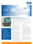
■ System Configuration of Stand-alone Mode
It is possible to enroll and recognize iris data by using this iris reader in the stand-alone operation.
Numeric key (option) or web browser is used for iris reader control.
Iris data of up to 50 users can be enrolled to the iris reader.
Access control panel
Form A contact
output
Setup PC*
Iris reader
LAN
clear
7
=
8
/
*
9
–
4
5
6
+
1
2
3
0
,
.
enter
Numeric key*1
Electric lock
LAN connection
Numeric key connection
Form A contact connection
* Use PC that operates Microsoft® Internet Explorer® 6.0 SP2 (for Microsoft®
Windows® XP Professional SP2) or Microsoft® Internet Explorer® 6.0 SP1
(for Microsoft® Windows® 2000 Professional SP4).
■ System Configuration of Network Mode
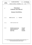
• As an enrollment iris reader for iris image capturing and iris server enrollment
To activate iris recognition, it is necessary to capture the iris images of a user and enroll the iris data in the iris server.
An iris reader generates iris data from iris images captured, and transfers the data to the iris server in the LAN (Local Area
Network). The iris data is enrolled in the iris database of the iris server. Up to 10 025 users can enroll their iris data. *1
*1 For operation in the network mode, you need to install the optional Administration Software BM-ES200. The PC needs to
have Microsoft® Windows® operating system installed.
The total number of users that can be enrolled differs depending on the total licence numbers of the User Licence Software
BM-EU30000E Series.
• As a recognition iris reader for iris recognition
Iris data of up to 5 025 users can be distributed from the iris server to iris readers. If the iris data of user has been distributed to a recognition iris reader, or if a card reader (connected to a recognition iris reader) reads the iris data out of a card,
the iris reader can recognize the user in approx. 0.3 seconds after iris image capturing.*2 The user can check the recognition result with the result indicator (accept/reject) on the front panel of the iris reader.
7
Enrollment
For enrollment*10
Captures iris images of both eyes, generates iris data from
the iris images, and enrolls the iris data in the iris server. *3
If a card writer is connected to the iris server, iris data
enrolled in the iris server can be written into a card. *4
Iris server
Card writer
Enrolled iris data is distributed
to iris readers.
Recognition
If no corresponding iris data
has been found in
the iris reader, the iris
reader accesses the
administration software to
execute server certification.
For recognition*7
(1) Captures the iris images of both eyes.
(2) Recognizes a user by checking the iris
images with the iris data (that is
distributed to the iris reader or that is read
out by the card reader connected to the iris
reader). *6
(3) Indicates the recognition result.
Administration Software BM-ES200*5
User Licence Software BM-EU30000E Series
Iris database
*2 The recognition time may differ depending on capturing conditions.
*3 The iris reader captures the iris images of both eyes at the same time, but the iris data of each eye is enrolled separately.
Enrollment/recognition by one eye capturing is also available.
*4 Refer to BM-ES200 Operating Instructions
(supplied with Administration Software BM-ES200) for details on available cards and card writers.
*5 Capturing diagnosis is made by the administration software at the time of enrollment.
*6 The user is recognized with the iris data of either eye.
*7 Up to 256 iris readers (enrollment and recognition iris readers) can be connected to the iris server in the LAN.
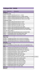
• Iris recognition technology is a way to identify a person with iris patterns (an iris is the thin
plate-shaped film in front of the eyeball), which differ among each person. The iris pattern of
the left eye differs from that of the right eye.
• Using iris readers, users can carry out recognition without touching any devices.
• In the iris recognition process, the users are recognized with the enrolled iris data.
Iris
Retina
Pupil
8
Features
• Automatic guidance and recognition by voice guidance and distance indicator
When a user is within 50 cm {1.64 ft.} of the front of an iris reader, the voice guidance will start. Moving to the point where
the user can see both eyes in the mirror according to the voice guidance or distance indicator, the user's iris images will
be automatically captured and the user will be recognized from the iris data. The recognition range of the iris reader is
between approx. 30 cm {0.98 ft.} and 40 cm {1.32 ft.}
• One-time capturing of both eyes enables recognition in approx. 0.3 seconds*1
This iris reader captures the iris images of both eyes at the same time, generates iris data from the iris images, and compares the data with that distributed to the recognition iris reader or that read out by the card reader connected to the iris
reader. If the iris data of either eye is corresponding with the iris data that is distributed or that is read out, you will be recognized as an enrolled user. The recognition time will be approx. 0.3 seconds after iris image capturing.*1
If no corresponding iris data is found in the recognition iris reader, the iris reader will transfer the data to the iris server. The
iris server will compare the transferred iris data with those enrolled in the iris database for certification. (In this document,
the certification by the iris server is called "server certification".) The recognition time will be approx. 5 seconds after iris
image capturing.*2
*1 The recognition time may differ depending on capturing conditions.
*2 The recognition time may differ depending on the traffic of the network or the total number of the enrolled users.
• Option camera can be installed. (BM-ETC202: Not supplied to the iris reader)
Optional minisize colour camera can be installed in the iris reader. You can record the facial image of a user by connecting
this camera and a recorder. Using the recognition result outputs (REJECT) of the iris reader, you can record only users that
have not been recognized.
• Access control system can be composed.
Iris readers and the iris server can compose an access control system in combination with access control panels*3, card
readers*3, and electric locks*3, etc.
*3 These devices are independent to BM-ET200.
• Supporting a common access control interface (BM-ETA201: Not supplied to the iris reader)
Recognition result outputs support Wiegand/RS-485*4, which is one of the interfaces commonly used for access control
systems. Any access control panel supporting the Wiegand/RS-485 interface can be directly connected to the iris reader.
The iris reader also has a Wiegand/RS-485 input. Any card reader supporting the Wiegand/RS-485 interface can be directly connected to the iris reader for composing an access control system.
*4 Our exclusive protocol is employed.
• Recognition is available using a card that includes iris data
By using the iris server and a card writer, you can write the iris data of user into a card. When the user passes the card
through the card reader connected to an iris reader, recognition is available.
9
Precautions
General safety requirement:
For Installation
Refer all work related to the installation of the apparatus to
qualified service personnel or system installers.
Consult an expert for help in evaluating load bearing
capacity of the installation surface and structure. If the surface is not strong enough, the apparatus may fall down.
Refer to the apparatus specifications for weights.
To avoid fire or personal injury:
• Do not drop metallic parts through slots.
This could permanently damage the apparatus.
• Do not attempt to disassemble the apparatus.
There are no user-serviceable parts inside. Panasonic
is not responsible for regulatory compliance of a disassembled Panasonic apparatus by unauthorized personnel. Contact qualified service personnel for maintenance.
• Do not strike or shake the apparatus.
Handle the apparatus with care, or it could cause the
trouble of it.
• Do not expose nor operate the apparatus in
wet/damp conditions.
Take immediate action if the apparatus gets wet. Refer
servicing to qualified service personnel. Moisture could
damage the apparatus and also cause electric shocks.
• Do not use strong or abrasive detergents when
cleaning the apparatus.
Use soft and dry cloth to clean the apparatus when it is
dirty. When the dirt is hard to remove, use a mild detergent and wipe gently.
• Do not use the apparatus beyond operating requirements.
It is designed to operate properly for environment specified below:
Temperature
0 °C to +40 °C {32 °F to 104 °F}
Humidity
30 % to 90 % relative humidity, noncondensing
Source voltage
12 V DC/24 V DC
Important notes specific to the apparatus:
• This unit has no power switch.
Power is supplied from an external 12 V DC/24 V DC
power-supply device. Refer to service personnel for
how to turn on/off the power.
Note: While the power is turned off, recognition and
entrance will NOT be available.
10
• The third-party external power supply should meet
the specifications. (Refer to p. 83.)
• Adopting tamper-proof structure.
Refer to service personnel for relocating or servicing
the apparatus.
As the unit has been designed in tamper-proof structure, buzzer sound will be activated with alarm notification when you try to open the front cover or detach the
apparatus from the wall. Then, recognition will become
unavailable, the alarm notification will also be sent to
the iris server, and the stored data (user information
and reader settings) may be erased from the unit.
• Use of near-infrared ray
Near-infrared ray is used when iris data are captured
by the apparatus. The near-infrared ray is compliant
with the radiological safety standard of IEC60825-1.
• Indication label
Refer to the indication placed on the bottom of the
apparatus as to the indications of equipment classification and power source, etc.
• This apparatus is not designed to prevent theft.
The apparatus is designed to perform roles of capturing
personal iris data, of recognizing individuals and of producing output signals only. To ensure your
entrance/gate security, you must use the apparatus
together with other security system or devices including
electric locks.
Panasonic is NOT RESPONSIBLE FOR ANY CRIME OR
TROUBLE CAUSED BY USING THIS APPARATUS.
• In some cases, recognition or enrollment doesn't
work properly.
It could be invalid in recognition or enrollment when the
apparatus has difficulty in getting iris information due to
dirt in front of lens, reflection of glasses or insufficiency
of physical requirement.
• Iris data is a nature of privacy.
Take enough care not to leak the data out of the iris
server. It is also recommended that you should get an
agreement from a person to register his or her data.
• The settings of this apparatus are configured by the
setup PC or iris server.
The operational setting of stand-alone mode is configured using the setup PC. The operational setting of network mode is configured using the optional
Administration Software BM-ES200, which is to be
installed in the iris server.
Depending on the settings, the voice guidance will not
be output or the live indicator will be off at all times.
Refer to system administrators for details on settings.
* If the previous version of Administration Software (BMES300, BM-ES300A, or BM-ES330) is installed on the
iris server, you cannot set up iris readers or distribute
iris data from the iris server to iris readers.
• Take care not to pinch your hands or fingers
between the front panel and the body of this apparatus. That may cause injury.
• When the front panel is damaged, refer to the dealer.
It may affect iris image capturing and cause invalid
recognition.
• Avoid placing a receptacle that contains liquid such
as water.
When the liquid falls over the apparatus, it may cause a
fire or electric shock.
• Follow all instructions. Otherwise, our liability will
be limited.
For details, refer to "Limitation of Liability" (p. 4).
• Time adjustment
This apparatus has the inner clock. In the network
mode, the time of inner clock is synchronized to the iris
server once every hour.
While this apparatus is being used in the stand-alone
mode, adjust the inner clock time manually, or connect
this apparatus to an external master clock by using
Option Board BM-ETA201 (not supplied).
The time gap of 1 minute or more per month might be
caused by operating conditions.
11
Document Convention
Stand-alone mode: In this mode, the iris reader can be used in the stand-alone operation. Iris server is not required. The maximum number of users that can be registered is 50.
The users are registered with the numeric key. Registration from the browser installed on the setup PC is also available.
Network mode: In this mode, iris server is used for connection with the iris reader. The administration software, iris server, and
network connection are required. The number of users that can be registered in the iris server is 25 to 10 025.
Access control system: The system that controls access through iris recognition by iris readers and an iris server, together
with access control panels, card readers, and electric locks, etc.
Administration Software: Panasonic Administration Software BM-ES200 (This software is sold separately, however, it must be
used in combination with iris readers when the iris reader is used in the network mode.)
This software is used for administering iris enrollment/recognition. The total number of users that can be registered differs
depending on the total licence numbers of User Licence Software BM-EU30000E Series (This software is sold separately,
however, it must be used in combination with iris readers.). If User Licence Software BM-EU30000E Series is not installed
on the iris server, up to 25 users can be enrolled.
Distribution: To transfer enrolled data from the iris server to iris readers and to save the data in the iris readers
Enrollment: To save a user's iris data associated with the individual information (name and ID data, etc.) in the iris server
Iris data is enrolled using this iris reader or the administration software.
High speed serial interface: Connector that expands the functions of iris reader
Numeric key or external storage device can be connected.
ID data: The data, which is enrolled with each user's information in an access control system with a card reader
Iris reader: Panasonic Iris Reader BM-ET200
Iris data: Data that are generated from captured iris images
Iris recognition: Way to identify a person with iris patterns, which differ between each person
Iris server: PC in which the following applications are installed
The iris server can administer all the iris readers connected in the LAN.
• Administration Software (BM-ES200)
• User Licence Software (BM-EU30000E Series)
Option board (Model NO.: BM-ETA201): Board that is connected to external devices supporting the Wiegand/RS-485 interface. When the iris reader is used in the stand-alone mode, the Wiegand/RS-485 interface is unavailable.
Option camera (Model NO.: BM-ETC202): Camera that captures the facial image of a user.
PIN recognition: Recognition carried out by comparing the ID and PIN (Personal Identification Number) entered from the
numeric key with those enrolled in the database of iris reader. This way of certification can be applied when iris recognition
is unavailable.
Recognition: To identify a user by comparing the iris data generated (from iris images captured) with the data enrolled in the
iris database or read out of a card
Server certification: Certification carried out by the iris server when no corresponding iris data is found in iris readers
The iris reader generates iris data from the iris images captured. Then, the iris data is transferred to the iris server in the
LAN, which carries out certification. The setting in the administration software will determine whether to carry out server
certification.
User Licence Software: Panasonic User Licence Software BM-EU30000E Series that is required to enroll iris data
You need to purchase the software which supports the total number of users enrolled. (Administration Software BM-ES200
supports 25 user licences.)
• For 100 users: BM-EU30100E
• For 1 000 users: BM-EU31000E
• For 3 000 users: BM-EU33000E
• For 5 000 users: BM-EU35000E
Voice guidance: One of the methods to guide the eyes of users to the capturing range
Voice guidance leads users with the voice output from the speaker of the iris reader.
The setting of voice guidance will be configured by the system administrator.
The parameters are as follows. (Refer to system administrators for details on setting.)
• Guidance language can be selected from among 14 languages.
• Audio setting can be selected from "Mute" (Nothing is output.), "Simple" (Recognition result are output.) and "Full"
(Voice guidance and recognition result are output.).
Wiegand: Transmission protocol used as an access control system interface
12
Recognition mode: While the iris camera is being used in the stand-alone mode, the following control mode becomes available: recognition mode or administrator mode. Iris recognition is available in the recognition mode. In the usual operation,
recognition mode will be applied.
Administrator mode: While the iris camera is being used in the stand-alone mode, the following control mode becomes available: recognition mode or administrator mode. Iris reader setup and iris and data enrollment, etc. are available in the
administrator mode. Only users with the operator's privilege that have enrolled the iris data can enter shift from the recognition mode to the administrator mode.
Web browser control: Iris reader setup is available from the web browser installed on the PC connected to the iris reader.
After the installation and connections, at least one administrator must be enrolled through the web browser control. Only
the enrolled administrator can control the web browser. In the stand-alone mode, at least one user with the operator's privilege must be enrolled through the web browser control.
Numeric key control: Setting change and control of iris reader can be performed with the numeric key. Numeric key control is
available in the stand-alone mode only.
Administrator: User that is allowed web browser control. The administrator is enrolled in the database with the ID and password. Even if the tamper detection mode is activated and data is erased from the iris reader, the ID and password will
remain in the database. At the time of initial setup, registration of at least one administrators is required. Up to three administrator can be registered.
Users with the operator's privilege: In the stand-alone mode, some users are registered given the operator privilege. Such
users can shift from the recognition mode to the administrator mode to perform setup, etc. To shift to the administrator
mode, iris data enrollment is required.
Users: Users who are registered given without privilege in the stand-alone mode. Only recognition with the iris reader is available.
13
Notification About This Document
• This document describes basic operating instructions of Iris Reader BM-ET200.
• Installation and Connections (p. 23) in this document are intended for service personnel.
• Manuals supplied to Administration Software BM-ES200, which is the software required for iris data enrollment, describe
the operating instructions of the software, examples of system composition, and setup guide. These manuals are intended
for system installers and administrators.
Normally, users of recognition iris readers do not have to read them.
• When using this iris reader in the network mode, system installers and administrators should read the following manual as
well as this document.
To use Administration Software BM-ES200: BM-ES200 Operating Instructions
These manuals are PDF documents contained on the CD-ROM that is supplied with Administration Software BM-ES200. To
read PDF documents, you need to install Adobe® Reader®, which you can obtain at the homepage of Adobe Systems
Incorporated.
14
Major Operating Controls and Their Functions
■ External View
q Distance indicator
When a user comes within 50 cm {1.64 ft.} of the front of
an iris reader, this indicator will light up for guidance.
Adjust your eye position by following the distance indicator or voice guidance from the speaker. This indicator
consists of five lamps. When a user comes to the position that is most suitable for capturing, all the five lamps
light up.
w Front panel
Eye image capturing cameras and a near-infrared light
are located behind this panel. Depending on the user,
the near-infrared light (blinking red light) can be seen.
Notes:
• Avoid covering the front panel with a hand or cloth,
etc. That may cause invalid enrollment/recognition.
• Avoid pinching objects between the front panel and
the main unit. That may cause a malfunction.
e Mirror
This mirror is used for eye positioning at the time of iris
data enrollment/recognition. View the mirror from the
front side where you can position both eyes in the mirror.
r Eye image capturing cameras
These cameras, which are located behind the mirror,
are used for eye image capturing.
Note: Avoid covering the mirror with a hand or cloth,
etc. Or avoid placing smudges on these cameras. It
may cause invalid enrollment/recognition.
t Audio volume controller
This controller adjusts the audio level of voice guidance. For adjustment, use a Phillips screwdriver that is
3 mm {0.12 in.} in diameter and more than 25 mm
{0.98 in.} long. It is recommended to use a non-conductive driver.
Note: Avoid adding excessive force to the screwdriver.
That may damage the audio volume controller.
y Option camera (Not supplied)
This option camera, which is to be located behind the
front cover, is used for facial monitoring. If you connect
this camera to external equipment such as a digital disk
recorder, you can capture user's face and surroundings
to check the capturing condition.
u Speaker
This speaker outputs voice guidance that guides a
user's position and gives the recognition result. The
voice guidance can be set to any of the following by
performing the setup using the administration software,
web browser, or numeric key. Refer to system administrators for details on the settings.
w
q
!0
o
i
e
r
u
y
t
!1
!2
Mute: Voice guidance is not output.
Simple: Recognition result are output. Voice guidance
is not output.
Full: Voice guidance and recognition result are output.
i Result indicators
These indicators inform you of recognition results.
ACCEPT: This indicator lights up when recognition is
successfully completed.
REJECT: This indicator lights up when recognition is
not successfully completed or the user's iris data is
not enrolled in the iris reader.
o Tilt handles
You can adjust the angle of the front panel by holding
these handles. Adjust the handles so as to position both
eyes at the centre of the mirror.
!0 Live indicator
This indicator is blinking during standby. By performing
the setup using the administration software, web browser, the indicator can be set to be continuously on or off.
Refer to system administrators for details on the settings.
!1 Front cover
This cover is removed at the time of installation, connection or maintenance. Users should not open it.
(Refer to service personnel when the front cover needs
to be opened.)
15
!2 High speed serial interface
This connector is used when an external numeric key or
memory device is connected. Attach the cover when
not using the connector.
Note: Refer to the dealer for available external devices.
!2 High speed serial interface
■ Rear View
Remove the cable hole cover by loosening the screws with a Phillips screwdriver.
Reinforcing screw holes
Mounting screw holes
Cable hole cover (Used if you lay
cables along a wall surface)
Tamper detection lever
Cut off from the rear cover.
16
■ Internal View
● Front View
Setup switches
Option camera screw holes
GND
Option board screw hole
LAN connector (10BASE-T/100BASE-TX)
Audio output connector
Tamper detection buzzer
volume controller
Option board connector
(Covered with a sticker at
the time of purchase)
Connector terminal
Power terminal
Connector
(CN6)
Connector
(CN7)
Cable hole
w–1
w–2
w–3
w–4
w–5
w–6
w–7
w–8
w–9
w–10
■ Specifications of Connector Terminal
1
Connector
terminal
ON
q–1
q–2
q–3
q–4
2
3
4
1
2
3
4
ON
Option board
Cable hole
w–20
w–19
w–18
w–17
w–16
w–15
w–14
w–13
w–12
w–11
(+)
(–)
Power terminal
Notes:
• Wiegand and RS-485 interfaces are available in the network mode only. In the stand-alone mode, these interfaces are
unavailable.
• Wiegand/RS-485 interface, output width of Recognition result output 1 and 2 are configured by the administration software.
Refer to BM-ES200 Operating Instructions (supplied to Administration Software BM-ES200) for details on communication
setup.
17
● Connector Terminal
Pin No.
Port Name
Label marking
q-1
RECOGNITION RESULT
OUTPUT 1
ACCEPT
RLT1
q-2
RECOGNITION RESULT
OUTPUT 1 GND
ACCEPT
GND
q-3
RECOGNITION START
TRIGGER INTPUT
TRG
q-4
RECOGNITION START
TRIGGER INTPUT GND
GND
I/O
Signal Description
Remarks
OUT
Recognition result output 1
This terminal is activated
when recognition is successfully completed.
24 V DC, 100 mA (Max)
Make contact output
Normally Open contact
Active low, Pulse width: 0.1 s
to 60 s
IN
An alarm signal is input to
this terminal to start recognition.
0 V to 5 V DC, 24 mA (Max),
Active low,
Pulse width: 200 ms or more
● Option Board Connector
Pin No.
w-1
w-2
w-3
Port Name
POWER
(card reader)
GND
(card reader)
DATA 0/RS-485 (B)
(card reader)
Label
marking
Interface
I/O
Signal Description
Remarks
PWR
Wiegand
OUT
Supplies power to a card
reader.
5 V DC, 100 mA (Max)
Note: Do not connect a
card reader if the rating is different.
/
RS-485
Not used
−
−
GND
Wiegand
−
This is the ground terminal for the power supply
and communication
between the iris reader
and a card reader.
GND
/
RS-485
Not used
−
−
DAT0
Wiegand
IN
A signal (DATA0) is input
from a card reader to this
terminal.
0 V to 5 V DC, 25 mA
(Max), Active low
B
RS-485(B)
IN/OUT
A signal (RS-485 (B)) is
input from or output to a
card reader.
Differential input: ± 0.2 V
or more
Differential output: ± 2 V
or more
(When termination is ON)
To the RS-485A
terminal of
RWK400
w-4
DATA 1/RS-485 (A)
(card reader)
(B)
DAT1
Wiegand
IN
A signal (DATA0) is input
from a card reader to this
terminal.
0 V to 5 V DC, 25 mA
(Max), Active low
A
RS-485(A)
IN/OUT
A signal (RS-485 (A)) is
input from or output to a
card reader.
Differential input: ± 0.2 V
or more
Differential output: ± 2 V
or more
(When termination is ON)
To the RS-485B
terminal of
RWK400
18
(A)
(A)
(B)
Pin No.
w-5
w-6
w-7
w-8
w-9
Port Name
ACCEPT-LED
(access control
panel)
REJECT-LED
(access control
panel)
POWER
(access control
panel)
GND
(access control
panel)
DATA 0/RS-485 (B)
(access control
panel)
Label
marking
Interface
I/O
Signal Description
Remarks
ACPT
Wiegand
IN
A signal (Wiegand
ACCEPT-LED) is input to
control the ACCEPT indicator of this iris reader
when Wiegand output is
set up.
0 V to 5 V DC, 24 mA
(Max), Active low, Pulse
width: 200 ms or more
/
RS-485
Not used
−
−
RJCT
Wiegand
IN
A signal (Wiegand
REJECT-LED) is input to
control the
REJECT indicator of this
iris reader when Wiegand
output is set up.
0 V to 5 V DC, 24 mA
(Max), Active low, Pulse
width: 200 ms or more
/
RS-485
Not used
−
−
PWR
Wiegand
IN
The iris reader works even
when nothing is connected to this terminal.
5 V DC
/
RS-485
Not used
−
−
GND
Wiegand
−
The iris reader works even
when nothing is connected to this terminal.
GND
/
RS-485
Not used
−
−
DAT0
Wiegand
OUT
A signal (DATA0) is output from this terminal to
an access control panel.
0 V to 5 V DC, 25 mA
(Max), Active low
B
RS-485
(B)
IN/OUT
A signal (RS-485 (B)) is
input from or output to an
access control panel.
Differential input: ± 0.2 V
or more
Differential output: ± 2 V
or more
(When termination is ON)
(A)
(B)
w-10
DATA 1/RS-485 (A)
(access control
panel)
DAT1
Wiegand
OUT
A signal (DATA1) is output from this terminal to
an access control panel.
0 V to 5 V DC, 25 mA
(Max), Active low
A
RS-485(A)
IN/OUT
A signal (RS-485 (A)) is
input from or output to an
access control panel
Differential input: ± 0.2 V
or more
Differential output: ± 2 V
or more
(When termination is ON)
(A)
(B)
w-11
ALARM OUTPUT 2
TAMPER DETECTION
ALM2
−
w-12
ALARM OUTPUT 2
TAMPER DETECTION GND
GND
−
OUT
This terminal is activated
when the iris reader
enters the "tamper detection" mode by the tamper
detection switch at the
front or rear panel (activated until the "tamper
detection" mode is cancelled).
24 V DC, 24 mA (Max)
Open collector output
Normally Open contact
Active low
19
Label
marking
Pin No.
Port Name
w-13
ALARM OUTPUT 1
POWER STATUS
ALM1
−
w-14
ALARM OUTPUT 1
POWER STATUS
GND
GND
−
w-15
RECOGNITION
RESULT OUTPUT 2
REJECT
RLT2
−
w-16
RECOGNITION
RESULT OUTPUT 2
GND REJECT
GND
−
w-17
BUZZER INPUT
BUZZ
−
w-18
BUZZER INPUT
GND
GND
−
w-19
TIME ADJUST
INPUT
SYNC
−
w-20
TIME ADJUST
INPUT GND
GND
−
Interface
I/O
Signal Description
OUT
This terminal is closed
and low when power is
supplied from an external
power-supply device to
the iris reader.
The terminal is opened
when the power supply is
shut down.
24 V DC, 24 mA (Max)
Open collector output
Normally Close contact
(Low level)
OUT
This terminal is activated
when recognition is not
successfully completed.
24 V DC, 24 mA (Max)
Open collector output
Normally Open contact
Active low, Pulse width:
0.1 s to 60 s
IN
An alarm signal is input to
this terminal to activate
buzzer sound.
0 V to 5 V DC, 24 mA
(Max), Active low,
Pulse width: 200 ms or
more
IN
An external master clock
is connected.
Refer to the dealer for
available external
devices.
0 V to 5 V DC, 24 mA
(Max), Active low,
Pulse width: 100 ms or
more
■ Specifications of Setup Switches
ON
1
20
2
3
Remarks
4
5
6
7
8
● Setup Switches of Iris Reader
Pin No. Factory default
Setting name
Function
ON
OFF
Remarks
1
OFF
Start-up
Resets the software to
the factory default.
Factory
default software
Operation
software
−
2
OFF
Operation
Selects the operation
mode.
Stand-alone
mode
Network
mode
−
3
OFF
Not used
Set this switch to OFF
any time.
−
−
−
4
OFF
IP address mode
IP address can be set
to the fixed value
regardless of the current setting. Set this
switch to ON when the
IP address that has
been set is forgotten.
Static IP
address is
assigned.
IP address
set by an
administrator
Static IP address:
192.168.0.3
5
OFF
Ethernet autonegotiation
Ethernet setting
Fixed
Auto-negotiation
_
6
OFF
Ethernet 100 M/
10 M
Ethernet setting
10 M
100 M
Available only
when 5 is ON
7
OFF
Ethernet Full/Half
Ethernet setting
Half
Full
Available only
when 5 is ON
8
OFF
Tamper detection
cancel
Cancels the tamper
detection. Set this
switch to ON when the
front cover is removed
for servicing.
Cancel
Detect
After servicing, set
this switch to OFF.
If the front cover is
attached with this
switch ON, buzzer
sound is activated.
● Setup Switches of Option Board SW1
RS-485
termination
ON
RS-485
termination
OFF
Wiegand
For access control panel
SW1
SW2
ON
1
3
4
1
SW1
3
4
1
SW1
3
4
3
4
1
ON
2
3
4
2
3
4
1
3
1
3
4
SW2
2
3
4
1
SW1
4
2
ON
2
3
4
SW2
ON
2
1
SW1
ON
ON
2
1
SW2
ON
1
2
ON
2
SW2
ON
SW2
ON
1
SW1
ON
2
For card reader
ON
2
3
4
1
2
3
4
21
Pin No.
Factory
default
SW1-1
OFF
SW1-2
Setting name
Function
ON
OFF
Remarks
RS-485 termination
(access control
panel)
Selects whether to
activate the termination of the RS-485
connection with the
access control panel.
RS-485 termination
ON
RS-485 termination
OFF or
Wiegand
Available only when SW2-1
and SW2-2 are OFF (RS485 is selected). When
selecting Wiegand, surely
set this switch to OFF.
Otherwise, communication
may not be established.
OFF
RS-485 termination
(card reader)
Selects whether to
activate the termination of the RS-485
connection with the
card reader.
RS-485 termination
ON
RS-485 termination
OFF or
Wiegand
Available only when SW2-3
and SW2-4 are OFF (RS485 is selected). When
selecting Wiegand, surely
set this switch to OFF.
Otherwise, communication
may not be established.
SW1-3
OFF
Not used
_
Do not set.
Factory
default
_
SW1-4
OFF
Not used
_
Do not set.
Factory
default
_
● Setup Switches of Option Board SW2
22
Pin No.
Factory
default
SW2-1
Setting name
Function
OFF
Communication I/F 1
(access control
panel)
Selects the interface
for connection with
access control panel.
Determines the functions of w-7 to w-10.
SW2-2
OFF
Communication I/F 2
(access control
panel)
SW2-3
OFF
Communication I/F 3
(card reader)
SW2-4
OFF
Communication I/F 4
(card reader)
Selects the interface
for connection with
card reader.
Determines the functions of w-1 to w-4.
ON
OFF
Wiegand
RS-485
Wiegand
RS-485
Wiegand
RS-485
Wiegand
RS-485
Remarks
Surely set SW2-1 and
SW2-2 to the same position. If the setting is mixed,
communication may not be
established.
Surely set SW2-3 SW2-4 to
the same position. If the
setting is mixed, communication may not be established.
Installation and Connections
Caution: Attach this iris reader to a flat wall. After the installation, secure the iris reader to prevent dropping.
Note: These operating instructions only describe how to install the iris reader to the wall. This iris reader will not operate properly if you do not complete the setup. Refer to p. 28.
Iris sever
Iris reader
1
2
3
4
1
ON
2
3
4
w–8
w–9
w–10
Switching hub*3
w–1
w–2
w–3
w–4
GND cable
(Mandatory)
ON
LAN cable
*1 Attach a relay if necessary.
*2 These devices are independent to BM-ET200.
*3 This iris camera supports auto-negotiation.
When a switching hub supporting auto-sensing are used,
auto-detect may not activate properly, and the connection
may not be established.
ON
Earth
1
Card reader: Wiegand setting
Access control panel: Wiegand setting
ON
2
3
4
1
2
3
4
q–1
q–2
q–3
q–4
+
–
w–16
w–15
w–14
w–13
w–12
w–11
w–20
w–19
Power terminal
Relay*1
12 V DC
or
24 V DC
Tamper detection
alarm light, etc.
Relay*1
Signal GND
Alarm input
Access control panel*2
Wiegand DATA1 → w–10
Wiegand DATA0 → w–9
Wiegand GND → w–8
Electric lock*2
Recorder
Master clock
Card reader*2
Wiegand DATA1 → w–4
Wiegand DATA0 → w–3
Wiegand GND → w–2
Wiegand power → w–1
23
● Description about the Connection Example
• When the power supply is shut down, an alarm signal is supplied from the alarm output 1 (power status) to alarm devices.
• When the front cover is removed from an iris reader or the iris reader is removed from the wall, an alarm signal is sent from
the alarm output 2 (tamper detection) to alarm devices.
• When recognition is not successfully completed, an alarm signal is sent from the recognition result output 2 (REJECT) to a
digital disk recorder. Then, the digital disk recorder automatically records the images output from the option camera.
■ Preparation
Prepare the following items before the installation. The necessary items and their lengths differ depending on situation.
● Preparing the Necessary Items
24
Item
Item number/Recommended type
Power cable (Mandatory)
UL style 1015 (AWG 14-15) or equivalents
Maximum distance: 5 m {16.4 ft.}
Necessary when supplying power from the external power-supply device to the iris reader
Solder both ends of the cable with M3 screw
clamp terminals.
Coaxial cable
UL Listed NEC type CM or CL2, RG-6/U
type
Recommended distance: 20 m {65.6 ft.} or
less
For connection between an external video-input
device and the iris reader
Connect both ends with BNC plugs.
LAN cable
UL style 1666, CSA-FT4 or equivalents
10 Base-T/100 Base-TX (Category 5)*1
Necessary for communication between the iris
readers and iris server (or setup PC)
Cable for the alarm and
trigger terminals
UL style 1571 or equivalents, AWG 22 - 16
Remove 9 mm - 10 mm of the outer jacket of the
cable and twist the cable core to prevent the short
circuit first.
Recommended tool: Flat-blade screwdriver
(ø3 mm x 2.6 mm (W) {ø0.12" x 0.1" (W)})
Cable for the Wiegand
terminals
UL style 1571 or equivalents, AWG 22 - 16
Remove 9 mm - 10 mm of the outer jacket of the
cable and twist the cable core to prevent the short
circuit first.
Recommended tool: Flat-blade screwdriver
(ø3 mm x 2.6 mm (W) {ø0.12" x 0.1" (W)})
Cable for the RS-485 terminals
UL style 1571 or equivalents, AWG 22 - 16
Remove 9 mm - 10 mm of the outer jacket of the
cable and twist the cable core to prevent the short
circuit first.
Recommended tool: Flat-blade screwdriver
(ø3 mm x 2.6 mm (W) {ø0.12" x 0.1" (W)})
Audio output cable
ø3.5 mm stereo mini plug
Pre-out (10 kΩ, –16 dBV)
Notes:
• Connect the cables to the stereo speakers
equipped with the audio amplifier.
• When connected to a monaural speaker, no
sound may be heard.
Cable for numeric key
USB cable/Series A
Recommended cable length: 3 m {9.8 ft.}
or less
Necessary when using a numeric key to enter
numbers for PIN recognition, etc. (When using with
the external storage device, a USB hub is necessary.)
Use
Item
Item number/Recommended type
Use
Junction box
Rear cover fixing screw
(Mandatory)
Two gang junction box (4 in. x 4 in.)
Necessary when attaching the rear cover to the
wall
GND cable (Mandatory)
_
Solder both ends of the cable with M3 screw
clamp terminals.
*1 Only cables without connector covers are usable.
Notes:
• When you use the alarm output and Wiegand terminals, you need optional cables suited for the connectors of external
devices. Use the UL style 1571 or equivalents, AWG 22 - 16 wire.
• When you use the RS-485 terminals, you need optional twisted pair cables (AWG 22 - 16) suited for the connectors of
external devices.
• It is recommended to use shielded twisted pair cables for the open collector output connectors.
● Cable Preparation
Power cable (with sealing)
25 mm {1 in.} or less
Clamping tool
■ Description about Tamper Detection
This iris reader has the tamper detection function to protect the data and setting values stored in the reader. If the iris camera
is left in the tamper detection status for a specified period, the iris data stored in the iris reader will be deleted.
• The tamper detection status can be cancelled with Setup Switch 8. Set this switch to ON when the front cover is removed
for servicing. (Refer to p. 21.)
• After servicing, set this switch to OFF, and close the front cover. The iris reader becomes the operation status.
Notes:
• If the front door is not closed after Setup Switch 8 is set to OFF for a specified period, the iris data stored in the iris
reader will be deleted.
• In case the stored data is deleted by the tamper detection, backup of stored data is available. Refer to p. 48 or 58.
■ Notification about the Installation Site
This iris reader is limited to indoor use.
Near-infrared light (contained in sunlight, incandescent light and halogen light) is used for iris image capturing by the iris reader. If the iris reader is installed in a place which receives this light directly, it may cause invalid iris data enrollment/recognition,
as the iris reader cannot capture iris images properly.
Keep the iris reader away from the following. Otherwise, light may affect on the iris reader.
• Outdoor places
• Direct sunlight or light reflection
25
• Incandescent or halogen lighting
• Places where the iris reader or the user's eyes are directly exposed to light
Notes: (A quantity of acceptable near-infrared ray is 500 µW/cm2 or less.)
• Places near the light reflection (from a mirror, etc.)
• Places where the amount of light is not appropriate for operation
Keep the iris reader away in the following, in addition to the above surroundings.
• Vibration (It may cause invalid iris image capturing and recognition. It may also cause other trouble or damage.)
• Places whose humidity is not between 30 % and 90 % and whose temperature is not between 0 °C and +40 °C {between
32°F and 104 °F}
If the iris reader is located in an area exceeding these ranges, it may cause damage or a malfunction.
• Noise (for example, places near air conditioners or ventilators)
• Electricity
When objects made of glass or acrylic, etc. are located between an iris reader and a user, enrollment or recognition
may fail due to the light refraction, light reflection, or sensor malfunction.
■ Installation Space and Recognition Range
● Keep the Installation Space.
The installation space described in the following illustrations is required.
Note: The height of the iris reader, shown in the figure, is a recommendation. The centre of the optical axis and upside/downside limit of the eye position will differ depending on the installation height.
400 mm {16 in.}
700 mm {28 in.}
1 100 mm {43 in.}
26
Keep this area free
from obstructions
Height of the iris reader
1 240 mm {48.8 in.} or more
(recommended)
Keep this area free
from obstructions
400 mm {16 in.}
700 mm {28 in.}
1 100 mm {43 in.}
Floor
700 mm {28 in.} 700 mm {28 in.}
Side View
400 mm {16 in.} 400 mm {16 in.}
Top View
● Check the Capturing Range.
If the height of the iris reader is 1 240 mm {48.8 in.} as described in the previous "Side View" illustration, the recognition range
will become as follows.
Note: If your eye position is higher than the upside limit, bend down. If your eye position is lower than the downside limit, get
on a pedestal, etc.
1 678 mm {66.1 in.}
Upside limit of the eye position
Side View
45 °
1 395 mm {54.9 in.}
Centre of optical axis
(Recommended installation height)
300 mm {12 in.}
1 240 mm {48.8 in.}
Bottom of the iris
reader unit
400 mm {15.7 in.}
12 mm {0.47 in.}
0
27
■ Installation
Cautions:
• Mount the iris reader to the flat and firm wall. Besides,
secure the iris reader with the supplied mounting
screw, at the time of the mounting. Otherwise, it may
cause dropping, trouble or injury.
• Check if the wall has enough strength for mounting and
no dents. Otherwise, the tamper detection mode will be
activated.
3. Secure the rear cover to the wall or junction box built in
a wall with the locally procured screws, and fix the tamper detection lever on the wall.
Important:
• To work tamper detection properly, mount tamper
lever to the wall by screw.
• The tamper detection lever is crucial to function of
the tamper, and needs to be attached securely to
the wall for the tamper to work properly.
Reinforcing screw holes
Important:
• Do not bury this iris reader into the wall. Heat may not
be released fully, and that may cause malfunction.
• If necessary, use reinforcing screw holes.
• When the cables are lead out of the bottom side, cut off
the fixed portions before fixing the rear cover. (Refer to
p. 16.)
• Wall's capacity is 49 N {5 kgf} or more.
• Required pull-out capacity of a single screw/bolt is
196 N {20 kgf} or more.
• Before the following procedure, turn off the power supply to the iris reader.
• Refer to p. 23 for connection example.
1. Detach the front cover from the main unit by removing
the front cover fixing screw with the tamperproof screw
driver tool (supplied).
Tamper detection
lever
Wall
Junction box
Screws (Locally procured)
4. Attach the main unit to the rear cover.
(1) Hook the upper side of main unit on the rear cover.
(2) Push the lower side of main unit into the rear cover.
Important:
• Check if there is no gap between the iris reader and
rear cover.
• If the cables are lead out of the bottom side, coat
the cables with cable covers, etc.
Front cover
2. Detach the rear cover from the main unit by removing
the mounting screws.
5. Connect the LAN cable and audio output cable to the
iris reader.
Audio output connector
Mounting screw
Rear cover
28
LAN connector
6. Fix the power cable to the iris reader with the supplied
clamping tool and clamping screw.
(Cut off the extra portion of clamping tool.)
9. If necessary, connect the option board (not supplied) to
the iris reader.
Important: Wiegand and RS-485 interfaces are available in the network mode only. In the stand-alone
mode, these interfaces are unavailable.
Connector terminal
Clamping tool screw
(3 mm tapping screw,
supplied)
(1) Remove the sticker from the option board connector
of iris reader, and insert the option board into the
connector firmly until the connector clicks.
(2) Fix the option board to the iris reader with the option
board screw supplied to the board.
(3) Select the communication interface for card reader
and access control panel by performing the RS485/Wiegand switch setting of the option board.
Refer to p. 22 for setting. Refer to Step 12 for how to
secure the GND cable of option board.
2
3
1
4
2
3
4
ON
Option board screw
(Supplied to the option board)
10. If necessary, connect the cable for the alarm terminals,
cable for the Wiegand terminals, and cable for the RS485 terminals to the connector terminal. (Refer to p. 23
for connection example.)
1
2
3
4
1
2
3
4
ON
8. Connect the cable for the recognition result output and
trigger input terminals to the connector terminal.
Important:
• Connect the cable firmly. Otherwise, that may
cause loose connection or cable disconnection.
• Do not mistake signal terminals and GND terminals.
Option board
(Not supplied)
ON
Power terminal
1
7. Connect the DC 12 V or DC 24 V power cable to the iris
reader.
Important:
• Do not mistake + and –. The wrong cable connection may cause trouble.
• Do not connect an AC power-supply device. The
iris reader works 12 V DC/24 V DC only.
• Refer to p. 84 for details on recommended external
power-supply device.
• Do not supply the power to the iris reader until all
other connections are completed.
ON
Clamping tool
Option board
29
(2) Insert the option camera firmly into the CN6 connector until the connector clicks.
1
2
3
4
4
3
2
1
11. Connect the earth to the GND terminal by using the
earth ground cable (supplied).
Secure the GND cables of iris reader and interface
board together.
ON
ON
Important:
• Connect the cable firmly. Otherwise, that may
cause loose connection or cable disconnection.
• Do not mistake signal terminals and GND terminals.
GND cable of interface board
GND
Earth ground cable
CN6 connector
(3) Insert the video output cable supplied to the option
camera firmly into the CN7 connector, and connect
the video output cable of the option camera to the
the video input cable connected to an external
device (for example, a digital disk recorder).
1
Earth
1
ON
2
3
4
1
2
3
2
3
1
4
ON
2
3
4
ON
Interface board
4
ON
Caution: Earth ground cable (supplied) must be connected to the earth ground.
12. If necessary, connect the option camera (not supplied)
to the iris reader with the BNC cable (supplied to the
option camera).
Important: Connect the LAN cable and audio output
cable before connecting the option camera to the
iris reader. Otherwise, the option camera may hide
the connectors, and connections may be hard.
(1) Fix the option camera to the iris reader with the
option camera screw supplied to the camera.
Hook the upper holes of option camera on
these protrusions.
CN7 connector
Video output cable
(Supplied to the option camera)
13. Remove the sheet from the back side of front cover.
14. Attach the front cover to the main unit.
Fit the screw hole and protrusions of front cover in the
main unit, and fix the front cover fixing screw with the
tamperproof screw driver tool (supplied).
Important: Check the settings of setup switches before
attaching the front cover. (Refer to p. 21.)
1
ON
2
3
4
1
2
3
4
ON
Option camera
screw (Supplied to
the option camera)
Option camera screw holes
2
3
4
1
2
3
4
ON
30
1
Screw hole
ON
Option camera
15. If necessary, connect the numeric key to the iris reader.
Remove the cover from the high speed serial interface,
and connect the USB cable of numeric key to the high
speed serial interface. The numeric key control is available in the stand-alone mode only.
High speed serial interface
16. Detach the protection film from the front panel.
The front panel is covered with the protection film for
preventing damage.
Be sure to detach the film after the installation process
of the iris reader.
31
Setup (Stand-alone Mode)
This iris reader can be operated in the stand-alone mode or network mode. Iris server is not required in the stand-alone mode,
but required in the network mode. Refer to BM-ES200 Operating Instructions (supplied to Administration Software BM-ES200)
for details on network mode operation.
This section describes the settings and operations of stand-alone mode.
Numeric key (option) or web browser is used for setup.
Maximum number of users: 50 (Total of users and users with the operator’s privilege)
Maximum number of administrators: 3
Maximum number of log information
System log: 1 000
Access log: 10 000
(When the saved system logs or access logs reach the maximum number, the older logs will be deleted chronologically.)
■ Available External Devices
This iris reader can be connected with the following external devices.
External storage device (USB Mass Storage Class compliant, FAT32 file format)
Numeric key (HID1.1 compliant)
Numeric key with the USB hub
(When using both of external storage device and numeric key, choose a keypad with the USB hub.)
• Refer to the illustration in p. 7 for system configuration example.
• Refer to the dealer for details on available external devices.
■ List of Settings
In the stand-alone mode, the following operations are available. Available users of numeric key control and web browser control.
Administrator: Web browser control is available. (Numeric key control is unavailable.) Refer to p. 37 for details.
Users with the operator’s privilege: Numeric key control is available. (Web browser control is unavailable.) Refer to p. 53 for
details.
Users: PIN change with the numeric key is available. (Other controls are unavailable.) Refer to p. 76 for details.
Setting Item
32
Web browser control
Numeric key
Administrator
Users with the operator's privilege
Users
Shift between recognition
mode ↔ administrator
mode
–
OK
–
OK
–
Setting of operation/
recognition
[Reader Setting] –
[Recognition Method]
OK
OK
OK
–
Language setting of
voice guidance
[Reader Setting] –
[Operation Info.]
OK
OK
OK
–
Audio Mode
(Mute, Simple, Full)
[Reader Setting] –
[Operation Info.]
OK
OK
OK
–
Output setting of Output
1 (Recognized Signal)
[Reader Setting] –
[Operation Info.]
–
OK
–
–
Setting Item
Web browser control
Numeric key
Administrator
Users with the operator's privilege
Users
Output width setting of
Output 1 (Recognized
Signal)
[Reader Setting] –
[Operation Info.]
–
OK
–
–
Output setting of Output
2 (Rejected Signal)
[Reader Setting] –
[Operation Info.]
–
OK
–
–
Output width setting of
Output 2 (Rejected
Signal)
[Reader Setting] –
[Operation Info.]
–
OK
–
–
Live indicator setting
[Reader Setting] –
[Operation Info.]
–
OK
–
–
External trigger input setting
[Reader Setting] –
[Operation Info.]
–
OK
–
–
Buzzer setting
[Reader Setting] –
[Operation Info.]
–
OK
–
–
Register iris data
[User/Administrator] –
[User List]
OK
OK
OK
–
Register PIN
[User/Administrator] –
[User List]
OK
OK
OK
–
Delete user information
[User/Administrator] –
[User List]
OK
OK
OK
–
Delete all user information
[User/Administrator] –
[User List]
–
OK
–
–
Give an operator privilege
[User/Administrator] –
[User List]
OK
OK
OK
–
Delete PIN
[User/Administrator] –
[User List]
OK
OK
OK
–
Change PIN
[User/Administrator] –
[User List]
OK
OK
OK
OK
Register password and
iris data
[User/Administrator] –
[Administrator List]
–
OK
–
–
Delete administrator
information
[User/Administrator] –
[Administrator List]
–
OK
–
–
Change password
[User/Administrator] –
[Administrator List]
–
OK
–
–
User
Administrator
33
Setting Item
Web browser control
Numeric key
Administrator
Users with the operator's privilege
Users
Log
Outputs the access log
to a CSV file
[Log] – [Access Log]
OK
OK
OK
–
Delete all access log
information
[Log] – [Access Log]
OK
OK
OK
–
Outputs the system log to
a CSV file
[Log] – [System Log]
OK
OK
OK
–
Delete all system log
information
[Log] – [System Log]
OK
OK
OK
–
User information
[Backup/Restore] – [User]
OK
OK
OK
–
Reader setting
[Backup/Restore] –
[Reader Setting]
OK
OK
OK
–
Time & date
[Time & Date] – [Time &
Date]
OK
OK
OK
–
Network setting
[Reader Setting] –
[Network]
–
OK
–
–
Reader software version
[Version] – [Version]
–
OK
–
–
Download software
[Download] – [Software]
–
OK
–
–
Download audio file
[Download] – [Audio File]
–
OK
–
–
Audio file version
[Version] – [Version]
–
OK
–
–
Back up/Restore
Others
■ Connection and Setup Flow
Connection and setup are performed before the iris reader is used in the stand-alone mode
No.
1
Procedure
Detach the front cover from the iris reader. (Refer to p. 28.)
Make sure that the power is not supplied to the iris reader.
Perform the setup switch setting.
2
34
Set the operation mode to the stand-alone mode. (Refer to p. 21.)
No.
3
4
Procedure
Use a LAN cable to connect the setup PC and reader(s), and attach the front cover.
Lead the LAN cable out of the rear side or the cable hole of the bottom side. (Refer to p. 28.)
Supply the power to the iris reader.
Perform the following settings using the web browser on the PC.
5
6
7
8
• Register administrators. (Refer to p. 36.)
• Set up the users with the operator’s privilege. (Refer to p. 37.)
• Set up the operation information and recognition method. (Refer to p. 40.)
Turn off the power supply.
Detach the front cover, and remove the LAN cable.
Attach the front cover to the iris reader.
Connect the numeric key to the iris reader, and supply the power to the iris reader.
Register users with the numeric key.
9
• Shift from the recognition mode to the administrator mode. (Refer to p. 53.)
• Register users. (Refer to p. 54.)
• Shift from the administrator mode to the recognition mode. (Refer to p. 53.)
35
■ Registering Administrators
The following are descriptions of how to register administrators in the stand-alone mode. In the stand-alone mode, registration of at least one administrator is required. In the factory default setting, there are no administrators. At the time
of initial setup, surely register an administrator. Up to three
administrators can be registered.
Reader ID:
1
IP Address:
192.168.0.3
Subnet Mask:
255.255.255.0
Gateway IP Address: No setting
[User ID]
Enter a user ID.
Available characters for the user ID: Alphanumeric characters (0-9, A-Z, a-z)
Upper and lower case letters are distinguished.
6 to 16 1-byte characters can be entered.
[Password] [Confirm password]
Enter the password.
Available characters for the user name: Alphanumeric characters (0-9, A-Z, a-z)
Upper and lower case letters are distinguished.
6 to 16 1-byte characters can be entered.
Step 1
Start up the web browser.
Note: Use Microsoft® Internet Explorer® 6.0 SP2 (when the
operating system is Microsoft® Windows® XP
Professional SP2) or Microsoft® Internet Explorer® 6.0
SP1 (when the operating system is Microsoft®
Windows® 2000 Professional SP4).
Step 5
Click the [OK] button.
The administrator’s information is registered. Click [User/
Administrator] button. "User/Administrator" page is displayed. Then, register users with the operator’s privilege.
(Refer to p. 37.)
Step 2
Enter "http://192.168.0.3/indexeng.html" in the address box
of the browser.
Step 3
Press the [Enter] key on the keyboard.
→ Administrator registration page will be displayed.
Step 4
Complete each setting item displayed in the frame on the
right of the window.
36
Notes:
• Take care not to forget the IDs and passwords of registered administrators, as they are required at the time of
system restoration when the tamper detection function
is activated. We recommend that you note down your
settings and save them.
• When the login page is displayed for the first time, the
installation window to install ActiveX® is displayed. Do
the installation according to the on screen instructions.
• If the installation window is displayed again even after
the installation is completed, restart the PC.
■ Registering Users with the
Operator’s Privilege
Users with the operator’s privilege are registered after the
registration of administrators to use the iris reader in the
stand-alone mode.
When users with the operator’s privilege are registered, the
stand-alone mode (numeric key control) becomes available.
Refer to p. 32 for setting items that can be set by users with
operator’s privilege.
[Operator’s Privilege]
Select "Yes".
Step 4
Capture the iris data by clicking the [Capture] button.
(Refer to p. 44.)
Step 5
Click the [Register] button.
→ Settings are registered, and the registration of user with
operator’s privilege is completed.
Step 1
Display "User/Administrator" page. (Refer to p. 36.)
■ Setup from the Web Browser on
the PC
In the stand-alone mode, iris reader setup is available from
the web browser.
Notes:
• Web browser control is available by administrators only.
• Refer to p. 32 for details on setting items.
Displaying the Setup Menu
Step 2
Click the [New] button.
→ [User] tab is displayed.
Step 1
Start up the web browser.
Step 2
Enter "http://iris reader IP address/indexeng.html" in the
address box of the browser.
(Example: http://192.168.0.3/indexeng.html)
Step 3
Complete each setting item displayed in the frame on the
right of the window.
[User ID]
Enter a user ID.
01 to 99 can be entered.
[PIN] [Confirm PIN]
Enter the PIN.
0000 to 9999 can be entered.
37
Step 3
Step 2
Press the [Enter] key on the keyboard.
→ Login page will be displayed.
Complete each setting item displayed in the frame on the
right of the window.
When there are tabs at the top of the setup page displayed
in the frame on the right of the window, click the desired tab
to display and configure the setting items relating to the
name of the tab.
Step3
After completing each setting item, click the [Apply] button
to apply them.
Step 4
Enter [User ID] and [Password].
→ Setup Menu will be displayed.
How to Operate the Setup Menu
Menu Buttons
Setup page
Step 1
Click the desired button in the frame on the left of the window to display the respective setup menu.
38
■ About the Operation Window
[Reader Setting] button
[Time & Date] button
[Version] button
[Download] button
[User/Administrator] button
[Log] button
[Backup/Restore] button
Main area
[Reader Setting] button
Click this button to display the "Reader Setting" page.
The basic settings, recognition method settings, and the
network settings can be configured on the "Reader Setting"
page. (Refer to p. 40.)
[Time & Date] button
Click this button to display the "Time & Date" page.
The time and date setting can be configured on the "Time &
Date" page. (Refer to p. 50.)
[Version] button
Click this button to display the "Version" page.
Software version and audio file version can be checked on
the "Version" page. (Refer to p. 50.)
[Download] button
Click this button to display the "Download" page.
Software and audio file can be downloaded on the
"Download" page. (Refer to p. 51.)
[User/Administrator] button
Click this button to display the "User/Administrator" page.
Users and administrators can be checked on the
"User/Administrator" page.
Registration of users and administrators are also available.
(Refer to p. 41.)
[Log] button
Click this button to display the "Log" page.
Access log and system log can be checked on the "Log"
page. (Refer to p. 45.)
[Backup/Restore] button
Click this button to display the "Backup/Restore" page.
Back up and restoration of registered user information and
reader settings are available on the "Backup/Restore" page.
(Refer to p. 48.)
Main area
Pages of each setup menu will be displayed.
There are tabs for some setup menus.
39
■ Configure the Settings Relating to System [Reader Setting]
The basic settings, recognition method settings, and the network settings can be configured on this page.
The "Reader Setting" page has 3 tabs of the [Operation Info.] tab, the [Recognition Method] tab and the [Network] tab.
Configure the Settings Relating to Iris Reader Operation [Operation Info.]
Click the [Operation Info.] tab on the "Reader Setting" page.
(Refer to pages 37 and 38.)
Configure the basic settings relating to iris reader operation on this page.
[Output 2 (Rejected Signal)]
[Output]
Decides whether or not to send out a pulse signal from the
Output 2 (Rejected Signal) terminal at unsuccessful recognition.
Either "Yes" or "No" is selected for setting.
Default: No
[Audio Mode]
Select the iris reader audio mode.
Mute: There is no audio output.
Simple: An audio output of "Identification completed" or
"Sorry you were not identified" is generated based on
the result of recognition.
Full: There are a voice guidance giving instructions such
as "Please move a little closer" etc. as well as recognition results.
[Guidance Language]
Select the language of voice guidance from the following.
Selects the guidance language of the iris reader.
You can select one of the following: "English", "Japanese",
"German", "French", "Italian", "Spanish", "Russian", "Chinese",
"Korean", "Arabic", "Portuguese", "Turkish", "Dutch", and
"Swedish".
Default: Japanese
[Output 1 (Recognized Signal)]
[Output]
Decides whether or not to send out a pulse signal from the
Output 1 (Recognized Signal) terminal at successful recognition.
Either "Yes" or "No" is selected for setting.
Default: No
[Output Width]
Setup becomes possible when "Yes" is selected with
[Output 1 (Recognized Signal)]. The selected output width
after multiplied by 100 ms as a pulse signal is sent out from
the "Output 1 (Recognized Signal)" terminal at successful
recognition.
Available value: 1 to 600
40
[Output Width]
Setup becomes possible when "Yes" is selected with
[Output 2 (Rejected Signal)]. The selected output width
after multiplied by 100 ms as a pulse signal is sent out from
the "Output 2 (Rejected Signal)" terminal at successful
recognition.
Available value: 1 to 600
[Live Indicator]
Selects the stat "Off", "Blinking", or "On".
Off: Live indicator is always off during operation.
Blinking: Live indicator blinks during operation.
On: Live indicator is always on during operation.
Default: Blinking
[External Trigger Input]
When "Yes" is selected, operation of recognition is started
with an input from the outside.
Default: No
[Buzzer]
When “Yes” is selected, it is possible to cause the buzzer to
sound with an external input. While the buzzer keeps
sounding, it is impossible to carry out recognition.
Default: No
Configure the Settings Relating to Recognition Method [Recognition Method]
Click the [Recognition Method] tab on the "Reader Setting" page. (Refer to pages 37 and 38.)
Configure the settings relating to recognition method on this page.
[Recognition Method]
Select the recognition method.
Iris Recognition Only: Only iris recognition is available
during operation. PIN recognition is unavailable.
Iris Recognition Or PIN: Iris recognition and PIN recognition are available.
Default: Iris Recognition Only
■ Operation from the Web Browser on the PC
The following is available operations from the web browser on the PC.
■ Configure the Settings Relating to User [User/Administrator]
Check or register the settings relating to user on this page.
The "User/Administrator" page has 2 tabs of the [User List] tab and the [Administrator List] tab.
Check the User List [User List]
Click the [User List] tab on the "User/Administrator" page.
(Refer to pages 37 and 38.)
It is possible to check the user information on this page.
Refer to p. 42 for how to register users.
[No.]
The serial number that shows the number of registered
users.
[User ID]
Displays the user's ID.
[PIN]
This checkbox is checked when the user has a registered
PIN.
[Operator’s Privilege]
This checkbox is checked when the user is a user with the
operator’s privilege.
[Iris Data]
This checkbox is checked when the user has a registered
iris data.
[New] button
Registers the user. (Refer to p. 42.)
[Delete] button
Check the "Delete" checkbox(es), and click the [Delete]
button. The selected user(s) is (are) deleted.
[Select All] button
Click this button to check all the "Delete" checkboxes.
[Details] button
Displays the detailed user information. It is possible to
change the details, but it is impossible to change the iris
data.
[Top>>] button
Returns to the top of this page.
41
Register Users [User List]
Click the [User List] tab on the "User/Administrator" page. (Refer to pages 37 and 38.)
The following is how to register a user.
Step 3
Click the [Register] button.
→ The user data is registered.
Note:
Click the [Cancel] button to cancel registration.
Step 1
Click the [New] button.
→ The "User" screen is displayed.
Step 2
Complete each setting item displayed in the frame on the
right of the window.
[User ID]
Enter a user ID.
01 to 99 can be entered.
[PIN] [Confirm PIN]
Enter the password.
0000 to 9999 can be entered.
Blank out when not setting the PIN.
[Operator’s Privilege]
When "Yes" is selected, operator’s privilege is given to the
user.
[Iris Data]
"Enrolled" or "Unenrolled" is displayed.
Click the [Capture] button to capture iris image.
42
Check the Administrator List [Administrator List]
Click the [Administrator List] tab on the "User/Administrator" page. (Refer to pages 37 and 38.)
It is possible to check the administrator information on this page.
[User ID]
Displays the administrator's ID.
[Iris Data]
This checkbox is checked when the administrator has a
registered iris data.
[Delete] button
Deletes the administrator.
[New] button
Registers the administrator.
[Details] button
Displays the detailed administrator information. It is possible to change the details, but it is impossible to change the
iris data.
[No.]
The serial number that shows the number of registered
administrators.
Register Administrators [Administrator List]
Click the [Administrator List] tab on the "User/Administrator" page. (Refer to pages 37 and 38.)
The following is how to register an administrator.
Step 2
Complete each setting item displayed in the frame on the
right of the window.
[User ID]
Enter a user ID.
Available characters for the user name: Alphanumeric characters (0-9, A-Z, a-z)
Upper and lower case letters are distinguished.
6 to 16 1-byte characters can be entered.
Step 1
Click the [New] button.
→ The "Administrator" screen is displayed.
[Password] [Confirm password]
Enter the password.
Available characters for the user name: Alphanumeric characters (0-9, A-Z, a-z)
Upper and lower case letters are distinguished.
6 to 16 1-byte characters can be entered.
[Iris Data]
"Enrolled" or "Unenrolled" is displayed.
Click the [Capture] button to capture iris image.
Step 3
Click the [Register] button.
→ The administrator data is registered.
Note:
Click the [Cancel] button to cancel registration.
43
Capturing Irises [Result]
Click the [User List] tab on the "User/Administrator" page.
(Refer to pages 37 and 38.)
The following is how to enroll iris data.
Step 1
Displays the "User" screen.
(Refer to p. 41.)
Step 4
Click the [Verify] button to verify the result.
The result of verification is displayed in [Result].
• When the verification is valid, "Verified." will be displayed.
• When the verification is invalid, "Could not be verified."
will be displayed.
Step 5
When the verification is valid, the [Back] button will become
available. Click the [Back] button to return to the "User"
screen.
Step 2
Click the [Capture] button.
The result of capturing is displayed.
Note:
Enrollment is not completed at the time when clicking
the [Back] button.
Step 6
Click the [Register] button.
→ The iris data is enrolled.
Step 3
Check the result.
The result of capturing is displayed in [Result].
Retry capturing when "Iris image capturing is incomplete."
is displayed.
Then click one of the following buttons to capture iris data.
[Capture Left Iris image again.] button: Captures the left
eye.
[Capture Right Iris image again.] button: Captures the
right eye.
[Capture Both Iris image again.] button: Captures the
both eyes.
Note:
Click the [Cancel] button to cancel capturing.
44
■ Check the Logs [Log]
Access log and system log can be checked on the "Log" page.
The "Log" page has 2 tabs of the [Access Log] tab and the [System Log] tab.
Check the Access Log [Access Log]
Click the [Access Log] tab on the "Log" page. (Refer to pages 37 and 38.)
It is possible to check the access log on this page.
Note:
The newest log is displayed on the top of the first page.
[Time and Date]
Displays the time and date of log information.
Example: 06/01/23 13:59:59
[ID]
Displays the user ID when recognition is accepted.
[Result]
Displays the recognition result.
[Output to File] button
When this button is clicked, the access log is output to a
CSV file. (Refer to p. 47.)
[Delete All] button
Click this button to delete all the access log information.
[Top>>] button
Returns to the top of this page.
Note:
Up to 1 000 access log information can be entered in
[Display].
[Index]
Enter the [No.] of the log to be displayed. When [Refresh]
button is clicked, log information with the entered No. or
later is displayed.
[Display]
Enter the total number of access log information to be displayed in one page.
When [Refresh] button is clicked, entered total number of
log information is displayed.
[Refresh] button
When this button is clicked, the value entered in [Index] or
[Display] is applied.
[<<Back] button
Displays the previous page.
[Next>>] button
Displays the next page.
[No.]
The serial number that shows the number of log information.
45
Check the System Log [System Log]
Click the [System Log] tab on the "Log" page. (Refer to pages 37 and 38.)
It is possible to check the system log on this page.
Note:
The newest log is displayed on the top of the first page.
[ID]
For operation log information, ID of user that performed
operation is displayed.
User operating by the web browser control: User ID of
administrator (4-digit)
User operating by the numeric key control: User ID (2digit)
For alarm log information, ID is not displayed.
[Output to File] button
When this button is clicked, the system log is output to a
CSV file. (Refer to p. 47.)
[Delete All] button
Click this button to delete all the system log information.
[Index]
Enter the [No.] of the log to be displayed. When [Refresh]
button is clicked, log information with the entered No. or
later is displayed.
[Display]
Enter the total number of system log information to be displayed in one page.
When [Refresh] button is clicked, entered total number of
log information is displayed.
[Refresh] button
When this button is clicked, the value entered in [Index] or
[Display] is applied.
[<<Back]
Displays the previous page.
[Next>>]
Displays the next page.
[No.]
The serial number that shows the number of log information.
[Time and Date]
Displays the time and date of log information.
Example: 2006/01/23 13:59:59
46
[Code]
Displays the code of system log information.
Refer to p. 78.
[Detailed]
Displays the details on system log information.
Refer to p. 78.
[Top>>] button
Returns to the top of this page.
Note:
Up to 1 000 system log information can be entered in
[Display].
Output the Log Information to a CSV File
Click the [Access Log] or [System log] tab on the "Log" page.
(Refer to pages 37 and 38.)
The following is how to output the access log or system log information to a CSV file.
Notes:
• [Time and Date], [User ID], and [Result] are output to an access log CSV file.
• Details on information output to a system log CSV file differ depends on codes.
Code [0-00] to [1-21] (Operation log): Operation time, ID, code (C), operation details
Code [A-01] to [A-20] (Alarm log): Occurrence time, code (A), alarm details
• The following screenshot is the [Access Log] tab.
Step 3
Click the [Save] button.
→ Log information is saved in the CSV format, and the following message is displayed.
Step 1
Click the [Output to File] button.
The "Save As" screen is displayed.
Step 4
Click the [OK] button.
→ Output to a CSV file is completed.
Step 2
Specify the folder, and enter the name of CSV file.
Notes:
• \ /:;*?"<> are not allowed in file names.
• When no file name is specified, file name becomes
"AccessLog_time and date.csv"
Example: When the file is saved on 2006 January 23,
13:59:59, the file name becomes "AccessLog_
20060123135959.csv".
47
■ Back up or Restore Files
Files can be backed up or restored on the "Backup/Restore" page.
The "Backup/Restore" page has 2 tabs of the [User] tab and the [Reader Setting] tab.
Note: It is necessary to enroll the administrator’s iris data.
Back up or Restore User Information [User]
Click the [User] tab on the "Backup/Restore" page. (Refer to pages 37 and 38.)
The following is how to back up or restore user information.
Restore user information
Step1
Click the [Browse] button.
The "Choose file" screen is displayed.
Back up user information
Step1
Click the [Execute] button.
→ The following message is displayed.
Step2
Click the [OK] button to perform iris recognition. (Refer
to p. 73.)
→ When recognition is accepted, the "Save As" screen is
displayed.
Step2
Select a file to restore, and click the [Open] button.
File name: ****.bin
Step3
Click the [Execute] button.
→ The following message is displayed.
Step3
Step4
Click the [OK] button to perform iris recognition. (Refer
to p. 73.)
→ When recognition is accepted, restoration is started.
48
Specify the folder, and enter the name of file. Then, click
the [Save] button.
→ Backup is started.
Note:
If numeric key control is used, specify the file name as
"UserInfo.bin".
Back up or Restore Reader Setting [Reader Setting]
Click the [Reader Setting] tab on the "Backup/Restore" page. (Refer to pages 37 and 38.)
The following is how to back up or restore user information.
Restore reader settings
Step1
Click the [Browse] button.
The "Choose file" screen is displayed.
Back up reader settings
Step1
Click the [Execute] button.
→ The following message is displayed.
Step2
Click the [OK] button.
→ The "Save As" screen is displayed.
Step2
Select a file to restore, and click the [Open] button.
File name: ****.bin
Step3
Click the [Execute] button.
→ The following message is displayed.
Step3
Specify the folder, and enter the name of file. Then, click
the [Save] button.
→ Backup is started.
Step4
Click the [OK] button.
→ Restoration is started.
Note:
If numeric key control is used, specify the file name as
"SystemInfo.bin".
49
■ Configure the Settings Relating to Time and Date [Time & Date]
Configure the settings relating to time and date on this page.
Refer to pages 37 and 38 for how to display this page.
[Manual setting] button
Set the time and date in the time and date display area,
and click this button. The time and date will be registered in
the iris reader.
Notes:
• It is impossible to set "Second" by clicking this button.
• It is possible to enter the time and date directly instead
selecting the values from the time and date display
area.
[Display Reader Time & Date] button
Acquire the time and date configured for the iris data by
clicking this button.
The acquired time and date are displayed as "YY/MM/DD"
in the time and date display area (drop-down menu).
Example: 06.01.31 23:59
→ 2006 January 31, 23:59
[Synchronized Time & Date with PC] button
The acquired time and date from the PC will be registered
in the iris server.
The acquired time and date are displayed as "YY/MM/DD"
in the time and date display area (drop-down menu).
Note:
It is possible to set "Second" by clicking this button.
■ Check the Version of Iris Reader Software [Version]
Check the version of iris reader software and audio file on this page.
Refer to pages 37 and 38 for how to display this page.
[Reader Software Version]
The software version of iris reader is displayed.
[Audio File Version]
The audio file version is displayed.
50
■ Download Files [Download]
It is possible to download the reader software and audio file on this page.
The "Download Software" page has 2 tabs of the [Software] tab and the [Audio File] tab.
Download the Software
Download the Audio File
Click the [Software] tab on the "Download" page. (Refer to
pages 37 and 38.)
Perform software download on this page.
Click the [Audio File] tab on the "Download" page. (Refer to
pages 37 and 38.)
Perform audio file download on this page.
Step 1
Click the [Browse] button.
→ The "Choose file" screen is displayed.
Step 2
Select the download file.
Select the ET200_****.bin file.
STEP3
Click the [Open] button.
→ The selected file name is displayed in [Download
Software].
STEP4
Click the [Execute] button.
→ Download is started.
Step 1
Click the [Browse] button.
→ The "Choose file" screen is displayed.
Step 2
Select the download file.
Select the ET200_AUDIO_****.bin file.
STEP3
Click the [Open] button.
→ The selected file name is displayed in [Download Audio
File].
STEP4
Click the [Execute] button.
→ Download is started.
51
Configure the Settings Relating to Network [Network]
Click the [Network] tab on the "Reader Setting" page. (Refer to pages 37 and 38.)
Configure the settings relating to network on this page.
[Reader ID]
Enter the iris reader ID.
Default: 1
[IP Address]
Enter the IP address of iris reader as "nnn.nnn.nnn.nnn".
Available value for "nnn": 0 to 255
Default: 192.168.0.3
Note: “nnn.nnn.nnn.255” is unavailable.
[Subnet Mask]
Enter the subnet mask of iris reader as "nnn.nnn.nnn.nnn".
Available value for "nnn": 0 to 255
Default: 255.255.255.0
[*Gateway IP Address]
Enter the gateway IP address
"nnn.nnn.nnn.nnn".
Available value for "nnn": 0 to 255
Default: No setting
52
of
iris
reader
as
■ Operations from the Numeric Key (For Use with Stand-Alone Mode Only)
The following is how to operate iris reader using the numeric key.
Notes:
• Numeric key control is available by users with the operator’s privilege only.
• Refer to p. 32 for details on setting items.
• Surely shift to the administrator mode. This control is unavailable in the recognition mode.
• When the [BS] key is pressed, operations performed since the [ENTER] key has been pressed last time can be cancelled.
• Numbers and characters with [ ] mean the keys of numeric key.
● Shift from the Recognition Mode to the Administrator Mode
The following is how to shift from the recognition mode to the administrator mode.
Note: If no operation has been performed for 30 seconds or more, the voice guidance will say, "Registration has been failed.",
and the iris reader will return to the recognition mode. In this case, retry the operation.
No.
1
Procedure
Press [+] [0] [0] [enter].
The short electronic sound "PiPi" is heard.
reject
accept
reject
accept
reject
accept
Perform iris recognition by following the voice guidance or distance
indicator. (Refer to p. 73.)
2
• When you are recognized as an enrolled user, "accept" will light up for one second.
The voice guidance will say, "This is administrator mode."
• When the recognition is invalid, "reject" will light up for one second.
The voice guidance will say, "This mode is not allowed to operate."
● Shift from the Administrator Mode to the Recognition Mode
The following is how to shift from the administrator mode to the recognition mode.
Note: If no operation has been performed for 30 seconds or more, the voice guidance will say, "Registration has been failed.",
and the iris reader will return to the recognition mode. In this case, retry the operation.
No.
1
Procedure
Press [-] [0] [0] [enter] .
The voice guidance will say, “This is recognition mode.”
reject
accept
53
● Enroll the User Data
The following is how to enroll the iris data of a user.
No.
1
Procedure
Press [+] [0] [1] [enter].
The short electronic sound "PiPi" is heard.
reject
accept
reject
accept
reject
accept
reject
accept
reject
accept
reject
accept
reject
accept
Enter the ID (2-digit) of a user to enroll the iris data.
2
Example: When the ID is 01, press [0] [1] [enter].
The short electronic sound "PiPi" is heard.
Note: When the voice guidance says, "Registration has been failed.", the iris reader will
return to the status before operation.
Perform iris recognition by following the voice guidance or distance
indicator. (Refer to p. 73.)
3
4
After capturing, the voice guidance will say:
• "Image capturing completed."
• "Only right eye image is captured."
• "Only left eye image is captured."
Select verify or retry.
Verify the recognition result:
Press [0] [enter].
The voice guidance will say, "Verifying iris data.".
Capture the left eye:
Press [1] [enter].
Capture the right eye:
Press [2] [enter].
Capture the both eyes:
Press [3] [enter].
Verify the recognition result.
5
54
The voice guidance will say, "Registration has been completed."
Notes:
• When the voice guidance says, "Registration has been failed.", retry Step 2.
• When the voice guidance says, “The same iris data already exists.”, the user is
already registered with different ID.
• When not verifying the recognition result, press [.] [enter].
● Register the PIN
The following is how to register the PIN of user who has been already registered in the database.
No.
1
Procedure
Press [+] [1] [1] [enter].
The short electronic sound "PiPi" is heard.
reject
accept
reject
accept
reject
accept
reject
accept
reject
accept
reject
accept
reject
accept
reject
accept
Enter the ID (2-digit) of a user to register the PIN.
2
Example: When the ID is 01, press [0] [1] [enter].
The short electronic sound "PiPi" is heard.
Note: When the voice guidance says, "Registration has been failed.", the iris reader will
return to the status before operation.
Enter the PIN (4-digit).
3
Example: When the PIN is 1234, press [1] [2] [3] [4] [enter].
The short electronic sound "PiPi" is heard.
Note: When the voice guidance says, "Registration has been failed.", the iris reader will
return to the status before operation.
Enter the PIN (4-digit) again.
4
Example: When the PIN is 1234, press [1] [2] [3] [4] [enter].
The voice guidance will say, “Registration has been completed.”
Notes:
• When you register the PIN of another user, repeat Step 2 to 4.
• When the voice guidance says, "Registration has been failed.", retry Step 2.
When finishing operation, press [.] [enter].
5
If no operation has been performed for 30 seconds or more, the voice guidance will
say, "Registration has been failed.", and the iris reader will return to the recognition
mode.
55
● Delete the PIN
The following is how to delete the PIN of user with the operator’s privilege.
Note: After the PIN is deleted, the PIN recognition becomes unavailable.
No.
1
Procedure
Press [-] [1] [1] [enter].
The short electronic sound "PiPi" is heard.
reject
accept
reject
accept
reject
accept
reject
accept
Enter the ID (2-digit) of a user to delete the PIN.
2
Example: When the ID is 01, press [0] [1] [enter].
The voice guidance will say, “Registration has been completed.”
Notes:
• When you delete the PIN of another user, repeat Step 2.
• When the voice guidance says, "Registration has been failed.", retry Step 2.
When finishing operation, press [.] [enter].
3
If no operation has been performed for 30 seconds or more, the voice guidance will
say, "Registration has been failed.", and the iris reader will return to the status before
operation.
● Give the Operator's Privilege to Users
The following is how to give the operator privilege mode to a user. In advance, user registration by the web browser control is
required. (Refer to p. 42.)
No.
1
Procedure
Press [+] [0] [2] [enter].
The short electronic sound "PiPi" is heard.
reject
accept
reject
accept
reject
accept
reject
accept
Enter the ID (2-digit) of a user to give the operator’s privilege
2
Example: When ID is 01, press [0] [1] [enter].
The voice guidance will say, "Registration has been completed."
Notes:
• When you give the operator privilege mode to other users, repeat this step.
• When the voice guidance says, "Registration has been failed.", the iris reader will
return to the status before operation.
When finishing operation, press [.] [enter].
3
56
If no operation has been performed for 30 seconds or more, the voice guidance will
say, "Registration has been failed.", and the iris reader will return to the status before
operation.
Delete the Operater's Privilege from Users.
The following is how to delete the operator's privilege from a user.
No.
1
Procedure
Press [–] [0] [2] [enter].
The short electronic sound "PiPi" is heard.
reject
accept
reject
accept
reject
accept
reject
accept
reject
accept
reject
accept
reject
accept
reject
accept
Enter the ID (2-digit) of a user to delete the operator's privilege.
2
Example: When ID is 01, press [0] [1] [enter].
The voice guidance will say, "Registration has been completed."
Notes:
• When you delete the operator's privilege from other users, repeat this step.
• When the voice guidance says, "Registration has been failed.", the iris reader will
return to the status before operation.
When finishing operation, press [.] [enter].
3
If no operation has been performed for 30 seconds or more, the voice guidance will
say, "Registration has been failed.", and the iris reader will return to the status before
operation.
● Delete a User
The following is how to delete a user.
No.
1
Procedure
Press [-] [0] [1] [enter].
The short electronic sound "PiPi" is heard.
Enter the ID (2-digit) of a user to delete.
2
Example: When the ID is 01, press [0] [1] [enter].
The voice guidance will say, “Registration has been completed.”
Notes:
• When you delete another user, repeat Step 2.
• When the voice guidance says, "Registration has been failed.", retry Step 2.
When finishing operation, press [.] [enter].
3
If no operation has been performed for 30 seconds or more, the voice guidance will
say, "Registration has been failed.", and the iris reader will return to the status before
operation.
57
● Output or Delete Log Information to a CSV File
The following is how to output or delete the access log or system log information to a CSV file.
Notes:
• Log information is saved in the CSV format. The file of access log information name becomes "AccessLog_time and
date.csv", and the file of system log information name becomes "SytemLog_time and date.csv"
• "time and date" of file name is the time and date when the log is saved.
• Refer to p. 78 for details on log information.
No.
1
2
Procedure
Press [+] [0] [6] [enter].
The short electronic sound "PiPi" is heard.
reject
accept
reject
accept
reject
accept
reject
accept
reject
accept
When outputting the log information to a CSV file, connect an external
storage device and a numeric key with the USB hub to the iris reader.
Enter one of the following.
3
Output the access log information to a CSV file: Press [0] [enter].
Delete all the access log information: Press [1] [enter].
Output the system log information to a CSV file: Press [2] [enter].
Delete all the system log information: Press [3] [enter].
The voice guidance will say, “Registration has been completed.”
Note: When the voice guidance says, "Registration has been failed.", retry Step 2. (If
the external storage device does not have the sufficient capacity, or if the storage
device is damaged, the file will not be output, and the voice guidance says,
"Registration has been failed.")
When finishing operation, press [.] [enter].
4
If no operation has been performed for 30 seconds or more, the voice guidance will
say, "Registration has been failed.", and the iris reader will return to the status before
operation.
● Back up or Restore User Information
The following is how to back up or restore user information.
Notes:
• Before restoring user information, save a file as "UserInfo.bin" in the external storage device. If this file does not exist, it is
impossible to restore the user information.
• The name of file that is saved when backup is performed becomes "UserInfo.bin".
No.
1
2
58
Procedure
Press [+] [1] [2] [enter].
The short electronic sound "PiPi" is heard.
reject
accept
reject
accept
Connect an external storage device and a numeric key with the USB hub
to the iris reader.
Note: Before restoring user information, save a file as "UserInfo.bin" in the external storage device.
No.
Procedure
Enter one of the following.
3
Restore user information:
Press [0] [enter].
Back up user information:
Press [1] [enter].
The voice guidance will say, “Registration has been completed.”
Note: When the voice guidance says, "Registration has been failed.", retry Step 2. (If
the external storage device does not have the sufficient capacity, or if the storage
device is damaged, the file will not be output, and the voice guidance says,
"Registration has been failed.")
reject
accept
reject
accept
reject
accept
When finishing operation, press [.] [enter].
4
If no operation has been performed for 30 seconds or more, the voice guidance will
say, "Registration has been failed.", and the iris reader will return to the status before
operation.
● Back up or Restore Reader Setting
The following is how to back up or restore reader setting.
Notes:
• Before restoring reader setting, save a file as "SystemInfo.bin" in the external storage device. If this file does not exist, it is
impossible to restore the reader setting.
• The name of file that is saved when backup is performed becomes "SystemInfo.bin".
No.
1
Procedure
Press [+] [0] [7] [enter].
The short electronic sound "PiPi" is heard.
reject
accept
reject
accept
reject
accept
Connect an external storage device and a numeric key with the USB hub
to the iris reader.
2
Note: Before restoring reader setting, save a file as "SystemInfo.bin" in the external
storage device.
Enter one of the following.
3
Restore reader setting:
Press [0] [enter].
Back up reader setting:
Press [1] [enter].
The voice guidance will say, “Registration has been completed.”
Note: When the voice guidance says, "Registration has been failed.", retry Step 2. (If
the external storage device does not have the sufficient capacity, or if the storage
device is damaged, the file will not be output, and the voice guidance says,
"Registration has been failed.")
59
No.
Procedure
When finishing operation, press [.] [enter].
4
If no operation has been performed for 30 seconds or more, the voice guidance will
say, "Registration has been failed.", and the iris reader will return to the status before
operation.
reject
accept
reject
accept
reject
accept
reject
accept
● Set the Time and Date
The following is how to set the time and date.
No.
1
Procedure
Press [+] [0] [5] [enter].
The short electronic sound "PiPi" is heard.
Enter the time and date.
2
Example:
When setting 2006 January 1, 23:59,
Press [2] [0] [0] [6] [0] [1] [0] [1] [2] [3] [5] [9] [enter].
The voice guidance will say, "Registration has been completed."
Note: When the voice guidance says, "Registration has been failed.", retry Step 2.
● Set the Audio Mode
The following is how to set the Audio Mode.
Mute: There is no audio output.
Simple: An audio output of "Identification completed" or "Sorry you were not identified" is generated based on the result of
recognition.
Full: There are a voice guidance giving instructions such as "Please move a little closer" etc. as well as recognition results.
No.
1
Procedure
Press [+] [0] [4] [enter].
The short electronic sound "PiPi" is heard.
reject
accept
reject
accept
reject
accept
Enter one of the following.
2
Mute:
Press [0] [enter]
Simple:
Press [1] [enter]
Full:
Prres [2] [enter]
Note: When the voice guidance says, "Registration has been failed.", retry Step 2. If set
to mute, the voice guidance "Registration has been completed." is not output.
60
● Select a Guidance Language
The following is how to select a language of the voice guidance.
No.
1
Procedure
Press [+] [0] [3] [enter].
The short electronic sound "PiPi" is heard.
reject
accept
reject
accept
reject
accept
Enter one of the following.
2
English:
Press [0] [1] [enter]
Japanese:
Press [0] [2] [enter]
German:
Press [0] [3] [enter]
French:
Press [0] [4] [enter]
Italian:
Press [0] [5] [enter]
Spanish:
Press [0] [6] [enter]
Russian:
Press [0] [7] [enter]
Chinese:
Press [0] [8] [enter]
Korean:
Press [0] [9] [enter]
Arabic:
Press [1] [0] [enter]
Portuguese:
Press [1] [1] [enter]
Turkish:
Press [1] [2] [enter]
Dutch:
Press [1] [3] [enter]
Swedish:
Press [1] [4] [enter]
The voice guidance will say, "Registration has been completed." in the selected language.
Note: When the voice guidance will say, "Registration has been failed." , retry Step 2.
61
● Select the Recognition Method
The following is how to select the recognition method.
No.
1
Procedure
Press [+] [0] [8] [enter].
The short electronic sound "PiPi" is heard.
reject
accept
reject
accept
reject
accept
Select the recognition method.
2
62
• When performing iris recognition only, press [0] [enter].
• When performing iris recognition and PIN recognition, press [1] [enter].
The voice guidance will say, "Registration has been completed."
Note: When the voice guidance says, "Registration has been failed.", retry Step 2.
Setup (Network Mode)
This section describes the settings of network mode.
The administration software is used for setup.
Refer to BM-ES200 Operating Instructions (supplied to Administration Software BM-ES200) for details on network mode operation.
■ Connection and Setup Flow
Connection and setup are performed before the iris reader is used in the network mode.
No.
1
Procedure
Detach the front cover from the iris reader. (Refer to p. 28.)
Make sure that the power is not supplied to the iris reader.
Perform the setup switch setting.
2
ON
Set the operation mode to the network mode.
1
2
3
4
5
6
7
8
Set according to operations.
3
4
Attach the front cover to the iris reader. (Refer to p. 31.)
Supply the power to the iris reader.
Perform the following settings using the web browser on the PC.
5
• Register administrators. (Refer to p. 64.)
• Set up the iris reader. (Refer to p. 65.)
63
■ Registering Administrators
The following are descriptions of how to register administrators in the network mode. In the network mode, registration of at
least one administrator is required. In the factory default setting, there are no administrators. At the time of initial setup, surely
register an administrator. Up to three administrators can be registered.
Reader ID:
1
IP Address:
192.168.0.3
Server IP Address:
192.168.0.2
Subnet Mask:
255.255.255.0
Gateway IP Address: No setting
Refer to p. 43 for how to register administrators.
Notes:
• In the network mode, registration of users with the operator’s privilege is not required.
• When changing the reader ID from the factory default setting, refer to p. 65.
■ Setup from the Web Browser on the PC
In the network mode, iris reader setup is available from the web browser.
Notes:
• Web browser control is available by administrators only.
• Other settings are performed using the administration software. (Refer to BM-ES200 Operating Instructions.)
Displaying the Setup Menu
Operations are same as the stand-alone mode. Refer to p.
37.
After login, the following page will be displayed.
64
■ About the Operation Window
[Reader Setting] button
[Administrator] button
Main area
[Reader Setting] button
Click this button to display the "Reader Setting" page.
The reader ID settings and the network settings can be
configured on the "Reader Setting" page.
Main area
Pages of each setup menu will be displayed.
[Administrator] button
Click this button to display the "Administrator List" page.
It is possible to check or register the administrator information on the "Administrator List" page.
Configure the Settings Relating to System [Reader Setting]
Click the [Reader Setting] button to display the "Reader Setting" page.
Configure reader ID settings and the network settings on this page.
[Reader ID] [IP Address]
Refer to p. 52.
[Server IP Address]
Enter the IP address of iris server as "nnn.nnn.nnn.nnn".
Available value for "nnn": 0 to 255
Default: 192.168.0.2
Note: “nnn.nnn.nnn.255” is unavailable.
[Subnet Mask] [*Gateway IP Address]
Refer to p. 52.
65
Check the Administrator List [Administrator]
Click the [Administrator] button to display the "Administrator List" page.
It is possible to check the administrator information on this page.
[New] button [No.] [User ID] [Delete] button [Details]
button
Refer to p. 43.
Register administrators [Administrator List]
Click the [Administrator List] tab button to display the
"Administrator List" page.
Up to three administrators can be registered.
Step 2
Complete each setting item displayed in the frame on the
right of the window.
Notes:
• Refer to p. 42 for details on setting items.
• In the network mode, iris registration by the web browser control is unavailable.
Step 3
Click the [Register] button.
→ The administrator data is registered.
Note:
Click the [Cancel] button to cancel registration.
Step 1
Click the [New] button.
→ The "Administrator" screen is displayed.
66
Instructions for Proper Enrollment and Recognition
You (user) should follow the instructions mentioned in this page for proper enrollment and recognition.
• Open your eyes as wide as you can so as not to hide the irises with eyelids and eyelashes.
Not preferable
Preferable
• For users wearing glasses/sunglasses (for enrollment)
Take off the glasses when enrolling the iris data.
• For users wearing glasses/sunglasses (for recognition)
With this iris reader, you can carry out iris recognition wearing glasses. However, in the following cases, you should take off
the glasses or move the front panel to adjust the eye position in the mirror.
• Take off the sunglasses whose lens colour is dark.
• When smudges are on the lenses, it may cause invalid iris
image capturing. In this case, wipe the lenses with a cloth.
• When light is reflecting on the lenses, it may cause invalid
iris image capturing. In this case, move your face or the iris
reader's front panel upward or downward to avoid reflection. If you still cannot recognize yourself, take off your
glasses/sunglasses.
Not preferable
• If you are wearing contact lenses:
With this iris reader, you can carry out iris enrollment/recognition wearing contact lenses. However, if a lens has slipped off
the eye's corneal surface, the contact edge may hide the iris images. That may cause invalid recognition. In this case,
move the contact lens back to the corneal surface by blinking, or carry out enrollment after removing the contact lenses.
• Follow the distance indicator and voice guidance by moving slowly.
If you move so fast that your iris image cannot be captured properly, it may cause invalid recognition. Move as slowly as
you can when following the distance indicator and voice guidance.
67
Operating Procedures (Instructions for Users)
■ How to Position Your Eyes in the Mirror
This iris reader captures the iris data of both eyes at one time. If the eyes are not positioned within the capturing range, enrollment/recognition will be invalid. Before enrollment/recognition, you (the user) should stand in front of the iris reader as follows
and adjust your eye position. Even when you carry out enrollment/recognition while sitting, you should adjust your eye position
in the same way.
Note: If your eye position is higher than the upside limit, bend down. If your eye position is lower than the upside limit, get on a
pedestal, etc.
No.
Procedure
Stand where you can see the iris reader from the
front side.
Stand where you can hold the tilt handles with your
arms bent moderately. If you are standing within the
recognition range, the distance indicator will light up at
the centre of the mirror.
1
Notes:
• The recognition range is within approx. 30 cm to
40 cm {0.98 ft. to 1.32 ft.} away from the iris reader.
• The recognition area differs depending on users.
However, the approximate recognition area is
where you can stand holding the tilt handles with
your arms bent moderately.
Hold the tilt handles at the sides of the front panel.
Keep bending your arms moderately while holding the
handles.
Mirror
Dis
the tance b
app eyes a etwee
{0.9 rox. 30 nd mir n
8 ft.
r
c
to 1 m to 4 or:
0
.32
ft.} cm
45 °
Tilt handles
2
Front panel
(Avoid hiding with
a hand or cloth, etc.)
Eye image capturing cameras
(Avoid hiding with a hand
or cloth, etc.)
Caution: Take care not to pinch your hands or fingers
between the front panel and the body of this appliance.
3
68
Make sure that you can see either eye in the mirror.
When the eyes are not positioned in the mirror, move to the point where you can see the eyes in the mirror or adjust
the angle of the front panel by holding the tilt handles.
No.
4
Procedure
Open your eyes widely and look at the mirror from
the front side.
Open your eyes as wide as you can so as not to hide
the irises with eyelids and eyelashes.
Not preferable
Preferable
Adjust your eye position by following the
distance indicator or voice guidance from the
speaker.
5
The distance indicator consists of five lamps. When a
user comes to the position that is most suitable for
capturing, all the five lamps light up. The number of
lighting lamp decreases when the distance between
the iris reader and you is closer. When the distance
between the iris reader and you is too short, the right
end lamp lights up.
reject
accept
Distance between the Number of
Voice guidance
iris reader and you
lighting lamp
Too close
1
"Please move
back a little."
Suitable
5
–
4
"Please move a
little closer."
3
2
Far
1
Too far
0
■ If You Have Difficulty in Eye Positioning
When trying the procedure of "How to Position Your Eyes in the
Mirror" (p. 68), you may sometimes have difficulty in positioning
the eyes in the mirror. In this case, cover either eye and position
your opened eye over an eye image capturing camera.
Note: Even if you carry out one-eye adjusting, capture left and
right eye separately to enroll both eyes.
Left eye image
reject
accept
Eye image capturing camera (Left)
Right eye image
reject
accept
Eye image capturing camera (Right)
■ If You are Wearing an Eyepatch, etc.
Enrollment/recognition using one eye capturing is available when you cannot have both eyes captured, due to an eyepatch,
etc. In this case, the voice guidance or distance indicator will lead you to position your opened eye over an eye image capturing camera. (Refer to the illustrations in "If You Have Difficulty in Eye Positioning".) Position your eye on the eye image capturing camera, according to the guidance.
69
■ Cases of Enrollment/Recognition Failure
•
•
•
•
•
You have closed your eyes or not opened your eyes widely enough during the capturing procedure.
You were wearing sunglasses whose lens colour is too deep to be captured
There were smudges on the glasses.
You were not looking at the mirror during capturing.
Your position is too near or too far away to be captured.
When you come within approx. 50 cm {1.64 ft.} of the iris reader, the guidance will start. The recognition range between the
eyes and mirror is approx. 30 cm to 40 cm {0.98 ft. to 1.32 ft.}.
■ How to Carry Out Enrollment (Network Mode)
The following is how to control the iris reader when your (the user's) iris data is enrolled in the iris server.
Notes:
• Follow the direction of system administrators or operators when you carry out enrollment.
• In some cases, you may need to retry capturing when enrolling your iris data.
Wait until you can confirm the capturing result.
• Depending on the settings by the system administrators, voice guidance may not be output.
• The iris reader transfers the data to the iris server. Then, the data is enrolled in the iris server. If there are no suitable
images, the iris server will display the message to the system administrators or operators that the user needs to retry the
capturing procedure.
System administrators or operators should configure the data in the iris server, which is required for enrollment, and direct a
user to carry out enrollment. Users (you) should control the iris reader as follows, directed by system administrators or operators.
No.
1
2
Procedure
Stand (Sit down) in front of the iris reader.
Follow the directions of system administrators or operators.
reject
accept
reject
accept
reject
accept
reject
accept
If you are wearing glasses/sunglasses, take them off.
Follow the directions of system administrators or operators to start iris
image capturing.
3
4
• The voice guidance will say, "Please look into the mirror. Please open your eyes
wider."
• The distance indicator or voice guidance will start.
Position your eyes in the mirror by referring to" How to Position Your
Eyes in the Mirror" (p. 68).
Move your position slowly by following the distance indicator or voice
guidance.
5
70
• When the distance between the iris reader and you is too far, the voice guidance
will say, "Please move a little closer."
• When the distance between the iris reader and you is too short, the voice guidance
will say, "Please move back a little."
No.
6
Procedure
When your eyes are positioned within the capturing range, all the five
lamps will light up, the short electronic sound "PiPi" is heard, and your
eyes will be captured.
reject
accept
reject
accept
Keep your eyes opened widely during your iris image capturing.
It takes approx. 30 seconds (max.) for capturing.
Capturing is finished.
7
8
9
10
After capturing, the short electronic sound "PiPi" is heard.
The iris server will display the message to the system administrators or operators that
the user needs to retry capturing.
After your iris image has been captured, take your eyes off the mirror.
Wait until you can confirm the capturing result, as you may need to retry
the capturing.
Wait for the directions of system administrators or operators, as it will take approx.
10 seconds until the recognition result is output.
Follow the direction by the system administrators or operators.
■ How to Carry Out Enrollment (Stand-alone Mode)
The following is how to control the iris reader when your (the user's) iris data is enrolled in the iris reader.
Notes:
• Follow the direction of system administrators or operators when you carry out enrollment.
• In some cases, you may need to retry capturing when enrolling your iris data.
Wait until you can confirm the capturing result.
• Depending on the settings by the system administrators, voice guidance (voice guidance and/or shutter sound) may not
be output.
No.
1
2
Procedure
Stand (Sit down) in front of the iris reader.
Follow the directions of system administrators or operators.
reject
accept
If you are wearing glasses/sunglasses, take them off.
71
No.
Procedure
Follow the directions of system administrators or operators to start iris
image capturing.
3
4
reject
accept
reject
accept
reject
accept
reject
accept
reject
accept
• The voice guidance will say, "Please look into the mirror. Please open your eyes
wider."
• The distance indicator or voice guidance will start.
Position your eyes in the mirror by referring to" How to Position Your
Eyes in the Mirror" (p. 68).
Move your position slowly by following the distance indicator or voice
guidance.
5
6
• When the distance between the iris reader and you is too far, the voice guidance
will say, "Please move a little closer."
• When the distance between the iris reader and you is too short, the voice guidance
will say, "Please move back a little."
When your eyes are positioned within the capturing range, all the five
lamps will light up, the short electronic sound "PiPi" will be heard, and
your eyes will be captured.
Keep your eyes opened widely during your iris image capturing.
7
8
9
10
72
Capturing is finished.
The short electronic sound “PiPi” is heard.
After your iris image has been captured, take your eyes off the mirror.
Carry out verification.
Follow the direction by the system administrators or operators.
After verification has been carried out, take your eyes off the mirror.
■ How to Carry Out Iris Reader Recognition
The following is how to control the iris reader when a user (you), whose iris data has been enrolled in the iris server, carries out
recognition. This document will explain about:
• Recognition by an iris reader only
After iris data enrollment, iris data recognition is carried out by an iris reader.
• Recognition by an iris reader and a card reader
After iris data enrollment, iris data recognition is carried out by an iris reader and a card reader. The card reader can be
used in the network mode only.
Notes:
• To carry out the recognition by an iris reader only, your iris data needs to have been sent to recognition iris readers,
enrolled in the iris server, or written into a card. If your iris data has not been enrolled, refer to system administrators for
enrollment.
• Depending on the settings by the system administrators, voice guidance may not be output.
● Recognition by an Iris Reader
No.
1
2
3
Procedure
Stand (Sit down) in front of the iris reader.
reject
accept
reject
accept
reject
accept
reject
accept
reject
accept
Move your face so as your eyes are positioned within 50 cm {1.64 ft.}
from the iris reader.
• The voice guidance will say, "Please look into the mirror."
• The distance indicator or voice guidance will start.
Position your eyes in the mirror by referring to "How to Position Your
Eyes in the Mirror" (p. 68).
Move your position slowly by following the distance indicator or voice
guidance.
4
5
• When the distance between the iris reader and you is too far, the voice guidance
will say, "Please move a little closer."
• When the distance between the iris reader and you is too short, the voice guidance
will say, "Please move back a little."
When your eyes are positioned within the capturing range, all the five
lamps will light up, and your eyes will be captured.
Keep your eyes opened widely during your iris image capturing.
The recognition result is announced by a result indicator.
6
• When you are recognized as an enrolled user, "accept" will light up.
The voice guidance will say, "Identification completed."
• When the recognition is invalid, "reject" will light up.
The voice guidance will say, "Sorry you were not identified."
73
Notes:
• If the recognition becomes invalid frequently, refer to "Troubleshooting" (p. 80).
• Depending on capturing conditions, it will take approx. 10 seconds between capturing and recognition.
• The recognition result will be transferred to the access control panel, accompanied by the user information such as the ID
data, etc.
■ Recognition by an Iris Reader and a Card Reader
No.
1
Procedure
Stand (Sit down) in front of the iris reader.
Follow the directions by system administrators or operators.
reject
accept
reject
accept
reject
accept
reject
accept
reject
accept
Pass a card through the card reader.
2
3
4
Note: If the card reader is a non-contact type, position the card close to the card reader.
Move your face so as your eyes are positioned within 50 cm {1.64 ft.}
from the iris reader.
The distance indicator or voice guidance will start.
Position your eyes in the mirror by referring to " How to Position Your
Eyes in the Mirror" (p. 68).
Move your position slowly by following the distance indicator or voice
guidance.
5
6
• When the distance between the iris reader and you is too far, the voice guidance
will say, "Please move a little closer."
• When the distance between the iris reader and you is too short, the voice guidance
will say, "Please move back a little."
When your eyes are positioned within the capturing range, all the five
lamps will light up, and your eyes will be captured.
Keep your eyes opened widely during your iris image capturing.
The recognition result is announced by a result indicator.
7
74
• When you are recognized as an enrolled user, "accept" will light up.
The voice guidance will say, "Identification completed."
• When the recognition is invalid, "reject" will light up.
The voice guidance will say, "Sorry you were not identified."
Notes:
• If the recognition becomes invalid frequently, refer to "Troubleshooting" (p. 80).
• Depending on capturing conditions, it will take approx. 10 seconds between capturing and recognition.
• The recognition result will be transferred to the access control panel, accompanied by the user information such as the ID
data, etc.
■ How to Carry Out PIN Recognition (For Use with Stand-Alone Mode Only)
When iris reader recognition is unavailable in the stand-alone mode, it is possible to carry out recognition by comparing the ID
and PIN (Personal Identification Number) entered from the optional numeric key.
Refer to p. 32 for details on available devices and connections.
• ID: 2-digit numbers that cannot be changed.
• PIN: 4-digit numbers that can be changed. (Refer to page 76.)
Important:
• Do not forget the ID and PIN. If you forget the ID or PIN, refer to the system administrators or users with the operator's privilege.
• Depending on the settings by the system administrators, voice guidance may not be output.
Note: If no operation has been performed for 30 seconds or more, the iris reader will return to the status before operation. In
this case, retry the operation.
Iris reader
clear
=
/
7
8
9
–
4
5
6
+
*
1
2
3
0
,
.
enter
Numeric key
The following is how to carry out the PIN recognition using the numeric key.
Note: When the [BS] key is pressed, operations performed since the [ENTER] key has been pressed last time can be cancelled.
In the following example, ID is "12", and PIN is "3456".
No.
Procedure
Press [/] [1] [2] [3] [4] [5] [6] [enter].
1
• When the input is valid, the voice guidance will say, "Identification completed."
• When the input is invalid, the voice guidance will say, "Sorry you were not identified."
• When the input is mistaken*, the voice guidance will say, "Registration has been
failed."
reject
accept
reject
accept
* ID may be invalid, deleted, not registered, or the PIN recognition may be not allowed, etc.
75
● How to Change PIN
It is possible to change the registered PIN using the numeric key.
Important:
• Avoid such password as is easily guessed by others.
• Only numerics (0 to 9) can be used for the PIN. Characters other than numerics (*, +, ., etc.) are unavailable.
• Depending on the settings by the system administrators, voice guidance may not be output.
Notes:
• If no operation has been performed for 30 seconds or more, the iris reader will return to the status before operation. In this
case, retry the operation.
• When the [BS] key is pressed, operations performed since the [ENTER] key has been pressed last time can be cancelled.
In the following example, the password of User ID "12" is changed from "3456" to "7890".
No.
1
Procedure
Press [+] [1] [0] [enter].
• When the input is valid, the short electronic sound "PiPi" is heard.
• When the input is mistaken*, the voice guidance will say, "Registration has been
failed.", and the iris reader will return to the status before operation.
reject
accept
reject
accept
reject
accept
reject
accept
reject
accept
reject
accept
reject
accept
reject
accept
Press [1] [2] [enter].
2
• When the input is valid, the short electronic sound "PiPi" is heard.
• When the input is mistaken*, the voice guidance will say, "Registration has been
failed.", and the iris reader will return to the status before operation.
Press [3] [4] [5] [6] [enter].
3
• When the input is valid, the short electronic sound "PiPi" is heard.
• When the input is mistaken*, the voice guidance will say, "Registration has been
failed.", and the iris reader will return to the status before operation.
Press [7] [8] [9] [0] [enter].
4
76
• When the input is valid, the short electronic sound "PiPi" is heard.
• When the input is mistaken*, the voice guidance will say, "Registration has been
failed.", and the iris reader will return to the status before operation.
No.
Procedure
Press [7] [8] [9] [0] [enter] again.
5
• The voice guidance will say, “Registration has been completed.”
• When the input is mistaken*, the voice guidance will say, "Registration has been
failed.", and the iris reader will return to the status before operation.
reject
accept
reject
accept
* ID may be invalid, deleted, not registered, or the PIN recognition may be not allowed, etc.
77
List of System Log Information
78
Code
Details
Remarks
0-00
Software download to reader is complete.
Saved when software download to reader is complete.
0-01
Download of Audio File is complete.
Saved when download of audio file is complete.
0-02
Operation information was updated.
Saved when the operation information was updated.
0-03
Recognition Method was updated.
Saved when recognition method was updated.
0-04
Network Information was updated.
Saved when the network Information was updated.
0-05
Setup Time&Date is complete.
Saved when the setup of time & date is complete.
0-06
User Information was enrolled.
Saved when the user information was enrolled.
0-07
User Information was updated.
Saved when the user information was updated.
0-08
User Information was deleted.
Saved when the user information was deleted.
0-09
Administrator Information was enrolled.
Saved when the administrator information was enrolled.
0-10
Administrator Information was updated.
Saved when the administrator information was updated.
0-11
Administrator Information was deleted.
Saved when the administrator information was deleted.
0-12
Output Access Log to file is complete.
Saved when the access log information is output to a CSV file.
0-13
Delete All Access Log is complete.
Saved when all the access log information is deleted.
0-14
Output System Log to file is complete.
Saved when the system log information is output to a CSV file.
0-15
Delete All System Log is complete.
Saved when all the system log information is deleted.
0-16
Backup of user information is complete.
Saved when backup of user information is complete.
0-17
Restore of user information is complete.
Saved when restore of user information is complete.
0-19
Backup of reader information is complete.
Saved when backup of reader information is complete.
0-20
Restore of reader information is complete.
Saved when restore of reader information is complete.
0-21
Logged in.
Saved when an operator has logged in the setup menu.
1-00
PIN was updated.
Saved when the PIN was updated.
1-01
Changed Reader to Administrator mode.
Saved when a user has shifted from the recognition mode to the
administrator mode.
1-02
Changed Reader to Recognition mode.
Saved when a user has shifted from the administrator mode to the
recognition mode.
1-03
Iris data was enrolled.
Saved when the iris data was enrolled.
1-04
PIN was enrolled.
Saved when the PIN was enrolled.
1-05
User information was deleted.
Saved when the user information was deleted.
1-06
Gave the User Operator's Privilege.
Saved when the operator’s privilege was given to a user..
1-07
Deleted Operator's Privilege from the User.
Saved when the operator’s privilege was deleted from a user.
1-08
Guidance Mode of the reader was updated.
Saved when the guidance mode of the reader was updated.
1-09
Audio Mode of the reader was updated.
Saved when the audio mode of the reader was updated.
1-10
Setup Time&Date is complete.
Saved when the setup of time & date is complete.
1-11
Output Access Log to file is complete.
Saved when the access log information is output to a CSV file.
1-12
Delete All Access Log is complete.
Saved when all the access log information is deleted.
1-13
Output System Log to file is complete.
Saved when the system log information is output to a CSV file.
1-14
Delete All System Log is complete.
Saved when the system log information is output to a CSV file.
1-15
Backup of user information is complete.
Saved when backup of user information is complete.
1-16
Restore of user information is complete.
Saved when restore of user information is complete.
1-17
Backup of reader information is complete.
Saved when backup of reader information is complete.
1-18
Restore of reader information is complete.
Saved when restore of reader information is complete.
Code
Details
Remarks
1-19
Recognition Method was updated.
Saved when the Recognition Method was updated.
1-20
PIN was deleted.
Saved when the PIN was deleted.
1-21
The Reader was started.
Saved when the reader was started.
A-01,
A-07
A-16,
A-19
A reader part may have failed.
When the same alarm occurs even after supplying the power to the
iris reader again, contact the dealer with this error code.
A-08
The reader may be disconnected from the
Access Control Panel.
Check if the power is supplied to the access control panel and the
iris reader and access control panel is properly connected.
A-09
The reader may be disconnected from the Card Check if the power is supplied to the card reader and the iris readReader.
er and card reader is properly connected.
A-10
An unauthorized person may have accessed
the reader unit.
An unauthorized person may have accessed the iris reader.
A-11
An unauthorized person may have accessed
the reader unit.
A person may have accessed the iris reader with an improper item
instead of the person’s iris.
A-12
The reader unit may have been removed or the
cover may be open.
Check if the iris reader is installed properly and if the cover is open.
A-13
The reader tamper-detection function has been Check if the iris reader is installed properly and if the cover is open.
disabled.
A-14
The reader clock may have failed.
When the same alarm occurs even after supplying the power to the
iris reader again, contact the dealer with this error code.
A-15
An Option Board is Not Installed in the Iris
Reader.
Check if the option board is installed inside the iris reader.
A-17
Error in Card Reader settings.
Check the settings of iris reader and card reader.
A-18
Error in Access Control Panel settings.
Check the settings of iris reader and access control panel.
A-20
Software download may failed.
Software download may have failed. Retry downloading software.
79
Troubleshooting
■ When Enrollment/Recognition Becomes Invalid
When iris data enrollment/recognition becomes invalid or takes too much time, check to see the following.
If the trouble cannot be corrected even after checking and trying the remedy, refer to the system administrator.
Check item
You may not open your eyes
widely enough during capturing.
Remedy
Keep your eyes opened as wide as you can
until the capturing process is completed.
Not preferable
Preferable
Not preferable
Be sure to look directly at the mirror right.
You may have been above or
below the mirror.
Preferable
You may have moved quickly
during capturing.
If you move quickly, that may cause invalid capturing. Move slowly by following
the distance indicator or voice guidance.
Light reflection may cause invalid recognition.
Light has been reflecting on
the glasses.
Move your face or the front panel upward or downward to prevent the reflection. If you still cannot recognize yourself, take off your glasses/sunglasses.
Not preferable
80
Check item
The contact lenses may have
not been on the appropriate
position.
You may have been wearing
colour contact lenses.
Remedy
If a lens has slipped off the eye's corneal surface, the contact edge may hide the
iris images. That may cause invalid recognition. In this case, move the contact
lens back to the corneal surface by blinking.
Depending on the lens type, recognition may be invalid.
● Cases of Enrollment/Recognition Failure
•
•
•
•
•
You have closed your eyes or not opened your eyes widely during capturing.
You were wearing sunglasses whose lens colour is too deep to be captured
Smudges were sticking on the glasses.
You were not looking at the mirror during capturing.
Your position is too near or too far from the iris reader to be captured.
When you come within approx. 50 cm {1.64 ft.} of the iris reader, the guidance will start. The recognition range between the
eyes and mirror is approx. 30 cm to 40 cm {0.98 ft. to 1.32 ft.}.
■ Before Requesting for Repair
Check to see the following before requesting for repair.
Do not attempt anything other than the described actions herein.
If the trouble cannot be corrected even after checking and trying remedy, contact your dealer.
Problem
The live indicator does not
light up.
Enrollment/Recognition is
invalid.
Check item
Remedy
• Power may not be supplied to the iris
reader.
• The indicator is set not to light up by the
administration software.
Refer to system administrators.
• Your iris data may not be enrolled in the
iris reader.
• You may not have passed your card correctly through the card reader (if a card
reader is used).
Refer to system administrators.
• A smudge may be on the front panel or
the panel may be damaged.
Refer to p. 11.
(If the front panel needs
replacement, refer to service
personnel.)
81
Problem
Check item
Remedy
• You may not have opened your eyes
widely during capturing.
• You may have been looking above or
below the mirror.
• You may have moved quickly during capturing.
• Light has been reflecting on the glasses.
• The contact lenses may have not been in
the appropriate position.
• You may have been wearing colour contact lenses.
Enrollment/Recognition is
invalid.
In the following cases, the recognition/ enrollment will fail.
Refer to pages 68 and 80.
• You have closed your eyes or not opened
your eyes widely enough during capturing.
• You were wearing sunglasses whose lens
colour is too deep to be captured.
• Smudges were on the glasses.
• You were not looking at the mirror during
capturing.
• Your position is too near or too far from
the iris reader to be captured.
82
Voice guidance is not heard.
• The audio level of voice guidance may be
set to the minimum.
• The voice guidance may be set to "Mute"
by the administration software.
Refer to system administrators.
All the five lamps of guide
indicator and result indicator
light up.
• The iris data may be being distributed to
the iris reader, or the iris reader may be
being reset. The operation of the iris
reader will be available after waiting for a
while. (In the maximum case, it takes
approx. 5 minutes.)
• If the iris reader still cannot be operable,
the operation of the iris reader will be
stopped by the settings of the administration software.
Refer to system administrators.
Buzzer sound is heard and
all of the distance indicator
and result indicator are blinking.
The "tamper detection" mode is activated.
Refer to system administrators.
All the five lamps of guide
indicator is lighting, but the
iris reader does not work.
The iris reader may be set to the "enrollment"
mode.
Refer to system administrators.
External strage device is not
detected.
Is the device formatted by the FAT32 form?
–
Specifications
General
Power source *1:
Power consumption:
Ambient operating temperature:
Ambient operating humidity:
Dimensions:
Weight:
Interface:
Network:
Network protocol:
Available card reader:
Recommended junction box:
Input/Output
Recognition result output1 (ACCEPT):
Trigger input (recognition start):
Audio output (Pre-out):
12 V DC/24 V DC
14.4 W
0 °C to +40 °C {32 °F to 104 °F}
30 % to 90 %
203 mm (W) x 190 mm (H) x 65 mm (Moving part: 77 mm) (D)
{8 in. (W) x 7.48 in. (H) x 2.56 in. (Moving part: 3.03 in.) (D)}
0.9 kg {1.98 lbs.}
Wiegand, RS-485 *6
10 Base-T/100 Base-TX (Auto negotiation) *2
TCP/IP
RWK400 (Manufactured by HID Corporation)
Two-gang junction box
Non-voltage make contact output, Normally Open, Pulse width: 0.1 s to 60 s,
24 V DC, 100 mA (Max), ON resistance 6 Ω
0 V to 5 V, 24 mA (Max), Active low, Pulse width: 200 ms or more
φ3.5 mm stereo mini plug (10 kΩ, –16 dBV)
Note: Connect the audio output cables to the stereo speakers equipped with the audio amplifier. (When connected to a
monaural speaker, no sound may be heard.)
High speed serial interface:
Numeric key, external storage device*5
Option board (Not supplied to the iris reader)
Interface (card reader):
Wiegand, RS-485 (Either can be selected.)
Wiegand power output (card reader):
5 V DC, 100 mA (Max)
Wiegand DATA0 input (card reader):
0 V to 5 V DC, 25 mA (Max), Active low
Wiegand DATA1 input (card reader):
0 V to 5 V DC, 25 mA (Max), Active low
RS-485 (A), (B) (card reader):
Differential input: ± 0.2 V or more, Differential output: ±2 V or more (When termination is ON)*6
Interface (access control panel):
Wiegand, RS-485 (Either can be selected.)
Wiegand power input
(access control panel):
5 V DC (No connection available)
Wiegand DATA0 output
(access control panel):
0 V to 5 V DC, 25 mA (Max), Active low
Wiegand DATA1 output
(access control panel):
0 V to 5 V DC, 25 mA (Max), Active low
Wiegand ACCEPT-LED input
(access control panel):
0 V to 5 V, 24 mA (Max), Active low, Pulse width: 200 ms or more
Wiegand REJECT-LED input
(access control panel):
0 V to 5 V, 24 mA (Max), Active low, Pulse width: 200 ms or more
RS-485 (A), (B) (access control panel):
Differential*6 input: ± 0.2 V or more, Differential output: ±2 V or more (When termination is ON) *6
Alarm output1 (tamper detection):
Open collector output, Normally Open, Active low, 24 V DC, 24 mA (Max)
Alarm output2 (power status):
Open collector output, Normally Close (Low level), 24 V DC, 24 mA (Max)
Recognition result output2 (REJECT):
Open collector output, Normally Open, Active low, Pulse width: 0.1 s to 60 s, 24 V
DC, 24 mA (Max)
Buzzer input:
0 V to 5 V, 24 mA (Max), Active low, Pulse width: 200 ms or more
Time adjust input:
0 V to 5 V, 24 mA (Max), Active low, Pulse width: 100 ms or more*5
Option camera (Not supplied to the iris reader)
Video output:
1.0 V [P-P]/75 Ω, composite (PAL)
83
Function
Iris recognition time:
*2
Approx. 0.3 seconds (After iris image capturing until the recognition result is output)
Approx. 5 seconds (Server certification. After iris image capturing until the recognition result is output) *3
Approx. 30 cm to 40 cm {0.98 ft. to 1.32 ft.} between the eyes and the mirror
Total number of users enrolled
50 users max.
5 025 users max.*4
10 025 users max.*4
14 languages supported (Japanese, English, German, French, Spanish, Italian,
Russian, Chinese, Korean, Portuguese, Turkish, Arabic, Dutch, and Swedish)
Mute, Simple (Recognition result), and Full (Voice guidance, and recognition result)
selectable
Five lamps
Blinking, On, and Off selectable
Eye image capturing range:
Stand-alone mode:
Network mode:
Iris server:
Voice guidance:
Distance indicator:
Live indicator:
Angular field view
(video surveillance camera):
Horizontal: 115 °, Vertical: 85° (Fixed)
(In some cases, horizontal angular field of view of option camera is partly missing.)
Security function:
Tamper detection switch, iris data encryption
Time adjustment:
Synchronization with an external master clock
*1 The third-party external power-supply should meet the following specifications.
Output voltage
Output current capacity
12 V DC
12 V DC ±0.5 V
Minimum 1.2 A
24 V DC
24 V DC ±0.5 V
Minimum 0.6 A
Rated ripple voltage/Ripple noise:
Overcurrent protection:
150 mV[P-P] or less
Enabled (mandatory)
*2 This iris reader supports auto negotiation. If you use a hub supporting auto sensing, connection may not be established
due to auto sensing malfunction.
*3 The recognition time may differ depending on capturing conditions, network conditions, or the total number of enrolled
users.
*4 User Licence Software BM-EU30000E Series (option) is required.
*5 Refer to the dealer for available external devices.
*6 For RS-485 communication, our exclusive protocol is employed.
Standard Accessories
CD-ROM* ......................................................................... 1 pc.
Installation Guide ............................................................. 1 pc.
* The CD-ROM contains the Operating Instructions (PDF).
The following parts are used during installation procedures.
Clamping tool ................................................................... 1 pc.
Clamping tool screw (3 mm tapping screw) .................... 1 pc.
Tamperproof screw driver tool ......................................... 1 pc.
84
Information on Disposal for Users of Waste Electrical & Electronic Equipment (private households)
This symbol on the products and/or accompanying documents means that used electrical and electronic products should not be
mixed with general household waste.
For proper treatment, recovery and recycling, please take these products to designated collection points, where they will be
accepted on a free of charge basis. Alternatively, in some countries you may be able to return your products to your local retailer
upon the purchase of an equivalent new product.
Disposing of this product correctly will help to save valuable resources and prevent any potential negative effects on human
health and the environment which could otherwise arise from inappropriate waste handling. Please contact your local authority
for further details of your nearest designated collection point.
Penalties may be applicable for incorrect disposal of this waste, in accordance with national legislation.
For business users in the European Union
If you wish to discard electrical and electronic equipment, please contact your dealer or supplier for further information.
Information on Disposal in other Countries outside the European Union
This symbol is only valid in the European Union.
If you wish to discard this product, please contact your local authorities or dealer and ask for the correct method of disposal.
85
Matsushita Electric Industrial Co., Ltd.
Osaka, Japan
http://panasonic.net
Importer's name and address to follow EU rules:
Panasonic Testing Centre
Panasonic Services Europe GmbH
Winsbergring 15, 22525 Hamburg F.R.Germany
© 2007 Matsushita Electric Industrial Co., Ltd. All Rights Reserved.
NM0807-0
3TR005272AAB
Printed in Japan