1
Project:
PEGASUS
Title:
EUROCONTROL
Doc. No.:
Issue:
Software User Manual – WinGPSALL
Sheet
PEG-SUM-WGP
K
Date:
14/01/2004
1 of 37
PEGASUS
Software User Manual :
Module WinGPSALL
Prepared by:
Checked by:
Distribution:
GNSS Tools Team
Date:
14/01/2004
GNSS Tools Review Team
PEGASUS development team
PEGASUS development team
Software Engineering Unit
SBAS Project
GBAS Project
EEC/GNSS
TU BS/IFF
EEC/SEU
EEC/GNSS
EEC/GNSS
This document and the information therein is the property of EUROCONTROL. It must not be reproduced in whole or in part or
otherwise disclosed without prior written consent of the Director EUROCONTROL Experimental Centre.
The contents of this document only express the opinions of the author and
does not necessarily reflect the official views or policy of the Agency.
EUROCONTROL
Project:
PEGASUS
PEG-SUM-WGP
Doc. No.:
Issue:
Software User Manual – WinGPSALL
K
Sheet
Date:
14/01/2004
2 of 37
DOCUMENT IDENTIFICATION SHEET
DOCUMENT DESCRIPTION
Document Title
PEGASUS Software User Manual - Module WinGPSALL
EDITION :
K
EDITION DATE :
Abstract
14/01/2004
Software User Manual for the main GNSS processing module of the PEGASUS data
processing and analysis system.
Keywords
Software user manual
Satellite selection
Protection levels
Processing configuration
GNSS
GLONASS
SBAS
GBAS
GPS
EGNOS
PEGASUS
ESTB
CONTACT:
EATMP GNSS Programme TEL:
Receiver conversion
Data processing
Positioning
Error models
+33-1-6988-7571
UNIT: GNSS
Tools
DOCUMENT STATUS
STATUS
Working Draft
Draft
Proposed Issue
Released Issue
CATEGORY
Executive Task
Specialist Task
Lower Layer Task
ELECTRONIC BACKUP
INTERNAL REFERENCE NAME :
SUM_WGP.DOC
CLASSIFICATION
General Public
EATMP
Restricted
Project:
PEGASUS
EUROCONTROL
Doc. No.:
Issue:
Software User Manual – WinGPSALL
Sheet
PEG-SUM-WGP
K
Date:
14/01/2004
3 of 37
CHANGE RECORD
Issue Date
Chapter
Description of Changes
0-F
All
Previous Issues for Software
Versions 0.9 to 1.2
“PEGASUS Software User
Manual, PEG-SUM-01, Issue F”
G
17/01/2003
All
Issue associated with
PEGASUS*Plus 2.0
Restructuring of Document due
to a significant change in the
Architecture of the Software and
Modularisation
H
09/04/2003
All
Minor Documentation Correction
I
17/06/2003
All
Minor Editorial Changes
J
25/09/2003
All
Minor Editorial Changes
K
14.01.2004
3.4.3
Automatic receiver detection
added
Project:
PEGASUS
EUROCONTROL
Doc. No.:
Issue:
Software User Manual – WinGPSALL
Sheet
PEG-SUM-WGP
K
Date:
14/01/2004
4 of 37
TABLES OF CONTENTS
1 INTRODUCTION..................................................................................................................6
1.1
Purpose of this document .............................................................................................6
1.2
Definitions, Acronyms and Abbreviations......................................................................6
1.3
References....................................................................................................................7
1.4
Overview .......................................................................................................................8
1.5
Receiver Implemented ..................................................................................................9
2 INSTALLATION AND SYSTEM REQUIREMENTS...........................................................10
2.1
Installation ...................................................................................................................10
2.2
System Requirements.................................................................................................10
3 WINGPSALL......................................................................................................................11
3.1
Introduction .................................................................................................................11
3.2
Managing a Position Computation ..............................................................................11
3.2.1 Starting the WinGPSALL...........................................................................................11
3.2.2 Starting a Sequence..................................................................................................14
3.3
Data Input ...................................................................................................................15
3.4
Use of Software...........................................................................................................15
3.4.1 General Options ........................................................................................................15
3.4.2 File Selection.............................................................................................................18
3.4.3 User Receiver Options ..............................................................................................21
3.4.4 Satellite Selection Options ........................................................................................23
3.4.5 Display of Progress ...................................................................................................23
3.5
Data Output.................................................................................................................25
APPENDIX A: OUTPUT FORMAT OF WINGPSALL..............................................................27
Appendix A.1 PEGASUS Output..............................................................................................27
Appendix A.2 SAPPHIRE Output .............................................................................................28
APPENDIX B: ERRORS, WARNINGS AND RECOVERY PROCEDURES ............................30
APPENDIX C: FORMAT AND DESCRIPTION OF THE INI-FILES.........................................33
Appendix C.1 File Contents......................................................................................................33
Appendix C.2 Sample File........................................................................................................35
Project:
PEGASUS
EUROCONTROL
Doc. No.:
Issue:
Software User Manual – WinGPSALL
Sheet
PEG-SUM-WGP
K
Date:
14/01/2004
5 of 37
TABLES OF FIGURES
Figure 1: Screenshot of the WinGPSALL Icon ......................................................................11
Figure 2: Screenshot of the WinGPSALL Program ...............................................................12
Figure 3: Screenshot of the Error Message “Missing INI-file”................................................13
Figure 4: Screenshot of the Error Message “Erroneous Parameter Setting” .........................13
Figure 5: Screenshot of the General Options Section ...........................................................16
Figure 6: Screenshot of the Files Section..............................................................................19
Figure 7: Screenshot of the Error Message “File Not Found”................................................19
Figure 8: Screenshot of the Error Message “Parameter Not Found” .....................................20
Figure 9: Directory Structure for Externally Provided Ephemeris Files..................................20
Figure 10: Screenshot of the User Station Section ...............................................................22
Figure 11: Screenshot of the Satellite Selection Section.......................................................23
Figure 12: Screenshot of the Progress Bar ...........................................................................23
Figure 13: Screenshot of the Position Deviation ...................................................................24
Figure 14: Screenshot of the Position Deviation Display.......................................................24
Figure 15: Screenshot of the Satellite Status Display............................................................25
Figure 16: Screenshot of the Satellite Status Legend ...........................................................25
EUROCONTROL
Project:
PEGASUS
Doc. No.:
Issue:
Software User Manual – WinGPSALL
Sheet
PEG-SUM-WGP
K
Date:
14/01/2004
6 of 37
1 Introduction
1.1 Purpose of this document
This document is intended to serve as a handbook for the users of the PEGASUS module
WinGPSALL. As the purpose of the PEGASUS is mainly based on the processing of data
collected in-flight and on-ground with satellite navigation systems, especially the EGNOS
Satellite Test bed (ESTB), a background in the fields of satellite navigation and air traffic
management is also necessary for every user working with the PEGASUS software
programs. The tools developed allow experimental use of satellite navigation and
augmentation systems, notably the EGNOS and ESTB, ranging and (wide-area)-differential
ranging processing of GPS and SBAS and combinations.
The purpose of the document is to describe the use of the software program WinGPSALL
used either as module in the PEGASUS Project or as a standalone program. It should be
noted that the current PEGASUS module WinGPSALL is intended for use with the ESTB
Signal-In-Space V1.2, which is based on a combination of the specifications [7] and [8]. The
PEGASUS Technical Notes [4] illustrate the currently existing specifications which are
applied to the ESTB SIS V1.2. The relevant parts of the ESTB SIS V1.2 are as well
described in [9].
In order to use the prototypes correctly, it is recommended that the user should read the
Interface Control Document ICD [1] (which describes an important part of the data formats
used) and the Technical Notes TN [4] (which describes the algorithmic implementation). It
will be helpful to read the ESTB User Interface documentation [10], although this document
describes the ESTB Signal-In-Space V1.0, which is based in the specification contained in
[6].
1.2 Definitions, Acronyms and Abbreviations
AAIM
ASCII
Aircraft Autonomous Integrity Monitoring
American Standard Code for Information Interchange
Doc. No.
DD
Document Number
Design Document
EEC
EGNOS
ESTB
EUROCONTROL Experimental Centre
European Geostationary Navigation Overlay System
EGNOS Satellite Test Bed
ICD
Interface Control Document
GBAS
GLONASS
GNSS
GPS
Ground Based Augmentation System
Global Navigation Satellite System by Russia
Global Navigation Satellite System
Global Positioning System
MT
Message Type
EUROCONTROL
Project:
PEGASUS
Issue:
Software User Manual – WinGPSALL
PEG-SUM-WGP
Doc. No.:
K
Sheet
Date:
14/01/2004
7 of 37
PEG
PEGASUS
PRN
PEGASUS
Prototype EGNOS GBAS Analysis System Using SAPPHIRE
Pseudo-Random Noise – Satellite Identifier
RAIM
RINEX
RTCA
Receiver Autonomous Integrity Monitoring
Receiver Independent Navigation Exchange
Radio Technical Commission for Aeronautics
SAPPHIRE
SARPS
SBAS
SIS
SUM
Satellite and Aircraft Database Project for System Integrity Research
Standards and Recommended Practices
Satellite Based Augmentation Systems
Signal In Space
Software User Manual
TBD
TN
to be determined / defined
Technical Notes
URD
UTC
User Requirements Document
Universal Time Co-ordinated
WAAS
WGS84
Wide Area Augmentation System
World Geodetic System 1984
1.3 References
[1]
PEGASUS Interface Control Document, Doc. No. PEG-ICD-01
[2]
PEGASUS User Requirement Document, Doc. No. PEG-URD-01
[3]
PEGASUS*PLUS User Requirement Document1, Doc. No. PEG+-URD-01
[4]
PEGASUS Technical Notes, Doc. No. PEG-TN-SBAS
[5]
PEGASUS Software User Manual Frame, PEG-SUM-01
[6]
RTCA: Minimal Operational Performance Standards for GPS/WAAS Airborne
Equipment. Doc. No. Do 229, June 1996, Including Change 1, July 1997
[7]
RTCA: Minimal Operational Performance Standards for GPS/WAAS Airborne
Equipment. Doc. No. Do 229 A, June 1998
[8]
RTCA: Minimal Operational Performance Standards for GPS/WAAS Airborne
Equipment. Doc. No. Do 229 B, October 1999
[9]
ESTB-CPF Improvements and Corrective Maintenance ESTB-UPG, Analysis of
compliance with MOPS DO-229B, Doc. No. GMV-ESTB_UPG-TN-001/01
1
The PEGASUS*Plus project established an extension to the original PEGASUS project that decodes,
processes and evaluates the GNSS / SBAS data. Recent developments have integrated all these modules
into a PEGASUS frame and the necessary documentation has been modified accordingly – except for the
URD where it has been decided not to generate a new issue.
Project:
PEGASUS
EUROCONTROL
Doc. No.:
Issue:
Software User Manual – WinGPSALL
Sheet
PEG-SUM-WGP
K
Date:
14/01/2004
8 of 37
[10]
ESTB SIS User Interface Description, ESA, Doc.-No. : E-TN-ITF-E31-0008-ESA,
issue 0, revision 1, 20-06-00
[11]
NAVSTAR Global Positioning System, System Characteristics, NATO-MASSTANAG 4294, May 1995
[12]
OEM4 User Manual - Volume 2 Command and Log Reference, NovAtel Inc.,
Pub-No OM-20000047 Revision Level 7, 2001/06/21
[13]
Millennium GPSCard Software Version 4.50, NovAtel Inc., Doc.-No.: OM2000000041, Revision Level 1, 1998
[14]
Aquarius 5000 Series User’s Manual, Dassault-Sercel Navigation Products
DSNP, Doc.-No.: 0311374 Rev B, Jan 1999
[15]
ConfPack Configuration Software for DSNP GNSS/GPS Receivers – Reference
Manual, Dassault-Sercel Navigation Products DSNP, Doc.-No.: 0311373 Rev B,
Jan 1999
[16]
Septentrio PolaRx evaluation kit description V1.01, July 2001
[17]
Portable MEDLL Receiver, Installation and Operation Manual, NovAtel
OM-20000065 Rev. 0C, 26.09.2001
[18]
SAPPHIRE I Integrity Monitoring, Technical Note, 1996
[19]
SAPPHIRE II Integrity Monitoring, Technical Note, 1998
[20]
SAPPHIRE DUAU User Manual, Doc. No. DUAU-TN-2472-002, Issue J, May
1999
[21]
PEGASUS Receiver Integration Description Document Ref PEG-RID-01
1.4 Overview
The PEGASUS frame and modules are based on several main software programs allowing
the user to decode GNSS data that are then used to perform a GNSS navigation solution.
The user is then able to perform further calculation described in the complete set of
PEGASUS Software User Manuals (the interested reader is referred to the Software User
Manual of the PEGASUS FRAME programme, which is described by [5]).
This document contains the Software User Manual for the PEGASUS module WinGPSALL.
This section contains a short introduction to the PEGASUS approach of GNSS data
processing.
In chapter 2 of this document, a short description for the installation and de-installation of
the WinGPSALL module is given when they are used as stand alone programs. Chapter 3
will describe the use of the WinGPSALL software.
The Appendix A contains a short summary of the output files of the WinGPSALL program,
whereas the Appendix B provides a list of possible error warnings and the associated
recovery procedures for the WinGPSALL module and the Appendix C contains a description
of the initialisation file which is associated with the WinGPSALL module.
EUROCONTROL
Project:
PEGASUS
Doc. No.:
Issue:
Software User Manual – WinGPSALL
Sheet
PEG-SUM-WGP
K
Date:
14/01/2004
9 of 37
1.5 Receiver Implemented
The PEGASUS tools developed allow experimental use of GNSS systems, notably the
European Satellite Test bed, ranging and (wide-area)-differential ranging processing of GPS
and ESTB and combinations. Data recorded from the following receivers and receiver
families can be used:
receiver used to collect data
name of “receiver” implemented
NovAtel OEM2 receiver (GPS only)
NovAtel OEM3
NovAtel GPS/WAAS Millenium (OEM3)
NovAtel TestBed Receiver (OEM3/5)
DSNP Aquarius 5000
DSNP Aquarius 5000
DSNP Aquarius 5001
Septentrio PolaRx-1
Septentrio PolaRx
Septentrio PolaRx-2
NovAtel OEM-4
NovAtel OEM-4
NovAtel MEDLL Receiver
NovAtel MEDLL (CONVERTOR module
only, limited functionality in other
modules if interpreted as OEM2)
Table 1: Receivers Implemented in PEGASUS
Although the CONVERTOR module of the PEGASUS Project had been designed to
implement a generic interface so that software developers are able now to develop their
own dynamic link libraries that implement conversion routines for particular receivers, the
current WinGPSALL module does not provide that capability.
Project:
PEGASUS
EUROCONTROL
Doc. No.:
Issue:
Software User Manual – WinGPSALL
Sheet
PEG-SUM-WGP
K
Date:
14/01/2004
10 of 37
2 Installation and System Requirements
2.1 Installation
The WinGPSALL program does not need to be installed. In order to use the WinGPSALL,
the user has just to copy the delivered files (i.e. the executable and the help file) into the
selected directory. In order to preserve the user-selected options, the WinGPSALL program
writes an INI-file into the directory in which the executable is located. The provided INI-file in
the delivery can be copied into the appropriate directory. However, if no such INI-file is
found when the WinGPSALL is run, this file is created. In order to completely de-install the
WinGPSALL program, the user just has to delete the delivered files and the INI-file in the
installation directory.
2.2 System Requirements
The WinGPSALL program has been successfully tested on both WinNT 4.0 SP 5/6, Win95,
Win2000™ and WinXP™. It is expected to run, as well, using Win98™ and WinXP™. The
minimum system requirements are 16 MB RAM and a processor with a performance similar
to Pentium I with 133 MHz. A graphical display of 1024X768 pixel is sufficient to run the
program.
The evaluation of the recorded data can result in two output files. For a 2hr binary recording,
the PEGASUS-related output file is expected to be approximately 1.5 MB large, whereas
the SAPPHIRE-related output file is expected to be approximately 19 MB large. The
evaluation of the 2h data recording should take approximately 3 minutes using a minimum
requirement PC.
Project:
PEGASUS
EUROCONTROL
Issue:
Software User Manual – WinGPSALL
PEG-SUM-WGP
Doc. No.:
K
Sheet
Date:
14/01/2004
11 of 37
3 WinGPSALL
3.1 Introduction
The WinGPSALL program will use GNSS range measurements and satellite position data in
order to determine a position solution. If SBAS correction data is available for the selected
data, then the correction and ranging data can be applied as well. At the moment, the
following receivers have been implemented:
the NovAtel OEM3 receiver
the DSNP Aquarius 5000 series receiver
the Septentrio PolaRx receivers
the NovAtel OEM-4 receiver
However, since the WinGPSALL prototype is based on earlier developments in the context
of the SAPPHIRE project, additional receivers can be used for standalone or local area
differential positioning. Further information can be found in the relevant project
documentation ([20]), notably on the following receiver types:
the Litton TSO-129 8 channel receiver
the Honeywell TSO-129 16 channel receiver
the Rockwell Collins D920 S-CAT ground station 12 channel receiver
3.2 Managing a Position Computation
3.2.1
Starting the WinGPSALL
The user is able to access the main WinGPSALL dialog by double clicking on the icon
shown in figure 1 or by calling the program in a shell environment. The main screen of the
WinGPSALL is displayed in the following figure 2.
Figure 1: Screenshot of the WinGPSALL Icon
Project:
PEGASUS
EUROCONTROL
Doc. No.:
Issue:
Software User Manual – WinGPSALL
PEG-SUM-WGP
K
Sheet
Date:
14/01/2004
12 of 37
Figure 2: Screenshot of the WinGPSALL screen
The program allows the use of two command-line parameters, which are:
‘-ini <inifilename>’: This parameter assigns a specific INI-file to be used to configure the
WinGPSALL program. The content of the INI-file is described in
appendix C.
‘-b’:
The WinGPSALL program runs minimised (in the background).
The following command line together with its arguments provides an example of how to call
the WinGPSALL in background mode using a specific INI-file:
WinGPSALL –b –ini e:\wingpsall\wingpsall.ini
Project:
PEGASUS
EUROCONTROL
Doc. No.:
Issue:
Software User Manual – WinGPSALL
Sheet
PEG-SUM-WGP
K
Date:
14/01/2004
13 of 37
If no parameter ‘-ini …’ is provided, the program searches for a file named ‘WinGPSALL.INI’
in the directory which contains the executable. If present, this file will be taken for
configuration. If not, a message box is displayed (shown in figure 3) and all option- and data
fields of WinGPSALL are left blank or filled with standard values.
If an appropriate INI-file is either provided by the operator or found in the appropriate
directory, a check on the settings of the parameters contained in the INI-file will be made.
The format and the settings of the INI-file is described in detail in appendix C.
Figure 3: Screenshot of the Error Message “Missing INI-File”
Figure 4: Screenshot of the Error Message “Erroneous Parameter Setting”
In the case of an error in the INI-file when called in interactive mode, a message box will
notify the operator about the erroneous parameter (shown in figure 4). The WinGPSALL
interface will then appear with default settings for the faulty parameters and the operator is
able to change the settings.
In the case of an error in the INI-file when called in background mode, a log-file created will
contain the appropriate error message. The name of the log-file is determined by the name
of the input-file provided in the INI-file (if specified). If no input-file is specified, then the
standard “WinGPSALL.ERR” will be used as a log-file.
If the two parameters are used in combination and if no error is detected in the INI-file, the
program automatically starts automatically and, when finished, terminates. If the program is
started in interactive mode (this means the parameter ‘-b’ is not provided), the WinGPSALL
program will show its main window like presented in figure 2.The screen can be divided into
several different sections. These sections will be described in detail in the chapter 3.4.
Project:
PEGASUS
3.2.2
EUROCONTROL
Issue:
Software User Manual – WinGPSALL
PEG-SUM-WGP
Doc. No.:
K
Sheet
Date:
14/01/2004
14 of 37
Starting a Sequence
The WinGPSALL program uses input files which have been generated by the CONVERTOR
program (see the appropriate Software User Manual for the PEGASUS Module
CONVERTOR). However, externally supplied data (e.g. ionospheric correction data or
satellite ephemeris information) can be used as well, if the format of the input files and their
naming correspond to the convention which has been provided in the Interface Control
Document ([1]).
A number of steps must be performed in order to start the position computation process.
The user should perform the following sequence of steps.
1.
selection of the input file name (see chapter 3.4.2)
2.
selection of the output file name (see chapter 3.4.2)
3.
selection of the evaluation mode: standalone, local area, basic wide area, precise wide
area (see chapter 3.4.1)
4.
selection of the reference file name, if local area differential mode is chosen (see
chapter 3.4.2)
5.
selection of user and reference receiver, if applicable, chosen (see chapter 3.4.3)
6.
specification of the user and reference, if applicable, data rate (see chapter 3.4.3)
7.
selection of, at least, one source of ranging (see chapter 3.4.1)
8.
selection of a source for the ephemeris files (see chapter 3.4.2)
9.
specification of the minimum elevation angle (see chapter 3.4.1)
10. selection of the tropospheric correction model (see chapter 3.4.1)
11. selection of the ionospheric correction model (see chapter 3.4.1)
12. specification of a smoothing time constant (see chapter 3.4.1)
13. specification of a value for the maximum allowable data gap (see chapter 3.4.1)
14. specification of an appropriate initial position, if chosen (see chapter 3.4.3)
15. selection and de-selection of individual satellites (see chapter 3.4.4)
When the information on these essential configuration data is supplied by the user, the
Start button will be enabled and the user can start a data evaluation run. But before the
position calculation process is started, the consistency of the selected options is checked.
During this check, the user is notified that the current version of WinGPSALL is processing
the GPS/SBAS data according to the current ESTB SIS V1.2, which is a mix of two different
standards: RTCA DO 229B for most of the correction and integrity information, except the
following two items:
the ionospheric corrections (i.e. MT 18 and MT 26) are processed according to RTCA
DO 229A (since this signal and processing standard is identified by the ESTB as
applicable for the current SIS, see [9]).
Project:
PEGASUS
EUROCONTROL
Doc. No.:
Issue:
Software User Manual – WinGPSALL
Sheet
PEG-SUM-WGP
K
Date:
14/01/2004
15 of 37
the service region indications (i.e. MT 27) are processed according to RTCA DO 229A
(since this signal and processing standard is identified by the ESTB as applicable for
the current SIS, see [9]).
During the position computation process, the actual progress is displayed and the results
are shown. After the position computation process has finished, the user will be notified.
The main dialog of the WinGPSALL will disappear. The user has to re-call the executable in
order to start a second position computation process.
3.3 Data Input
In order to facilitate the processing with the PEGASUS Project, the name base of all input
files is identical and can be selected by the user with the “…” button next to the User field.
The files then selected by WinGPSALL are the output-files of the CONVERTOR. The format
of the output files of the CONVERTOR and their naming convention is described in chapter
3.5 and in detail in the Interface Control Document ([1]).
The files generated by the CONVERTOR (i.e. for the receivers implemented in the context
of the PEGASUS project) must contain a header, since WinGPSALL performs a naming
checking on all used and necessary acronyms. The delimiter that has been used by the
CONVERTOR program will be recognised automatically by WinGPSALL. This delimiter will
as well be used for the writing of the output files.
If data files for one of the receivers implemented in the context of the SAPPHIRE project are
used, it is important to notice that the sequence of the input parameters must be fixed and
must follow a certain standard. Further information can be found in the relevant project
documentation ([20]).
It is important to notice that programs of the newest PEGASUS modules version should be
used in combination. The use of older versions of the parts of the PEGASUS project might
result in unpredictable performance.
3.4 Use of Software
3.4.1
General Options
The general options section is displayed in the next figure 5. The Exit button will close the
dialog, just as the standard windows message handlers. The About button will display
some useful information about the WinGPSALL program. The Help button will display a
help similar to this chapter of the Software User Manual SUM.
Pressing the Start button will launch the position computation process. However, it will only
be enabled, when all the necessary option in the WinGPSALL interface has been selected
and specified.
Project:
PEGASUS
EUROCONTROL
Doc. No.:
Issue:
Software User Manual – WinGPSALL
Sheet
PEG-SUM-WGP
K
Date:
14/01/2004
16 of 37
Figure 5: Screenshot of the General Options
The user can select the ranging sources by checking the appropriate checkboxes GPS,
GLONASS and SBAS. At least one ranging source must be chosen for the position
computation process. However, it should be noted that choosing only the SBAS as a
ranging source will not lead to a position solution. Individual satellites can be selected and
de-selected using the Satellite Selection Option. In the current version of PEGASUS, the
GPS and GEO ranging sources are enabled. Due to the fact that the current SBAS systems
do not transmit correction and integrity information for the GLONASS system, the
development of the GLONASS part of the PEGASUS project has been postponed until
further notice.
There are four different pre-set modes for the data evaluation run provided in the GPS
mode drop-down list.
GPS standalone: The position is determined using only the range measurements from the
GPS
GPS local area: The position is determined using the range measurements from the GPS.
Correction data is determined using range measurements from a local area reference
station.
SBAS NPA: The position is determined using the range measurements from the GPS.
Correction data is determined using the fast and slow corrections provided by the ESTB.
SBAS PA: The position is determined using the range measurements from the GPS.
Correction data is determined using the fast, slow, ionospheric and tropospheric corrections
provided by the ESTB which are described in the documents [4] or by [7] and [8].
GBAS PA: The position is determined using the range measurements from the GPS.
Correction data is determined using the corrections of a GBAS ground station. It should be
noted that this additional processing capability is under development.
The result of the position computation consists of one or two data files containing the range
data and the computed position data of WinGPSALL. These data files can be written with or
without a header. The writing of the header can be selected by the user by clicking the
appropriate check box Write Header.
The user has the option to create one or two output files. The PEGASUS-related output file
(option PEGASUS) will only contain PEGASUS-relevant information, i.e. position-and timesolution, protection levels and position errors. The complete format of the PEGASUSrelated output file is provided in the appendix A.1. The SAPPHIRE-related output file (option
SAPPHIRE) will contain the original SAPPHIRE-relevant information, i.e. position-, velocity-
Project:
PEGASUS
EUROCONTROL
Issue:
Software User Manual – WinGPSALL
PEG-SUM-WGP
Doc. No.:
K
Sheet
Date:
14/01/2004
17 of 37
and time-solution and range-related information for every satellite. The complete format of
the SAPPHIRE-related output file is provided in the appendix A.2.
A weighted position solution is implemented in the precise wide area mode. In the basic
wide area mode, the user can select a weighted position solution by checking the box
Weights.
In the current version of WinGPSALL, a standard range smoothing is implemented. The
time constant for the smoothing filter can be modified by the spin-button Smoothing. A
range of values between 0 and 100 is provided, where a selection of the value 0 implies no
smoothing.
In order to be compliant with the current version of the GNSS SARPS, the carrier smoothing
will be applied in all positioning modes before any of the (system inherent or externally
provided) corrections are applied to the range measurements.
In previous versions of WinGPSALL, every instance where there had been an interruption in
the data stream for one (or more) satellite(s), the carrier phase range smoothing filter had to
be restarted, thus resulting in a transition period for that particular satellite in which the
measurements could not be used for positioning. This was the case even if the carrier
phase measurements for this satellite after the data interruption had been consistent with
those before the data interruption (e.g. in the situation of telemetry problems, etc.). This
feature proved to be very disadvantageous in local area differential applications.
In the current version of WinGPSALL, the user can specify a “Max DataGap” period, during
which the carrier phase range smoothing filter will not be restarted, if there are interruptions
in the data stream for one satellite. IT IS IMPORTANT to notice that
There will be no interpolations and extrapolations for missing data sets (i.e. missing
input data epochs will result in missing output data epochs)
After the data interruption, the carrier phase measurements of that satellite will have to
pass a consistency check (as is always the case). Only if this consistency check is
passed using the current and last (i.e. previously) received phase measurements, then
the carrier smoothing filter for that satellite will not be reset. In all other cases, the filter
will be reset and thus the range measurements for that satellite will not be available for
positioning.
If the specified period in “Max DataGap” has been exceeded, the carrier phase
smoothing filter for the satellite in question will be reset regardless of the quality of the
(then to be) received carrier phase measurements.
The default value is consistent with the GNSS SARPS requirements.
During the ESTB test period, the SIS contains the message type MT 0 “Do Not Use”, since
the SIS can not be used officially for ranging purposes. However, the SIS using EGNOS will
contain a message type MT 0, with which certain alarm conditions for the SBAS satellite
tracked can be transmitted. Thus, the current version of WinGPSALL has all the necessary
algorithms for the evaluation of the MT 0 implemented and will read in the relevant data (if
Project:
PEGASUS
EUROCONTROL
PEG-SUM-WGP
Doc. No.:
Issue:
Software User Manual – WinGPSALL
K
Sheet
Date:
14/01/2004
18 of 37
present), but will – until further notice – disregard any potential application of that message
type.
The drop-down list Tropospheric Corrections contains a list of implemented tropospheric
correction models.
No Tropo: no tropospheric corrections are determined
Standard Tropo: the standard GPS tropospheric corrections are determined (HOPFIELD
model, [11])
RTCA Do 229B Tropo: tropospheric corrections using the specifications [8] are
determined.
If an inappropriate correction model has been selected by the user, either the Start button
will be disabled or the user will be asked if the evaluation should continue.
The drop-down list Ionospheric Corrections contains a list of implemented ionospheric
correction models.
No Iono: no ionospheric corrections are determined
Standard Iono: the standard
(KLOBUCHAR model, [11]).
GPS
ionospheric
corrections
are
determined
RTCA Do 229A Iono: ionospheric corrections using the specifications [7] are determined
(for more information, refer as well to chapter 3.2.2).
If an inappropriate correction model has been selected by the user, either the Start button
will be disabled or the user will be asked if the evaluation should continue.
The elevation of an individual satellite is the angle of that satellite above a plane which is
horizontal to the earth’s surface at the user location. The information about the selected
minimum elevation angle must be provided by the user in the field Min. Elevation. If an
inappropriate choice has been selected, the user is asked if the evaluation should continue.
3.4.2
File Selection
The file selection section is displayed in the next figure 6. The user must select an input file
for the navigation process which contains the GNSS range measurements collected by the
user receiver.
This can be done by pressing the “…” button next to the User field. A standard windows file
selection box then appears. Alternatively, the user can enter the input file directly into the
User field. The selected file is displayed in the User field.
If the local area differential GNSS mode is selected (see chapter 3.3.1), then the file for the
reference station must as well be selected. This can be done by pressing the “…” button
Project:
PEGASUS
EUROCONTROL
Doc. No.:
Issue:
Software User Manual – WinGPSALL
Sheet
PEG-SUM-WGP
K
Date:
14/01/2004
19 of 37
next to the Reference field. A standard windows file selection box then appears.
Alternatively, the user can enter the reference file directly in the Reference field. The
selected file is displayed in the Reference field.
Figure 6: Screenshot of the File Selection Option
If the basic wide area GNSS mode or the precise wide area GNSS mode is selected (see
chapter 3.3.1), then it will be assumed that the other files that contain the SBAS correction
and ranging processing will follow the naming convention that is provided in the Interface
Control Document (see [1]). If an important file is not found (e.g. it is missing, has a different
name, etc.), an error message similar to the following figure 7 will appear and the program
will not start.
It should be noted that – due to the current implementation of the ESTB SIS V1.2 – the
presence of message type 10 data in the precise wide area mode is considered to be
essential and the appropriate file containing the data must be present. However, in the
current version of the ESTB SIS, the message types MT 6 and MT 27 are considered to be
optional (see as well [4]). The current version of WinGPSALL will consider files containing
MT 6 and MT 27 data to be optional (i.e. if the files are present, the data will be evaluated).
Figure 7: Screenshot of the Error Message “File Not Found”
Additionally, if the NovAtel™ OEM3, the DSNP Aquarius™, NovAtel™ OEM4 or the
Septentrio™ receiver is used in the user receiver option (see chapter 3.4.3), the selected
input files will be checked whether all needed parameters are contained in these files. If
certain important parameters can not be found in any of the specified files, then an error
message similar to the following figure 8 will appear and the program will not start.
Project:
PEGASUS
EUROCONTROL
Doc. No.:
Issue:
Software User Manual – WinGPSALL
Sheet
PEG-SUM-WGP
K
Date:
14/01/2004
20 of 37
Figure 8: Screenshot of the Error Message “Parameter Not Found”
The data files generated by the CONVERTOR (i.e. for the receivers NovAtel™ OEM3,
DSNP Aquarius™, Septentrio™ and NovAtel™ OEM4) must contain a header in order
for WinGPSALL to be able to check the acronyms for the individual parameters. It is
assumed that the naming of the acronyms is done following the Interface Control
Document ([1]).
For the other receivers contained in the user receiver option (i.e. for the receivers Litton,
Honeywell and D920), which had been implemented during the SAPPHIRE phases I
and II, this checking of parameter names has not been implemented.
The user must select an output file for the navigation process in
which the results are stored. This can be done by pressing the
“…” button next to the Output field. A standard windows file
selection box then appears. Alternatively, the user can enter the
name of the output files directly into the Output field. The
selected file is displayed in the Output field. The specified path
and file-name are valid for the PEGASUS-related output file (see
chapter 3.4.1). If the user has selected additionally the
SAPPHIRE-related output file, this file is generated using the filename specified, concatenated with an "_s".
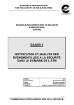
Figure 9: Directory
Structure for the
Externally provided
Ephemeris Files
The user must select a source for the satellite position
information. The ephemeris data is contained in standard RINEX
navigation files for the GPS. For the ESTB GEO, a format only
slightly different from the GLONASS RINEX navigation files has
been defined in the Interface Control Document (see [1]). The
user has the option of either selecting externally supplied RINEX
data files or selecting user data RINEX ephemeris files. This can
be done by checking the appropriate box External or User Data.
If the User Data ephemeris option is checked, then the Ephemeris Source field will
display the name base including directory structure for the ephemeris files. The
ephemeris files are assumed to follow the naming convention provided in the Interface
Control Document (see [1]).
Project:
PEGASUS
EUROCONTROL
Doc. No.:
Issue:
Software User Manual – WinGPSALL
Sheet
PEG-SUM-WGP
K
Date:
14/01/2004
21 of 37
If the External ephemeris option is checked, then the Ephemeris Source field will
display a path in which the externally supplied ephemeris data is assumed to exist. The
directory structure and the naming convention for the externally supplied ephemeris
data is contained in [20]. The user can change the file path by pressing the “…” button
next to the Ephemeris Source field.
It should be noted that if the option External Ephemeris is specified, the naming of the
ephemeris file and the existing directory structure must follow a particular convention. The
ephemeris file shall be named “BRDCddd0.yyN” with “ddd” being the julian day of the year
and “yy” being the year. The directory structure must be specified to a base directory, where
the individual ephemeris files themselves are contained in a subdirectory “YYYY” with
“YYYY” being the year. The appropriate directory structure is shown in figure 9 and
described in the relevant documentation ([20]).
3.4.3
User Receiver Options
The User Station options and the Reference Station options are shown in the next figure 10.
The Reference Station options will only be enabled, if the local area differential GNSS mode
is selected (see chapter 3.4.1).
When the box Use Initial WGS84 Position is checked, the user is able to provide the
position of the antenna in a static measurement set-up or the starting point of a dynamic
measurement set-up. This position then will be used in the determination of the deviations in
east-, north- and up-directions (see chapter 3.4.5).
This initial position must be given in WGS84 co-ordinates, i.e. latitude and longitude in
degrees and altitude as Height above ellipsoid (not above MSL). If no initial position is
specified by the user, the first receiver-computed position will be used to initialise the
process and to determine the position errors. This position will be displayed in the
appropriate field.
The receiver can be selected using the drop-down list Receiver. In WinGPSALL, the
following receiver types can be used.
<Automatic>: The receiver type will be automatically detected looking in the convertor
.mif file. Only the NovAtel™ OEM-3, DSNP™ Aquarius 5000 series, Septentrio PolaRx
and NovAtel OEM-4 receiver types can be detected.
NovAtel™ OEM-3: GPS standalone mode, GPS local area mode, SBAS NPA mode,
SBAS PA mode and GBAS PA mode.
DSNP™ Aquarius 5000 series: GPS standalone mode, GPS local area mode, SBAS
NPA mode SBAS PA mode and GBAS PA mode.
Septentrio PolaRx: GPS standalone mode, GPS local area mode, SBAS NPA mode,
SBAS PA mode and GBAS PA mode.
NovAtel OEM-4: GPS standalone mode, GPS local area mode, SBAS NPA mode
SBAS PA mode and GBAS PA mode.
Project:
PEGASUS
EUROCONTROL
Doc. No.:
Issue:
Software User Manual – WinGPSALL
Sheet
PEG-SUM-WGP
K
Date:
14/01/2004
22 of 37
Litton 8 channel: GPS standalone mode, GPS local area mode (implemented in
SAPPHIRE phases 1 and 2)
Honeywell 16 channel: GPS standalone mode, GPS local area mode (implemented in
SAPPHIRE phases 1 and 2)
D920 12 channel: GPS standalone mode, GPS local area mode (implemented in
SAPPHIRE phases 1 and 2)
If the GNSS mode is set to SBAS NPA mode or SBAS PA and a receiver type other than
the NovAtel™ OEM3/OEM4, DSNP Aquarius™ or Septentrio™ receivers are selected, then
the Start button will not be enabled until the user selects the appropriate mode or
appropriate receiver.
Figure 10: Screenshot of the User and Reference Station Options
The information for the field Data Rate must be provided by the user, since the nominal
update rate of the range measurement data will be used to check the consistency of the
data internally. It is recommended that the receiver set-up described in the Interface Control
Document ICD [1] is used, where the data rate it set to 1 Hz as a default value. However, if
other data rates are used, the user must provide the appropriate value in the field Data
Rate.
The checkbox UTC/GPS Time Transformation is provided for consistency and
compatibility reasons only. The receivers implemented in SAPPHIRE phases I and II use a
time synchronisation scheme which is based on UTC time, whereas the receivers
implemented in the PEGASUS development will use a time synchronisation scheme which
is based on the receiver delivered GPS time. Thus, this box will only be enabled when an
appropriate receiver is selected. For more information, please refer to the relevant
documentation ([20]).
If the GPS local area mode is selected, then the operator must specify an initial position for
the antenna of the reference station in order for the program to be able to start. Additionally,
if no initial position for the user receiver is provided in the local area differential mode, then
Project:
PEGASUS
EUROCONTROL
Doc. No.:
Issue:
Software User Manual – WinGPSALL
Sheet
PEG-SUM-WGP
K
Date:
14/01/2004
23 of 37
the position of the reference station will be as well used for the user receiver (i.e. to start the
positioning and to compute the errors / flight track).
3.4.4
Satellite Selection Options
The satellite selection options are displayed in the following figure 11. Individual satellites
can be selected / de-selected for the use in the position computation before the start of a
particular data evaluation.
The checkboxes are organised by the PRN number
of the satellites. If a satellite is to be used in the
position solution, the box for the appropriate PRN
number must be checked. Conversely, if a satellite
is to be masked and not used in the position
solution, the appropriate box must be unchecked.
The SBAS PRN numbers will be enabled (and thus
can be checked and unchecked), if the range option
SBAS (see chapter 3.4.1) is checked. The
GLONASS PRN numbers are disabled for the
WinGPSALL, since this option will not be available
until further notice.
Figure 11: Screenshot of the
Satellite Selection Option
3.4.5
After the Start button has been pressed and a
position computation run is launched, the Satellite
Selection options will be disabled. Thus, the user is
not able to select / de-select satellites during a run.
Instead, the Satellite Selection option will be used to
display the status of each individual satellite during
a position computation run (chapter 3.4.5).
Display of Progress
The progress for the WinGPSALL program will be displayed by two indications. As one
means, there is the progress bar, as shown in the following figure 12. It also includes a
numerical presentation of the progress.
Figure 12: Screenshot of the Progress Bar
Additionally, the current achieved position solution will be shown in the graphical display
(see figure 13). If an initial WGPS position is provided by the user (see chapter 3.4.3), then
this position will be used to determine the difference in north-, east- and up-direction.
Project:
PEGASUS
EUROCONTROL
Doc. No.:
Issue:
Software User Manual – WinGPSALL
Sheet
PEG-SUM-WGP
K
Date:
14/01/2004
24 of 37
If an initial position is not supplied (only possible
in standalone mode, basic wide area mode and
precise wide area mode, see section 3.4.3), then
the first position solution of the receiver will be
used to determine the difference of the further
computed positions.
Figure 13: Screenshot of the
Position Deviation
The current position deviation will be shown
using a black cross, whereas the history of the
position solution is displayed using red crosses.
Thus, if a static measurement set-up had been
used to collect the data and the real position of
the antenna is provided, then the display will
show the current error in the position estimation.
If a dynamic measurement set-up had been
used to collect the data and the starting point of
the measurement activities is provided, then the
display will show the covered distance during the
measurement.
The deviations in east- and north-direction are displayed additionally as numeric values in
the field below the graphical display (see figure 14). Furthermore, the date and time of the
evaluated data is displayed.
Additionally, the user will find a "traffic light"
display of the horizontal and vertical protection
level situation. The following colours are used:
Figure 14: Screenshot of the
Position Deviation Display
grey: HPL / VPL can not be determined
red: HPL / VPL are above the relevant
alarm limit
green: HPL / VPL are below the relevant
alarm limit
In order to determine the relevant alarm limits, for the SBAS NPA mode (see chapter
3.4.1), the flight phase “Non Precision Approach” is assumed, whereas for the SBAS PA
(see chapter 3.4.1), the flight phase “CAT I” is assumed.
The scale of the graphical window is equal in both directions and can be selected from the
following range :
± 5 m, ± 10 m, ± 50 m, ±100 m, ± 500 m,
± 1 km, ± 5 km, ± 10 km, ± 50 km, ± 100 km, ± 500 km
by using the drop-down list Scale. If the determined position deviations are greater in
magnitude than the scaling would allow them to be displayed, a cross on the frame of the
window is drawn in the direction of the position deviation (i.e. a clipping is implemented).
The scaling can be changed during one data evaluation run. If the user changes the scaling
Project:
PEGASUS
EUROCONTROL
PEG-SUM-WGP
Doc. No.:
Issue:
Software User Manual – WinGPSALL
K
Date:
14/01/2004
25 of 37
Sheet
during one run, the last thousand position solutions (i.e. the deviations in north- and eastdirection) will be redrawn.
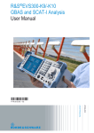
During a particular position computation run, the status of each individual satellite is
displayed using a colour-coding scheme (see figure 15). A legend for the colour-coding is as
well included in the program (see figure 16).
grey: satellite is de-selected
black: satellite is selected
blue: raw data from satellite is available,
however, there are no ephemeris data for that
satellite
yellow: raw data and ephemeris data are
available, however, the satellite is flagged as
unusable due to range data inconsistency
red: satellite is flagged as unusable by
either GPS or SBAS
green:
computation
satellite
is
used
for
position
Figure 15: Screenshot of the
Satellite Status Display
Figure 16: Screenshot of the Satellite Status Legend
3.5 Data Output
The output of the WinGPSALL program consists of several files in which the relevant data is
provided.
A configuration file ( "*.wif" ) is written to the data directory specified, which contains the
user-specified options. In particular, the used initial position / reference position is contained
in that log-file.
There are two output files. These data file can be written with or without a header (see
chapter 3.4.1). The delimiter that has been used by the CONVERTOR program will be
recognised automatically by WinGPSALL. This delimiter will as well be used for the writing
of the output file.
Project:
PEGASUS
EUROCONTROL
Doc. No.:
Issue:
Software User Manual – WinGPSALL
Sheet
PEG-SUM-WGP
K
Date:
14/01/2004
26 of 37
The PEGASUS output file (chapter 3.4.1) will contain PEGASUS-relevant information,
i.e. position- and time-solution, protection levels and position errors. A detailed
description of the file format can be found in appendix A.1
The SAPPHIRE output file (chapter 3.4.1) will contain the original SAPPHIRE-relevant
information, i.e. position-, velocity- and time-solution and range-related information for
every satellite. A detailed description of the file format can be found in appendix A.2
If the input file for the conversion has been recorded on the 30th October 2000 and named
EGNOS.BIN, the output files generated by the CONVERTOR are described in the in the
Software User Manual for the PEGASUS Module CONVERTOR in the relevant chapter.
Using these files as an input for WinGPSALL, the following output files of the position
computation process will be created:
EGNOS.WIF:
the log-file for the position computation process
EGNOS.CSV:
the PEGASUS-related output file
EGNOS_S.CSV:
the SAPPHIRE-related output file
Project:
PEGASUS
EUROCONTROL
Doc. No.:
Issue:
Software User Manual – WinGPSALL
Sheet
PEG-SUM-WGP
K
Date:
14/01/2004
27 of 37
Appendix A: Output Format of WinGPSALL
The output of the WinGPSALL program consists of two files in which the relevant data is
provided. The format of the output file is based on the existing output file format for
SAPPHIRE (in particular, the format specified in [20], but is extended to contain additional
information.
Appendix A.1 PEGASUS Output
The description of the complete format for the PEGASUS-related output file can be found in
the following table.
Number
Parameter
Units
Format
Note
1
Sample
N/A
integer
sample number in the file
2
ACUTC_year
year
integer
year of data set in UTC time
3
ACUTC_month
month
integer
month of data set in UTC time
4
ACUTC_day
day
integer
day of data set in UTC time
5
ACUTC_hrs
hrs
integer
hour of data set in UTC time
6
ACUTC_mins
min
integer
minute of data set in UTC time
7
ACUTC_secs
s
integer
second of data set in UTC time
8
VALID_POS
N/A
integer
GPS standalone mode:
0: range measurements, but invalid position
1: range measurements, valid position
GPS local area differential mode :
0: range measurements, but invalid position
1: range measurements, valid position
2: gap in reference data, invalid position
3: gap in user data, invalid position
SBAS Non-Precision Approach mode:
0: range measurements, but invalid position
1: range measurements, valid position
SBAS Precision Approach mode:
0: range measurements, but invalid position
1: range measurements, valid position
9
GPS_WN
N/A
integer
week number GPS time
10
GPS-T
s
float
seconds GPS time of measurement (uncorrected for receiver clock
errors)
11
GPS-LAT
1°
float
latitude computed position (WGS84)
12
GPS-LON
1°
float
longitude computed position (WGS84)
13
GPS-ALT
m
float
altitude computed position (WGS84)
14
GPS-H
m
float
altitude computed position (mean sea level)
15
NSV
N/A
float
number of satellites used for position computation
16
D-NORTH
m
float
north/south deviation of computed position
17
D-EAST
m
float
east/west deviation of computed position
18
D-UP
m
float
up/down deviation of computed position
19
D-HOR
m
float
horizontal deviation of computed position
20
D-POS
m
float
deviation of computed position
Project:
PEGASUS
21
VALID-XPL
EUROCONTROL
Doc. No.:
Issue:
Software User Manual – WinGPSALL
N/A
integer
Sheet
PEG-SUM-WGP
K
Date:
14/01/2004
28 of 37
GPS standalone mode, GPS local area differential mode
0: no valid position
1: valid position
SBAS Non-Precision Approach mode, SBAS Precision Approach mode:
0: XPL can not be computed
1: XPL computed
22
XPL-TYPE
N/A
integer
0: no
1: protection levels, MT 10, SBAS ionospheric corrections
2: protection levels, MT 10, standard ionospheric corrections
3: protection levels, no MT 10, standard ionospheric corrections
23
HPL
m
float
horizontal protection level
24
HAL
m
float
horizontal alarm limit
25
VPL
m
float
vertical protection level
26
VAL
m
float
vertical alarm limit
for each tracked satellite for 24 channels
27
GPS-SVN
N/A
integer
PRN number of satellite
Table A.1: Output Format of WinGPSALL
Appendix A.2 SAPPHIRE Output
The description of the complete format for the SAPPHIRE-related output file can be found in
the following table.
Number
Parameter
Units
Format
Note
1
Sample
N/A
integer
sample number in the file
2
ACUTC_year
year
integer
year of data set in UTC time
3
ACUTC_month
month
integer
month of data set in UTC time
4
ACUTC_day
day
integer
day of data set in UTC time
5
ACUTC_hrs
hrs
integer
hour of data set in UTC time
6
ACUTC_mins
min
integer
Minute of data set in UTC time
7
ACUTC_secs
s
integer
Second of data set in UTC time
8
GPS_t
s
float
GNSS seconds in week (uncorrected for receiver clock errors)
float
Receiver clock error
9
GPS_ClkErr
ss
-1
-2
10
GPS_CkErrDr
ss
float
receiver clock drift
11
GPS_Lat
1°
float
latitude computed position (WGS84)
12
GPS_Lon
1°
float
longitude computed position (WGS84)
13
GPS_Alt
ft
14
15
GPS_VNS
GPS_VEW
float
altitude computed position (mean sea level)
ms
-1
float
north/south computed velocity
ms
-1
float
east/west computed velocity
-1
float
up/down computed velocity
16
GPS_Vup
ms
17
GPS_GDOP
N/A
float
GDOP
18
GPS_PDOP
N/A
float
PDOP
19
GPS_HDOP
N/A
float
HDOP
20
GPS_VDOP
N/A
float
VDOP
21
GPS_TDOP
N/A
float
TDOP
EUROCONTROL
Project:
PEGASUS
Doc. No.:
K
Issue:
Software User Manual – WinGPSALL
PEG-SUM-WGP
Date:
14/01/2004
29 of 37
Sheet
Number
Parameter
Units
Format
Note
22
GPS_SATV
N/A
integer
number of satellites visible to the receiver
23
GPS_SATT
N/A
integer
number of satellites tracked by the receiver
for each tracked satellite for 24 channels
24
GPS_SVN
N/A
integer
25
GPS_STAT
N/A
integer
PRN number of satellite
status of satellite tracking
0
1
2
3
4
5
6
7
8
9
10
11
12
13
no raw data
raw data
no last raw data
no last doppler
raw data check ok
raw data check not ok
low elevation
masked by extern
no ephemeris
ephemeris too old
used for pos
no differential corrections
flagged by SBAS
range step detected
satellite not used
satellite not used
satellite not used
satellite not used
satellite not used
satellite not used
satellite not used
satellite not used
satellite not used
satellite not used
26
GPS_PRres
m
float
pseudorange residuum
27
GPS_SVX
m
float
satellite position x (WGS84)
28
GPS_SVY
m
float
satellite position y (WGS84)
29
GPS_SVZ
m
float
satellite position z (WGS84)
30
GPS_R
m
float
Pseudorange
31
GPS_AZIM
1°
float
azimuth of satellite
32
GPS_ELEV
1°
float
elevation of satellite
33
dHDOP
N/A
float
Delta HDOP – availability indicator for receiver autonomous integrity
monitoring
34
dVDOP
N/A
float
Delta VDOP – availability indicator for receiver autonomous integrity
monitoring
35
RCxgeo
N/A
float
element x of design matrix
36
RCygeo
N/A
float
element y of design matrix
37
RCzgeo
N/A
float
element z of design matrix
Table A.2: Output Format of WinGPSALL SAPPHIRE
Project:
PEGASUS
EUROCONTROL
Doc. No.:
Issue:
Software User Manual – WinGPSALL
Sheet
PEG-SUM-WGP
K
Date:
14/01/2004
30 of 37
Appendix B: Errors, Warnings and Recovery Procedures
This appendix contains a list of errors and warning that are generated by the programs of
the PEGASUS module WinGPSALL. Additionally, for each error message and warning, a
possible cause is given and an appropriate recovery procedure is proposed.
In this context, errors are considered to be fault conditions that do not allow the associated
program to run and to produce an output file. Warnings are considered to be fault conditions
that allow an associated program to run, however, due to the fault condition, the result
output file may be incomplete or less useful.
In contrast to that, user notifications are considered to be conditions where the user has
selected an option which may seem to be inappropriate for the associated program. The
user is presented at the time of the execution with a notification of the condition and the
program proposes a suitable procedure to change the selected option. These user
notifications are not included in this appendix.
Error Message: Could not find options file
Cause: The INI-file could not be found, since it was not in the specified directory. If no INIfile was specified at the start, the program assumes the file “WinGPSALL.INI” to be present
in the directory where the executable is located. Either the file was not found or the user had
no reading access rights to open the file. The user should ascertain that the specified input
file does exist. Additionally, it may be necessary to check (in co-ordination with the system
administrator, if needed) that the user has the necessary rights to access the file.
Recovery: In the interactive mode, the user interface will appear filled with blanks and
default values (where appropriate). The operator can fill in the particular fields and start the
program. In the background mode, a log file “WinGPSALL.ERR” will be created which
contains the appropriate message.
Warning Message: Wrong Parameter Setting
Cause: The INI-file contains at least for one parameter erroneous settings. The appropriate
values for each parameter are specified in the appendix C of this document..
Recovery: In the interactive mode, the user interface will appear filled with default settings
for that particular parameter and the operator can fill in the particular fields and start the
program. In the background mode, a log file will be created which contains the appropriate
message. The name of the log file will be determined by the name of the input file (if
provided) or will be the standard “WinGPSALL.ERR”.
Project:
PEGASUS
EUROCONTROL
Doc. No.:
Issue:
Software User Manual – WinGPSALL
Sheet
PEG-SUM-WGP
K
Date:
14/01/2004
31 of 37
Warning Message: Sorry. Could not open file for MT … . Exiting now the process.
Cause: The ESTB message type data file specified could not be opened. Either the file was
not found or the user had no reading access rights to open the file. The program stops the
execution.
Recovery: The user should ascertain that the specified input file does exist. Additionally, it
may be necessary to check (in co-ordination with the system administrator, if needed) that
the user has the necessary rights to access the file.
Warning Message: Sorry. Could not open navigation input file.
Cause: The GNSS range- and position data file could not be opened. Either the file was not
found or the user had no reading access rights to open the file.
Recovery: The user should ascertain that the specified input file does exist. Additionally, it
may be necessary to check (in co-ordination with the system administrator, if needed) that
the user has the necessary rights to access the file. In the interactive mode, the user
interface will appear and the operator can specify an appropriate input file. In the
background mode, the program will create the log file “WinGPSALL.ERR” which contains
the appropriate error message and will terminate.
Warning Message: Sorry. Could not open reference input file.
Cause: The GNSS range- and position data file could not be opened. Either the file was not
found or the user had no reading access rights to open the file.
Recovery: The user should ascertain that the specified input file does exist. Additionally, it
may be necessary to check (in co-ordination with the system administrator, if needed) that
the user has the necessary rights to access the file. In the interactive mode, the user
interface will appear and the operator can specify an appropriate input file. In the
background mode, the program will create the log file which contains the appropriate error
message and will terminate. The name of the log file will be determined either by the name
of the input file (if provided) or will be “WinGPSALL.ERR”.
Warning Message: Sorry. Could not open output file for PEGASUS.
Cause: The output file for PEGASUS could not be opened. Either the file was not found or
the user had no writing access rights to open the file.
Recovery: The user should ascertain that the specified input file does exist. Additionally, it
may be necessary to check (in co-ordination with the system administrator, if needed) that
the user has the necessary rights to access the file. In the interactive mode, the user
interface will appear and the operator can specify an appropriate input file. In the
background mode, the program will create the log file which contains the appropriate error
message and will terminate. The name of the log file will be determined either by the name
of the input file (if provided) or will be “WinGPSALL.ERR”.
Project:
PEGASUS
EUROCONTROL
Doc. No.:
Issue:
Software User Manual – WinGPSALL
Sheet
PEG-SUM-WGP
K
Date:
14/01/2004
32 of 37
Warning Message: Sorry. Could not open output file for SAPPHIRE.
Cause: The output file for SAPPHIRE could not be opened. Either the file was not found or
the user had no writing access rights to open the file.
Recovery: The user should ascertain that the specified input file does exist. Additionally, it
may be necessary to check (in co-ordination with the system administrator, if needed) that
the user has the necessary rights to access the file. In the interactive mode, the user
interface will appear and the operator can specify an appropriate input file. In the
background mode, the program will create the log file which contains the appropriate error
message and will terminate. The name of the log file will be determined either by the name
of the input file (if provided) or will be “WinGPSALL.ERR”.
Warning Message: Parameters not found ……. The program will not start.
Cause: WinGPSALL performs a name check on the parameters contained in one file. For
the evaluation of the positioning and integrity information, certain parameters are of
essential importance. If these parameters are not found, then the program stops the
execution.
Recovery: The user should ascertain whether the specified file contains a header (i.e. the
CONVERTOR program must be run with the option of creating a header). If the ESTB data
file was not created by the CONVERTOR program, the user should ascertain additionally, if
the parameter name is provided correctly (the relevant information on the parameter names
can be found in the ICD ([1])
Warning Message: Delimiter not found.
Cause: A delimiter character for the parameter fields could not be determined in the input
file. The program stops the execution.
Recovery: The user should ascertain that the parameters and values in the input files are
delimited by a correct field delimiter (specified in the ICD([1])). It is of importance to notice
that the GNSS range- and position data file determines the delimiter character used in all
other input files. Thus, the ESTB data files or the reference station input data file must
contain the identical delimiter.
Warning Message: No fields were found, but the end of line was reached. Maybe the … is
a wrong field separator. Terminating.
Cause: A delimiter character for the parameter fields could not be determined in the input
file. The program stops the execution.
Recovery: The user should ascertain that the parameters and values in the input files are
delimited by a correct field delimiter (specified in the ICD ([1])). It is of importance to notice
that the GNSS range- and position data file determines the delimiter character used in all
other input files. Thus, the ESTB data files or the reference station input data file must
contain the identical delimiter.
Project:
PEGASUS
EUROCONTROL
Doc. No.:
Issue:
Software User Manual – WinGPSALL
Sheet
PEG-SUM-WGP
K
Date:
14/01/2004
33 of 37
Appendix C: Format and Description of the INI-Files
The user options and settings for the WinGPSALL program will be kept in corresponding
initialisation files. They will be saved on program exit so that they will be available on the
next start. The files may, however, also be edited manually or generated externally, e.g. by
the PEGASUS frame (for more information, the interested reader is referred to [3]).
Therefore, the following sections describe the initialisation file contents and shows a sample
file.
The WinGPSALL default initialisation file is named “WinGPSALL.INI” and located in the
WinGPSALL working directory. A different file may be specified though as described in
chapter 3.
Appendix C.1 File Contents
The description of the complete format for the WinGPSALL initialisation file can be found in
the following table. Any parameter that is not specified takes its default value, as is the case
when no initialisation file can be found at all.
Key name
Description
Type Limits & Specifications Default
[System] section
Outputfile
name of the output file
string
max. 255 characters
(empty)
GNSS GPS
flag whether GPS ranging is to be
used
int
0 = no, 1 = yes
1 = yes
GNSS GLONASS
flag whether GLONASS ranging is to
be used
int
0 = no, 1 = yes
0 = no
GNSS ESTB
flag whether ESTB ranging is to be
used
int
0 = no, 1 = yes
0 = no
Write Header
flag whether header for output files
is to be generated
int
0 = no, 1 = yes
1 = yes
Output Pegasus
flag whether the PEGASUS output file int
is to be generated
0 = no, 1 = yes
1 = yes
Output Sapphire
flag whether the SAPPHIRE output
file is to be generated
int
0 = no, 1 = yes
0 = no
Differential GPS
DGPS mode
int
0 = GPS standalone,
1 = GPS local area,
2 = SBAS NPA,
3 = SBAS PA,
4 = GBAS PA
5 = GPS (using SBAS satellites)
6 = GPS (using GBAS satellites)
0 = standalone
Smoothing Time
time constant [s] for range smoothing
int
0 ≤ Smoothing Time ≤ 100;
0 implying no smoothing
0 [s] = no smoothing
Max DataGap
maximum allowable interruption in the int
data stream before the carrier
smoothing range filter will be reinitialised for a satellite
0 ≤ Max DataGap ≤ 10
3
Weighted Pos
flag whether weighted position
solution is to be used
0 = no, 1 = yes
0 = no
int
Project:
PEGASUS
EUROCONTROL
PEG-SUM-WGP
Doc. No.:
Issue:
Software User Manual – WinGPSALL
K
Date:
14/01/2004
34 of 37
Sheet
Key name
Description
Type Limits & Specifications Default
Decoding of Ephemeris
flag whether ephemeris is read in
from receiver generated files or from
externally supplied files
int
0 = no, 1 = yes
0 = no
Directory Name
name of directory where ephemeris
data can be found
string
max. 255 characters
(empty)
Min. Elevation
Minimum satellite elevation [°] to be
considered in the positioning
float
0.0 ≤ Min. Elevation ≤ 90.0
0.0 [°]
Iono Correction
Ionospheric correction model
int
0 = none,
1 = standard GPS corrections,
2 = RTCA Do 229A corrections
0 = none
Tropo Correction
Tropospheric correction model
int
0 = none,
1 = standard GPS corrections,
2 = RTCA Do 229B corrections
0 = none
ScaleGraph
Scaling factor for the position solution
display window
int
0 = 5 m, 1 = 10 m, 2, = 50 m,
3 = 100 m, 4 = 500 m, 5 = 1km,
6 = 5 km, 7 = 10 km, 8 = 50 km,
9 = 100 km, 10 = 500 km
3 = 100 m
[User Station] section
Filename
name of navigation input file
string
max. 255 characters
(empty)
Initial Pos
flag whether provided initial position
is to be used (otherwise first position
solution will be taken)
int
0 = no, 1 = yes
1 = yes
Latitude
user station initial latitude [°]
float
-90.0 ≤ Latitude
Longitude (°)
user station initial longitude [°]
float
-180.0 ≤ Longitude (°)
≤ 180.0
0.0 [°]
Ellip. H
user station initial elliptic height [m]
above geoid (not above MSL !)
float
-457.2 ≤ Ellip. H
≤ 39950.7456
0.0 [°]
Receiver type
Definition of user station receiver
type
int
0 = unknown
1 = Litton 8 channel
2 = Honeywell 16 channel
3 = D920 12 channel
4 = DNSP Aquarius 5000,
5 = NovAtel WAAS/Millennium,
6 = Septentrio PolaRx,
7 = NovAtel OEM4
0 = unknown
Data Rate [Hz]
data rate for user receiver ranging
data [Hz]
float
0.0 < Data Rate [Hz]
1.0 [Hz]
UTC/GPS Time
Correction
flag whether user station UTC to
GPS time transformation is to be
enabled
int
0 = no, 1 = yes; NOTE: this
value will always be set to 0 for
Receiver types 4, 5, or 6
1 = yes for
Receiver type
0, 1, 2, or 3;
0 = no otherwise
(°)
(m)
(°) ≤ 90.0
(m)
0.0 [°]
[Reference Station] section
Filename
Latitude
(°)
Longitude (°)
name of reference station input file
string
max. 255 characters
(empty)
reference station initial latitude [°]
float
-90.0 ≤ Latitude
reference station initial longitude [°]
float
-180.0 ≤ Longitude (°)
≤ 180.0
(°) ≤ 90.0
0.0 [°]
0.0 [°]
Project:
PEGASUS
EUROCONTROL
PEG-SUM-WGP
Doc. No.:
Issue:
Software User Manual – WinGPSALL
K
Date:
14/01/2004
35 of 37
Sheet
Key name
Description
Type Limits & Specifications Default
Ellip. H
reference station initial elliptic height
[m] above geoid (not above MSL !)
float
-457.2 ≤ Ellip. H
≤ 39950.7456
Receiver type
definition of reference station
receiver type
int
0 = unknown
1 = Litton 8 channel
2 = Honeywell 16 channel
3 = D920 12 channel
4 = DNSP Aquarius 5000,
5 = NovAtel Millennium,
6 = Septentrio PolaRx,
7 = NovAtel OEM4
0 = unknown
Data Rate [Hz]
data rate for reference receiver
ranging data [Hz]
float
0.0 < Data Rate [Hz]
1.0
UTC/GPS Time
Correction
flag whether reference station UTC
to GPS time transformation is to be
enabled
int
0 = no, 1 = yes;
1 = yes for
Receiver type
0, 1, 2, or 3;
(m)
(m)
NOTE: this value will always be
set to 0 for Receiver types 4,
5, 6 or 7
0.0 [°]
0 = no otherwise
[Satellite Selection] section
Select SV
1(#)
...(#)
flag whether GPS SV # 1 is to be
used for the positioning process
int
0 = no, 1 = yes
1 = yes
…
…
…
…
Select SV
32(#)
flag whether GPS SV # 32 is to be
used for the positioning process
int
0 = no, 1 = yes
1 = yes
Select SV
38(#)
flag whether GLONASS SV # 38 is to
be used for the positioning process
int
0 = no, 1 = yes
1 = yes
…
…
…
…
61(#)
flag whether GLONASS SV # 62 is to
be used for the positioning process
int
0 = no, 1 = yes
1 = yes
Select SV 120(#)
flag whether ESTB SV # 120 is to be
used for the positioning process
int
0 = no, 1 = yes
1 = yes
...(#)
…
…
…
…
Select SV 138(#)
flag whether ESTB SV # 120 is to be
used for the positioning process
int
0 = no, 1 = yes
1 = yes
...(#)
Select SV
Appendix C.2 Sample File
[System]
Output Filename=j:\pplus\data\esa_20021125_0810_N4.csv
GNSS GPS=1
GNSS GLONASS=0
GNSS ESTB=0
Differential GPS=1
Smoothing Time=5
Max DataGap=3
Weighted Pos=0
Write Header=1
(#) SV number must have a field width of 3 characters with right aligned numbers ("%3i" format specifier in C++).
Project:
PEGASUS
EUROCONTROL
Doc. No.:
Issue:
Software User Manual – WinGPSALL
Sheet
Output Pegasus=1
Output Sapphire=0
Decoding of Ephemeris=0
Directory Name=j:\pplus\data\esa_20021125_0810_N4
Min. Elevation=15.0
Iono Correction=1
Tropo Correction=1
ScaleGraph=8
[User Station]
Filename=j:\pplus\data\esa_20021125_0810_N4.1Hz
Initial Pos=1
Latitude (°)=52.3458326
Longitude (°)=10.5765667
Ellip. H (m)=145.4354
Receiver type=4
Data Rate [Hz]=1.000
UTC/GPS Time Correction=0
[Reference Station]
Filename=j:\pplus\data\esa_20021125_0810_N4_ref.1Hz
Initial Pos=1
Latitude (°)=52.31767337
Longitude (°)=10.55311378
Ellip. H (m)=203.4578
Data Rate [Hz]=1.000
Receiver type=0
UTC/GPS Time Correction=0
[Satellite Selection]
Select SV
1=1
Select SV
2=1
(… keys for SVs 3 to 30 deleted here)
Select SV 31=1
Select SV 32=1
Select SV 38=1
Select SV 39=1
(… keys for SVs 40 to 59 deleted here)
Select SV 60=1
Select SV 61=1
Select SV 120=0
Select SV 121=0
(… keys for SVs 122 to 136 deleted here)
Select SV 137=0
Select SV 138=0
PEG-SUM-WGP
K
Date:
36 of 37
14/01/2004
Project:
PEGASUS
EUROCONTROL
Doc. No.:
Issue:
Software User Manual – WinGPSALL
END OF DOCUMENT
Sheet
PEG-SUM-WGP
K
Date:
37 of 37
14/01/2004