1
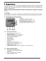
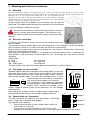
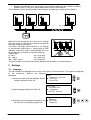
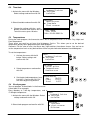
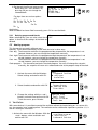
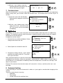
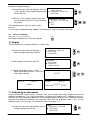
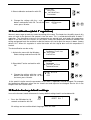
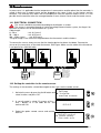
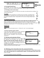
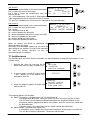
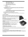
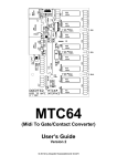
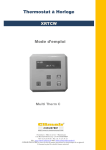
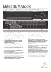
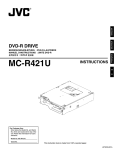
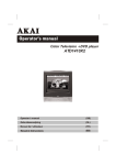
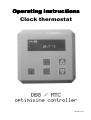
Operating instructions
Clock thermostat
DB8 / MTC
optimising controller
MTC-GB v02-02
1 Table of contents
OPERATING INSTRUCTIONS
INSTRUCTIONS
1
CLOCK THERMOSTAT 1
1
TABLE OF CONTENTS 2
2
DESIGNATED USE
2.1 SAFETY
3
3
3
DESCRIPTION OF THE THERMOSTAT
3
3.1 CONCISE SPECIFICATIONS 3
3.2 TECHNICAL SPECIFICATIONS 3
4
MOUNTING AND ELECTRICAL CONNECTION
4.1
4.2
4.3
4.4
5
MOUNTING 4
ELECTRICAL CONNECTION 4
ONE HEATER ON ONE CONTROLLER
SEVERAL UNITS ON 1 THERMOSTAT
4
4
4
SETTINGS 5
5.1 LANGUAGE 5
5.2 TIME/DATE 6
5.3 TEMPERATURES
6
5.4 CLOCK PROGRAM
6
5.4.1 Deleting programmed blocks
5.5 HEATING PROGRAM 7
6
VENTILATION
7
OVERTIME TIMER
8
OPTIMISER
9
KEYBOARD LOCKING 8
7
7
8
8
9.1 UNLOCK THE DISPLAY
9
10
DISPLAY
11
CALIBRATING THE THERMOSTAT 9
12
DESTRATIFICATION (DELAT T REGULATION) 10
13
BACK TO FACTORY DEFAULT SETTINGS
14
REMOTE SENSOR
14.1
14.2
14.3
14.4
14.5
9
10
11
ELECTRICAL CONNECTION: 11
SETTING THE CONTROLLER FOR THE REMOTE SENSOR
AVERAGE TEMPERATURES
12
SETTING UP THE REMOTE SENSOR 12
ERRORS WITH THE REMOTE SENSOR 12
11
15
SOLVING AND ANALYSING FAILURES
16
OBTAINING EXTRA INFORMATION FROM THE CONNECTED HEATERS 12
17
INSTALLER MENU
13
18
INTERNAL BATTERY
14
19
MAINTENANCE AND SERVICE
19.1.1 Waste processing
Room thermostat DB8 / MTC
12
14
14
2/14
2 Designated use
The Multi Therm-C clock thermostat has been designed to control room heaters that work according
to the Argus bus system. This is a two-wire low voltage communication system. The thermostat is not
suitable to switch 24V, 230V or other signals. It may only be used in dry rooms with slight impurities
(degree of protection IP30).
Before use, carefully read these operating instructions and observe them. In case the mounting and
operating instructions are not observed, the manufacturer’s warranty will not apply to any resulting
damage.
2.1
Safety
Electrical devices may only be connected by a qualified electrician. Always observe the relevant
national regulations. Interferences and changes to the device will lead to cancellation of the warranty.
3 Description of the thermostat
1
3
1. Display
2. Info button to display information
3. Menu button to enter and exit the menu
4. OK button to confirm a setting
5. + and – buttons to raise or lower settings
6. openings for the temperature sensor
5
2
3.1
4
5
6
Concise specifications
•
•
•
•
•
•
•
•
•
•
•
•
•
•
3.2
Room thermostat with clock function
Optimising controller
Permanent display of the room temperature
10 different programmable time blocks
Up to 8 heaters controllable
Frost protection
Keyboard locking
Overtime program
Ventilation
Failure diagnosis of the devices
Suppression of interference of the heater
Compensation for wall influence
suited for remote sensor
Supplied battery, excellent for preserving data in case of power failure
Technical specifications
•
•
•
•
•
Power supply: low-voltage current
Temperature range: 0-30 degrees Celsius
Controller: PI
Clock: 10 programmable switch blocks
Degree of protection: IP30
Room thermostat DB8 / MTC
3/14
4 Mounting and electrical connection
4.1
Mounting
The clock thermostat is suitable for mounting in dry, not too dusty rooms. Place the thermostat in a room in a location
where air can circulate unimpeded. Beware that in winter the low-standing sun cannot shine directly onto the thermostat.
Placement above or near a device that radiates heat is also not recommended. Avoid
placement on a cold outdoor wall; place the thermostat on an indoor wall free of draught.
All these things have an adverse effect on the correct measurement of the room temperature
and hence on the proper operation of the thermostat.
By pressing the notch on the bottom of the thermostat, you can open the
thermostat. The bottom plate containing the connector can be mounted on
a universal wall box or directly on the wall.
Be ware that the controller should not be mounted near a anennas
from any internal communication network. These antennas may
disturb the correct functioning of the controller. Always keep a few meters
distance.
4.2
Electrical connection
To connect the thermostat, always ensure that the heating device has
been shut down.
The thermostat receives electric power from the heating device. The connection is 2-wire low-voltage
and is not phase sensitive, i.e. it does not matter how the wires are connected.
Beware that the thermostat wires do not run through the same circuit as 230 volt wires and are not
parallel with high-voltage current wires.
If the wires are longer than 20 metres or run through an environment where there is a great deal of
EMC radiation, a low-noise cord is recommended. This can, for example, be a wire with an earthed
sheathing.
Cable length:
0 – 50 m
- min. 0,13 mm2
50 – 100 m
- min. 0,25 mm2
100 – 250 m (max.)
- min. 0,50 mm2
The given length is the maximum distance between the controller(s) and the heater(s).
One heater on one controller
Standard nothing needs to be changed in the heating device. In case the
thermostat does not work, check that the micro-switches S2 on the print
plate in the room heater are set as shown on the right: number 1 up (ON)
and the other numbers down. The switch S3 should be set to 1. In case
several devices are connected to 1 thermostat,
S2
S3
ON
refer to the relevant chapter in this manual.
0 1
This thermostat is only suitable for connection
1 2 3 4 5 6 7 8
to heating devices specifically intended for this
purpose. Never connect, for example, 24V or
another voltage of another system to the thermostat. This can damage
the thermostat.
After making the changes inside the heater always unplug and re
plug the power to the heater for the changes to become effective.
S2
Several units on 1 thermostat
Thermostat (bus)
22°C
1 2 3
ON
4.4
L (230V AC)
Installer
Neutal
4.3
4 5
S3
0
1
Heater 1
1 2 3 4 5 6 7 8
The room thermostat can control up to 8 room heaters. Connecting
ON
1
0
Heater 2
them is simple, but it should be done properly.
1 2 3 4 5 6 7 8
Pay attention to the following:
ON
1
0
• Each unit must be given its own number (to be set with the
Heater 3
1
2
3
4
5
6
7
8
micro-switch S2 in the unit).
• One unit must have the S2 number 1 set on ON (this unit
provides for the communication) and S3 to 1, al the other heaters should have S3 set to 0.
Room thermostat DB8 / MTC
4/14
Between the separate units, the numbers 4 must be connected with the numbers 4 and the
number 5 with 5. They must not be connected in a cross-wise manner.
The functionality of the thermostat does not change by connecting a number of room heaters.
•
2 3
Neutal
4
5
1
2 3
4
1
5
Neutal
1
5
L (230V AC)
4
Heater 8
L (230V AC)
3
Neutal
2
Heater 3
L (230V AC)
Neutal
1
Heater 2
L (230V AC)
Heater 1
2
3
4
5
Max. 8 Heaters
Communicatie bus:
2 draads; laagspanning
22°C
beware that the thermostat wires do not run through
the same circuit as 230 volt wires and are not parallel
with high-voltage current wires.
If the wires are longer than 20 metres or run through
an environment where there is a great deal of EMC
radiation, a low-noise cord is recommended. This can,
for example, be a wire with an earthed sheathing.
22°C
Cable length:
0 – 50 m
- min. 0,13 mm2
50 – 100 m
- min. 0,25 mm2
100 – 250 m (max.)
- min. 0,50 mm2
The given length is the maximum distance between the controller(s) and the heater(s).
1 2 3
4 5
1 2 3
4 5
L (230V AC)
Neutal
L (230V AC)
Heater 3
Neutal
L (230V AC)
Heater 2
Neutal
Heater 1
1 2 3
4 5
5 Settings
5.1
Language
You can change the language of the various menu items of the thermostat. To change the language
of the thermostat, observe the following
procedure.
menu
keyboard locking
1. Activate the menu with the M button. Select ► settings
settings and confirm with OK.
installer
2. Select language and confirm with OK.
settings
calibration
► language
DeltaT active
language
Deutsch
3. Select the correct language and confirm with ► English
OK. Exit the menu by pressing M twice.
Francais
Room thermostat DB8 / MTC
5/14
5.2
Time/date
menu
keyboard locking
► settings
installer
1. Activate the menu with the M button.
Select settings and confirm with OK.
Settings
Heating prog.
► time/date
Clock program
2. Select time/date and confirm with OK.
3. Change the settings with the + and –
buttons and each time confirm with OK. Time /date
To exit the menu, press M twice.
Time 14:34
Date 01-04-2006 Mo
5.3
Temperatures
During the clock program, the thermostat works with 3 temperature levels in a room: Day, Night and
Frost temperature.
These levels can each be set from 0 to 30 degrees Celsius. This allows you to set the desired
temperature quickly when programming the clock program.
Comment. For the sake of ease, the names day, night and frost have been chosen. You are free to
set the temperature levels at any desired time and on any desired value between 0 and 30 degrees.
To set the temperatures:
5.4
1. Activate the menu with the M
button. Select settings and
confirm with OK.
menu
keyboard locking
► settings
installer
2. Select temperatures and confirm
with OK.
Settings
DeltaT active
► temperatures
Heating prog
3. Set the desired temperatures from
0 to 30ºC. Confirm with OK. Exit
the menu by pressing M twice.
temperatures
day
20.5ºC
night
15.0ºC
frost
6.0ºC
Clock program
You can program 10 time blocks in the thermostat.
A time block is for example:
Every Monday at 7.00 day temperature; and at
17.00 night temperature.
menu
keyboard locking
1. Activate the menu with the M button. Select
► settings
settings and confirm with OK.
installer
2. Select clock program and confirm with OK.
Room thermostat DB8 / MTC
settings
time/date
► clock program
Optimiser
6/14
3. Go through the different programmed
blocks with the + and – buttons. By
pressing OK you can change the
selected block.
Program
Block 1
Mo Tu We Th Fr
07:00 day
17:00 night
For days there are various options:
off
Mo Tu We Th Fr Sa Su
Mo Tu We Thu Fr
Sa Su
Mo
Tu
And further...
When the block has been filled in correctly, press OK to save the block.
5.4.1 Deleting programmed blocks
Program
When selecting day, you can also select the off Off
option. In that case the settings of the block are
deleted.
5.5
Block 1
Heating program
This thermostat can work in different ways.
Naturally, it can work automatically on the clock, but also in other ways.
Cont. day The thermostat maintains the programmed day temperature; the temperature is not
lowered. However, you can change the temperature manually.
Cont. night The thermostat maintains the programmed night temperature; the temperature is not
raised. However, you can change the temperature manually.
Cont. frost The thermostat maintains the programmed frost temperature; the temperature is not
raised. However, you can change the temperature manually.
Clock program The thermostat maintains the clock program. You can still change the set point
manually, the set point will return to its automated value at the program step of the clock.
1. Activate the menu with the M button.
Select settings and confirm with OK.
2. Select time/date and confirm with OK.
3. Change the settings with the + and –
buttons and each time confirm with OK.
To exit the menu, press M twice.
menu
keyboard locking
► settings
installer
settings
temperatures
► heating prog
time/date
Heating prog
Cont. frost
►Clock program
Cont. day
6 Ventilation
With some devices it is possible to control the ventilator without the heater being on. In summer this
can, for example, have a cooling effect. The ventilator can be switched to 4 positions: position 1, 2, 3
and off. Setting the ventilation:
1. Activate the menu with the M button. With the menu
overtime program
+ and – buttons select ventilation and
► ventilation
confirm with OK.
keyboard locking
Room thermostat DB8 / MTC
7/14
2. With the + and – buttons select the
Ventilation
ventilator position and confirm with OK.
Exit the menu by pressing M.
Off 1 ►2
3
7 Overtime timer
When the thermostat is set on the clock and you would like temporarily to maintain the temperature
longer on day level, you can do so with the overtime timer. The overtime timer can be set per 15
minutes.
1. Activate the menu with the M button .
Select overtime program and confirm
with OK.
menu
installer
► overtime program
ventilation
2. With the + and – buttons enter a time in
steps from 15 min., and confirm with
OK. The time will start to count down
immediately.
Overtime
01:15
8 Optimiser
the controller can be set in such a way that it will start the heaters earlier by means of a optimising
program. The controller calcultes when the heaters should be started in order to reach the setpoint
temperature at the desired time.
De optimiser can be set by:T
menu
keyboard locking
► settings
1. Activate the menu with the M button. Select
installer
settings and confirm with OK.
2. Select Optimiser and confirm with OK.
3. Change the settings with the + and – buttons
and each time confirm with OK. To exit the
menu, press M twice.
settings
Clock program
► Optimiser
display
Optimiser
On
►Off
After setting the optimeser it will take several days for the controller to gathered the information
needded for the calulations. When the controller is confronted with sudden colder or warmer nights it
wll not take this in its calculations inmediately. When the temperatures are lower for a few days it will
adjust its calculations.
Remark: The maximum time that the heaters will start earlier is 3 hours, and the earlier start is not
overnight.
9 Keyboard locking
It may be handy to secure the thermostat in whole or in part against unauthorised changing of the
settings.
There are several levels of security:
• Unlocked.
• Fully locked.
• Limited, with only the overtime timer.
Room thermostat DB8 / MTC
8/14
Setting the keyboard locking:
1. Activate the menu with the M button. With the
+ and – buttons select keyboard locking and
confirm with OK.
2. With the + and – buttons select the desired
level and confirm with OK. Exit the menu by
pressing M.
menu
ventilation
► keyboard locking
settings
Keyboard locking
On excl. overtime
► On
Off
The locking becomes active as soon as OK is
pressed.
The message “keyboard locking” appears in the display as soon as a button is pressed.
9.1 Unlock the display
The thermostat can be unlocked by:
Pressing the M button for at least 10 seconds.
10 sec
10 Display
The thermostat can arrange the display in various ways.
1. Activate the menu with the M button .
Select settings and confirm with OK.
2. Select display and confirm with OK.
3. Change the display with the + and –
buttons and confirm with OK. To exit the
menu, press M twice.
21.5ºC
Disp 2
14:06
menu
keyboard locking
► settings
installer
settings
Optimiser
► display
calibration
14:06
Disp 1
21.5ºC
14:06
Setpoint
Disp 3
21.5ºC
22.0ºC
11 Calibrating the thermostat
Under unfavourable circumstances, variations can occur between the actual temperature and the
displayed temperature. This may be caused by assembly to an outdoor wall, irradiation of the sun,
monitors, etc. This temperature difference can be compensated for by means of a calibration function.
Example: The difference between the measured value and the displayed value is 2ºC, i.e. the
displayed value is 2ºC too high. The correction value is therefore -2ºC.
1. Activate the menu with the M button. Select
settings and confirm with OK.
Room thermostat DB8 / MTC
menu
keyboard locking
► settings
installer
9/14
2. Select calibration and confirm with OK.
settings
display
► calibration
language
3. Change the settings with the + and – calibration
buttons and confirm with OK. To exit the Temp. difference
-2.0
menu, press M twice.
12 Destratification (delat T regulation)
Warm air wants to go up and stay under the ceiling of the room. The heater has the ability to push this
warm air back to the ground, and spread it into the room. This is called destratification or delta T
regulation. The thermostat measures the temperature on ground level and reads the temperature
above in the room from the sensors on the heater. When the temperature difference between the
ceiling and ground level the ventilator inside the heaters will start to push the warm air down. (factory
default 12°C. When this regulation is active the heater wil also stop to burn until this temperature is
leveled.
The destratification can be set by:
1. Activate the menu with the M button.
Select settings and confirm with OK.
2. Select deltaT active and confirm with
OK.
4. Change the settings with the + and –
buttons and confirm with OK. To exit
the menu, press M twice.
menu
keyboard locking
► settings
installer
settings
Language
► DeltaT active
Temperatures
DeltaT active
► ON
Off
In the special installer menu the parameters of this dela T regulations can be changed. For example
the temperature difference when the fan should start and stop can be changed. See for this in the
chapers from the installer menu.
13 Back to factory default settings
In case the thermost needs to become its factory default settings back it can be done with:
•
Press the OK button for 10
seconds and confrm with OK.
10 sec
RESET ALL ?
All settings are lost and the default language menu wil show.
Room thermostat DB8 / MTC
10/14
14 Remote sensor
In some cases it is applicable that the temperature is measured on another place than the controller is
suited. In that case a remote sensor can be plugged on the same 2 wires as the heaters and the
controller. The controller then works with the temperature from the seperate remote sensor. It is also
possible that the contriller takes the average between its own internal sensor and the remote sensor.
14.1 ELECTRICAL CONNECTION:
The sensor should be connected according to the diagram as shown.
The sensor is connected through a 2-wire low voltage communication system, the Argus Link.
Maximum 8 heaters can be connected on this system.
Cable length:
0 – 50 m
- min. 0,13 mm2
50 – 100 m
- min. 0,25 mm2
100 – 250 m (max.)
- min. 0,50 mm2
The given length is the maximum length between the thermostats and the heaters.
1 2 3
4 5
1 2 3
22°C
L (230V AC)
L (230V AC)
L (230V AC)
L (230V AC)
To connect the sensor, always ensure that the heating device has been shut down. Connect the
sensor on the same wires as the clock thermostat. See Figure. Make sure the cable of the thermostat
is not parallel to a 230 Volt cable.
4 5
T hermostat
T hermostaat
T ermosta to
T ermosta t
1 2 3
4 5
1 2 3
22°C
4 5
Remo te sensor
Externe sensor
So nde distance
Abstandsfü ler
Se nsore remo to
Czujnik zewnet
Dalkovy senzor
Nuotol. ju tiklis
14.2 Setting the controller for the remote sensor
The settings in the controller schould be canged so that it can see the remote sensor.
Menu
Settings
1. Activate the menu by pressing the M button and ► Installer
select Installer, and press OK.
overtime program
2. A security code is asked. By means of the + code
and – buttons fill in the code 0.5.4.3. and
confirm with OK.
0.5.4.3
3. Select the option remote sensor and confirm
installer
with OK.
DeltaT2 control
► remote sensor
View mode only
Room thermostat DB8 / MTC
11/14
4. Change the settings with the + an –
buttons and confirm with OK. Exit the Remote sensor
► used
menu by pressing the M button 2 times.
not used
Average
14.3 Average temperatures
The controller can also calculate the average
between its internal sensor and the remote sensor. Selecte the option Average for that.
14.4 Setting up the remote sensor
The remote sensor is ready to use. When the sensor does not work correctly the settings in the
sensor can be checked.
SETTINGS
By pushing the left arrow button for 5 seconds the menu will open. The display shows
intermittent P01 - P04 and the set value. By pushing the left arrow button again, other
parameters will become visible. The parameter menu can be shut by pushing the right
button.
P01 calibration of the sensor.
Under bad circumstances, differences between actual temperature and shown temperature can
occur. This can be caused by mounting on an external wall, sunshine, monitors etc.. This
temperaturedifference can be compensated by this parameter. Example: The difference
between the measured value and the shown value is 2ºC, i.e. the shown value is 2ºC too high.
The value to set will then be -2ºC. This can be done by pushing the + and - button.
P02 Not used
P03 Not used
P04
Standard value for the remote sensor is 1. When this is not 1 it has to be changed.
14.5 Errors with the remote sensor
In the case that te controller sees an error regarding the Thermostat
Error 4
remote sensor it will show an error on the display.
20,5 ºC
When there is no sensor found it will show error 3
When the senor is found but is not set up correctly it will
show error 4
15 Solving and analysing failures
When one or more heater(s) has an error message, it appears on the display of the thermostat.
By pressing the Info button, you can obtain more Heater 1 XR NG
ADJ.
information about the error message. With the + and – Error A1 (1)
buttons, you can select different heaters if connected.
IGNIT ERROR
When, for this error message, resetting the room heater is Reset heater
an option, this also appears in the display. You can reset
the heater by pressing OK.
NOTE: If a room heater frequently goes on failure, do not continue to reset; this can damage it. Let a
recognised installer examine the room heater.
16 Obtaining extra information from the connected heaters
When the info button is pressed for 5 seconds a special information menu is showed. By pressing the
+ or – button the status of all the connected heaters can be checked. By pressing the Info button
again more information about the selected heater will appear. The information will be shown in the
English language.
To exit the information menu press the M button.
Room thermostat DB8 / MTC
12/14
Info Screen 1
Heater 1 XR NG 10kW
line 1: shows the discription of the connected heater
STANDBY_0
line 2: shows the status of the heater
Tcy
Ttop 23
line 3 and 4: shows the temperatures from the Tx1 22
Tx2 22
internal sensors.
Ycy = flue temperature if the sensor is fitted (optional)
Ttop: temperature of the air where the heater is located.
Tx1 and Tx2: Temperatures from the sensor mounted on the heatexchanger
info screen 2
line 1: shows the discription of the connected heater
line 2: shows the status of the heater
line 3 and 4:
Ion = ionisation level 0 -90
Ac = actual speed or the burnerfan
Sf = actual modulation level of the system fan 0-255
Mi = minimum speed of the burnerfan
Ig = ignition speed of the burnerfan
Ma = maximum speed of the burnerfan
Heater 1 XR NG 10kW
STANDBY_0
Ion 0 Ac
0 SF 0
Mi3480 Ig4740 Ma6000
When no heaters are found or connected, the
Heater 1
following display will show.
Also when the connedted heaters do not have the
right setting of the switches S2 and S3 the controller
will show this display, because he can not
communicate with the heaters.
N.C.
17 Installer menu
The functioning of the heater and the controller can be changed by changing the parameters in the
installer menu.
Menu
1. Activate the menu by pressing the M
Settings
button and select Installer, and press OK. ► Installer
overtime program
code
2. A security code is asked. By means of the
+ and – buttons fill in the code 0.5.4.3.
and confirm with OK.
0.5.4.3
installer
DeltaT2 control
3. Select the different options available and ► remote sensor
View mode only
confirm with OK.
The following options are available
Delta T Hystereses (standard values UP 12 and Down 8.0)
The temperature difference when the system fan turns on and off can be set here.
The UP value is the temperature difference between the temperature down on the
thermostat, and the temperature above at the heater, when the system fan should start
the destratification.
The down value is the value when the fan should stop the destratification.
Heater Modes (standard value Heater full)
In exceptional cases it might occur that a total modulation of the heater is not desired.
This can be set with this parameter. The burner and fan work
Room thermostat DB8 / MTC
13/14
Heater full (fully modulatin)
Heater high (Only on high position)
Heater mid (Only on middle position)
Heater low(Only on low position)
Heater low&mid (Low and middle position)
Heater mid&high (Middle and high position)
Remote sensor
Used
Not used (standard)
Average
View mode only. With this option the controller can be used as a monitoring divice. The
temperature control system is disabeled. The special information menu is available for
monitoring the connected heaters.
■ On
■ Off (standard)
Only the info button can be used. To exit the view mode the M button has to be
pressed for 10 seconds (like keyboard lock) and then the settings from view mode in
the installer menu have to be changed.
DeltaT2control NOT used (standard on OFF)
DeltaT2hystereses NOT used (standard values up 4 down 2)
I Factor Do not change this value (standard 5 min) only change this after contacting your
supplier.
18 Internal battery
When the thermostat is connected to the room heater, it does not use
power from the internal battery. This battery only serves to allow the
internal clock to run on in case of a power failure. The programmed data
always remains in memory. This means that the battery, too, will stand
years of use.
When the battery is empty, the clock of the thermostat will be on 00:00
after a power failure of the room heater that has number 1.
If it is necessary to replace the battery:
Click the top of the thermostat loose from the wall plate. Use a flat
screwdriver for this and push it into the opening on the bottom of the
thermostat.
Carefully prise the print plate out of the top of the thermostat using a
flat screwdriver. See picture.
Carefully prise the print plate out of the holder (see picture). Then prise
the battery out of the holder and insert a new battery. Click the
thermostat back together again.
Note: Do not dispose the battery in your regular household waste.
Dispose it separately in accordance with national guidelines.
19 Maintenance and service
Under normal use, the thermostat requires no maintenance.
In a very dusty environment it may be necessary to clean the ventilation openings of the temperature
sensor.
Clean the device exclusively with a dry or moist lint-free cloth. Beware of moisture inside the device.
19.1.1 Waste processing
At the end of the life cycle, the thermostat should be disassembled by an expert and processed in an
environmentally-friendly way in accordance with the relevant national regulations.
Do not dispose the battery in your regular household waste. Dispose it separately in accordance with
national guidelines.
Room thermostat DB8 / MTC
14/14