1
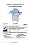
Assembly and Operating Instructions for
2 Burner with Side Burner Gas BBQ
Photographs are not to scale.
Specifications subject to change
without prior notice.
•
•
•
•
•
•
•
WARNING
•
•
Model KS0993
0359
For outdoor use only. Not for commercial use.
Use only Propane regulator 37mbar.
Read instructions before using the appliance. Failure to follow instructions could
result in death, serious bodily injury, and/or property loss.
Warning: accessible parts may be very hot. Keep young children away.
Do not move the appliance during use.
Turn off the gas supply at the gas bottle after use.
Any modification of the appliance, misuse, or failure to follow the instructions may
be dangerous and will invalidate your warranty. This does not affect your statutory
rights.
Retain these instructions for future reference.
Leak test your barbecue annually. Check the hose connections are tight and leak
test them each time you reconnect the gas bottle.
FOR YOUR SAFETY
If you smell gas:
1.
Shut off gas to the appliance.
2.
Extinguish any open flame.
3.
Open barbecue lid or hood.
4.
If odour continues, discontinue use and
contact your local dealer.
FOR YOUR SAFETY
1.
2.
Do not store or use petrol or other flammable
vapours or liquids in the vicinity of this or any
other appliance.
A gas bottle not connected for use shall not be
stored in the vicinity of this or any other
appliance.
PDF created with pdfFactory trial version www.pdffactory.com
A. Parts List
Quantities vary according to model purchased. Specifications subject to change without prior notice. For more details on
hardware, please see the corresponding Hardware Reference Diagram for your barbecue model.
CODE
A1
A2
A3
A4
A5
A6
A7
A8
A9
B1
B2
B3
B4
B5
B6
B7
B8
B9
B10
C1
C2
C3
D1
D2
D3
D4
D5
D6
D7
E1
E2
E3
E4
E5
E6
E7
E8
E9
E10
E11
E12
E13
PART
Lid
Lid handle
Cooking grill
Heat tent
Hinge
Burner
Firebowl
Grease cup hanger
Grease cup
Right front leg
Right rear leg
Left front leg
Left rear leg
Wheel
Left upper support
Right upper support
Control panel assembly
Front canvas
Bottom shelf
Side table
Side table front support
Side table rear support
Side burner assembly
Side burner knob
Side burner electrode
Side burner
Side burner grate
Side burner front support
Side burner rear support
M6*20 bolt
M6*12 bolt
ST4*10 bolt
M4 nut
Washer
M6 nut
M5*8 bolt
M6*15 Shoulder bolt
M4*8 bolt
Axle
Heat tent support
R-pin
M5 nut
2
PDF created with pdfFactory trial version www.pdffactory.com
QTY
1
1
1
1
2
1
1
1
1
1
1
1
1
2
1
1
1
1
1
1
1
1
1
1
1
1
1
1
1
8
20
10
2
2
8
8
4
3
2
1
2
6
B1. Parts Diagram
Quantities vary according to model purchased. Specifications subject to change without prior notice. For more details on
hardware, please see the corresponding Hardware Reference Diagram for your barbecue mode
A1
A2
A3
A4
A5
A5
A6
A7
D5
A8
B6
D4
B7
A9
B1
C1
D1
D7
F4
B4
B2
D2
D6
C3
B3
D3
B1
C2
B8
B5
B5
B9
B10
3
PDF created with pdfFactory trial version www.pdffactory.com
B2. Hardware Reference Diagram
Specifications subject to change without prior notice.
E2
E2 M6x12
M6x12BOLT
Bolt20PCS
20PCS
M6x20
Bolt
8PCS
E1E1M6x20
BOLT
8PCS
KS0993
E6M6
M6Nut
Nut8pcs
8PCS
E6
E5
E5Washer
Washer2PCS
2PCS
E7MM5x8
Bolt8PCS
8PCS
E7
5x8 BOLT
E4E4
M4MNut
4NUT2PCS
2PCS
E3
Bolt 6PCS
E3 ST4*10
ST4*10 6PCS
E9
M4x8Bolt
BOLT
3PCS
E9 M4x8
3PCS
E8 M6x15 Shoulder Bolt 4PCS
E10Wheel-Axle
Axle 2PCS2PCS
E10
E11 Heat tent support 1PCS
E12 R Pin 2PCS
4
PDF created with pdfFactory trial version www.pdffactory.com
E13M5M5
Nut6PCS
6PCS
E13
NUT
C. Assembly
TOOLS NEEDED FOR ASSEMBLY:
Medium size flat blade or Philips/cross-point screwdriver, adjustable spanner or metric spanner set
This barbecue requires two people for assembly. Please remove all packaging materials from all individual parts before
assembling. Please lay out all nuts and bolts and check lengths before assembling. Whilst every care is taken during the
manufacture of this product, care must be taken during the assembly in case sharp edges are present.
1
F3
F2
B4
B3
B10
F11
Fig 1
Fix the left front leg (B3) and left rear leg (B4) on the bottom shelf (B10) using M6*12 bolts (E2) as Fig 1 .
2
B2
F6
B1
F5
B10
Fig 2
Fix the right front leg (B1) and left rear leg (B2) on the bottom shelf (B10) using M6*12 bolts (E2) as Fig 2 .
5
PDF created with pdfFactory trial version www.pdffactory.com
3
B4
B3
E12
F10
B5
F9
F8
E10
Fig 3
Install the wheels (B5) to the left front leg (B3) and left rear leg (B4) using the axle (E10). Then fix the axle
(E10) by R pin (E12) as Fig 3 .
4
B6
F1
B7
F4
B4
B2
B1
B3
Fig 4
Connect the left upper support (B6) with the left front leg (B3) and left rear leg (B4) using M6*20 bolts (E1)
and M6 nuts (E6) as Fig 4.
Repeat the same connection of the right upper support (B7) with the right front leg (B1) and right rear leg (B2)
using M6*20 bolts (E1) and M6 nuts (E6) as Fig 4. Fix the bolts tightly by the screwdriver.
6
PDF created with pdfFactory trial version www.pdffactory.com
5
B7
B6
B8
F7
Fig 5
Fix the control panel assembly (B8) on the left upper support (B6) and right upper support (B7) using M6*12
bolts (E2) as Fig 5.
6
E11
A7
Fig 6
Fix the heat tent support (E11) on the firebowl (A7) using M4*8 bolts (E9) and M4 nuts (E4) as Fig 6.
7
PDF created with pdfFactory trial version www.pdffactory.com
7
A7
B6
B7
Fig 7
Set the firebowl (A7) on the left upper support (B6) and right upper support (B7) using M6*20 bolts (E1) as
Fig 7.
8
A6
A7
Fig 8b
Fig 8a
Put the burner (A6) through the hole of the firebowl (A7) as Fig 8a.
Align all valves on the control panel assembly (B8) against each venturi of the burner (A6). Make sure all
the valve tips go into the venturi tube completely with good alignment. Fix the burner (A6) on the firebowl
(A7) using ST4*10 bolts (E3) as Fig 8b.
Put the burner electrode in the valve on the control panel assembly (B8).
8
PDF created with pdfFactory trial version www.pdffactory.com
9
A5
Fig 9
Fix the hinge (A5) on the firebowl (A7) using M5*8 bolts (E7) and M5 nuts (E13) as Fig 9
10
A1
A1
E5
A2
A2
Fig 10
Put the washer (E5) between the lid handle (A2) and lid (A1). Align the holes and fix the lid handle (A1) on the
lid (A1) using M5*8 bolts (E7) as Fig 10.
9
PDF created with pdfFactory trial version www.pdffactory.com
11
Fig 11
Fix the lid (A1) and firebowl (A7) by the hinge (A5) using M5*8 bolts (E7) and M5 nuts (E13) as Fig 11.
12
C1
E1
C3
E2
C2
E3
Fig 12
Assemble the side table front support (C2) and side table rear support (C3) to the side table (C1). Secure the
supports with ST4*10 screws (E3) as Fig 12.
10
PDF created with pdfFactory trial version www.pdffactory.com
13
B7
B7
Fig 13a
Fig 13b
Install the side table assembly made on step 12 to the right upper support (B7) by M6*15 shoulder bolts (E8)
as Fig 13a and Fig 13b.
14
D1
D1
D7
D7
D6
D6
Fig 14
Fix the side burner front support (D6) and side burner rear support (D7) to the side burner assembly (D1)
using M6*12 bolt (E2) and lock the support narrow side by M6 nuts (E6) as Fig 14.
11
PDF created with pdfFactory trial version www.pdffactory.com
15
Fig 15
Fix the side table assembly (D1) to the left upper support (B6) using M6*12 bolts (E2) as Fig 15.
16
Fig 16a
Fig 16b
Loosen the pre-assembled screws on the side burner valve of the control panel assembly (B8) as Fig 16a.
Fix the side burner valve on the side burner panel bracket of the side burner assembly (D1) using the
screws as Fig 16b.
12
PDF created with pdfFactory trial version www.pdffactory.com
D4
D4
D5
D5
D3D3
Fig 16c
Fig 16e
Fig 16d
Electrode of Main Burner
Electrode of Side Burner
Fig 16f
Fig 16g
Fix the side burner electrode (D3) on the side burner assembly (D1) using M4*8 bolt (E9). Put the side burner
(D4) through the hole of side burner assembly (D1) as Fig 16c.
Adjust the burner venturi against the valve. Make sure the valve tip goes into the venturi tube completely with
good alignment. Then tighten the side burner (D4) on the side burner assembly (D1) using M4*8 bolt (E9) as
Fig 16d.
Put the side burner grate (D5) on the side burner assembly (D1) and align with 3 holes as Fig 16e.
Connect the side burner electrode (D3) to the valve of the control panel assembly (B8) as Fig 16f and 16g.
13
PDF created with pdfFactory trial version www.pdffactory.com
17
A8
Fig 17
Put the grease cup hanger (A8) through the hole on firebowl (A7) as Fig 17.
18
B7
A9
F12
B9
Fig 18
Hang the grease cup (A9) on the grease cup hanger (A8). Attach the Front Canvas (B9) to the left front leg
(B3) and right front leg (B1) as Fig 18. Secure the position with the velcro on canvas edge.
14
PDF created with pdfFactory trial version www.pdffactory.com
19
A3
A4
D2
Fig 19
Put the side burner knob (D2) on the side burner assembly (D1). Put the heat tent (A4) and cooking grill
(A3) on the firebowl (A7) as Fig 19.
20
Fig 20
Complete the assembly as Fig 20.
15
PDF created with pdfFactory trial version www.pdffactory.com
YOU MUST HAVE THE PROPER REGULATOR
AND BOTTLE IN ORDER FOR THE BARBECUE TO
OPERATE SAFELY AND EFFICIENTLY. USE OF
AN INCORRECT OR FAULTY REGULATOR IS
DANGEROUS AND WILL INVALIDATE ANY
WARRANTY. Please consult your local gas dealer
for the most suitable gas bottles.
D. Important Information
Please read these instructions carefully before
assembly and use.
• Retain these instructions for future reference.
• For outdoors use only – do not use indoors. Do
not use below ground level.
• For use with LPG bottled gas only. A regulator of
37mbar must be used for propane.
• Do not use within 1m of any flammable structure
or surface.
• LP gas cylinders should not be placed directly
underneath the barbecue.
• LP gas cylinders must not be stored or used in the
horizontal position. A leak would be very serious
and liquid could enter the gas line.
• When igniting barbecue open its hood before
lighting.
• Do not move the barbecue while alight.
• This barbecue must not be left unattended when
lit.
• The hood handle can become very hot. Grip only
the centre of the handle. Use of a cooking glove is
advised.
• Use caution when opening the hood, as hot
steam inside is released upon opening.
• Parts of this barbecue become very hot – care
must be taken when children, elderly people, and
animals are present.
• Always turn off the gas bottle when the barbecue
is not in use.
• Never cover a barbecue until it has completely
cooled.
• Never use the barbecue with the side shelf in the
down position.
• Leak test annually, and whenever the gas bottle is
removed or replaced.
• Do not store flammable materials near this
barbecue.
• Do not use aerosols near this barbecue.
• Failure to follow the manual’s instructions could
result in serious injury or damage.
• If you have any queries regarding these
instructions, contact your local dealer.
F. Installation
F1. Selecting a Location
This barbecue is for outdoor use only and should be
placed in a well-ventilated area. Take care to ensure
that it is not placed UNDER any combustible surface.
The sides of the barbecue should NEVER be closer
than 1 metre from any combustible surface. Keep
this barbecue away from any flammable materials!
F2. Precautions
Do not obstruct any ventilation openings in the
barbecue body. Secure the gas bottle on the cylinder
holder and always tighten it with the black strap
provided. Should you need to change the gas bottle,
confirm that the barbecue is switched off, and that
there are no sources of ignition (cigarettes, open
flame, sparks, etc.) near before proceeding. Inspect
the gas hose to ensure it is free of any twisting or
tension. The hose should hang freely with no bends,
folds, or kinks that could obstruct free flow of gas.
Apart from the connection point, no part of the hose
should touch any hot barbecue parts. Always inspect
the hose for cuts, cracks, or excessive wear before
use. If the hose is damaged, it must be replaced with
hose suitable for use with LPG and meet the national
standards for the country of use. The length of the
hose shall not exceed 1.5m. N.B.-The date on U.K.
hose is the date of manufacture, not the expiry date.
F3. Fixing the Regulator to the Gas Bottle
Confirm all barbecue control knobs are in the off
position. Connect the regulator to the gas bottle
according to your regulator and bottle dealer’s
instructions.
F4. Leak Testing (To be performed in a wellventilated area.)
Confirm all control knobs are in the off position. Open
the gas control valve on the bottle or regulator.
Check for leaks by brushing a solution of ½ water
and ½ soap over all gas system joints, including all
valve connections, hose connections and regulator
connections. NEVER USE AN OPEN FLAME to test
for leaks at anytime. If bubbles form over any of the
joints, there is a leak. Turn off the gas supply and
retighten all joints. Repeat test. If bubbles form again,
do not use the barbecue. Please contact your local
dealer for assistance. Leak test your barbecue
annually. Check the hose connections are tight and
leak test them each time you reconnect the gas
bottles.
E. Gas and Regulator
This barbecue can use only propane LPG bottled
gas. Propane bottles will supply gas all year round,
even on cold winter days. A spanner may be required
to change gas bottles. The bottle should never be
stood on the trolley base and placed directly under
the barbecue. Gas bottles should never be stored or
used laid on their side. Never store gas bottles
indoors.
16
PDF created with pdfFactory trial version www.pdffactory.com
G5. Lighting the Side Burner
• Keep side burner free.
• Set the control knob to off and turn on the gas
supply.
• Push in and turn the control knob anti-clockwise
to max position.
• Push the ignition button several times and the
burner should ignite.
• If the burner fails to ignite after above procedure,
turn the knob to the off position and close the gas
valve. Wait 5 minutes and then repeat the above
steps. If the barbecue still fails to light, please
refer to the manual ignition instruction in the
section below.
G. Operation
G1. Warning
• Before proceeding, make certain that you
understand the IMPORTANT INFORMATION
section of this manual.
G2. Preparation Before Cooking
To prevent foods from sticking to the cooking grill,
please use a long handled brush to apply a light coat
of cooking or vegetable oil before each barbecuing
session. (Note: When cooking for the first time,
paint colours may change slightly as a result.
This is normal and should be expected.)
G6. Manual Ignition Instruction for Side Burner
• Set the control knob to the off position.
• Apply a lit match on the gap to burner ports.
• Push and turn the control knob anti-clockwise to
max position and the burner should ignite. If the
burner fails to ignite, contact your local dealer for
assistance.
G3. Lighting the Main Burner
• Open the barbecue hood.
• Ensure all knobs are in the off position. Open the
gas control valve on the gas bottle or regulator.
• Push in and turn the burner control knob to the
Max position. Press the ignition button rapidly
several times until left portion of the burner is lit.
If burner fails to ignite, turn control knob to the off
position and turn gas off at the bottle or regulator.
Wait five minutes, then repeat the above steps.
After successful lighting of the left side, ignite the
remaining portion of the burner. If the burner fails
to ignite after following above procedure, turn all
the knobs to the off position. Close the gas valve
on the gas bottle. Wait 5 minutes, then repeat the
above steps. If the barbecue still fails to light,
please refer to the manual ignition instruction in
the section below.
• After ignition, the burner should be burned at the
high position for 3-5 minutes in order to preheat
the barbecue. This process should be done
before every cooking session. The hood (where
applicable) should be open during preheating.
• After completion of preheating, the burner should
normally be turned down to a lower position for
best cooking results.
G7. Roasting Hood Cooking
Barbecues equipped with a roasting hood give the
option of cooking with hood closed to form an ‘oven’
for roasting food, such as joints of meat, whole
chickens, etc.
When roasting, turn the burner under the food to the
OFF position. Close the hood and turn the other
burner down to a lower setting i.e. low to medium to
achieve the temperature required. DO NOT ALLOW
YOUR BARBECUE TO OVERHEAT. Avoid lifting the
hood unnecessarily as heat is lost each time the
hood is opened.
G8. End of Cooking Session
After each cooking session, turn the barbecue burner
to the “max” position and burn for 5 minutes. This
procedure will burn off cooking residue, thus making
cleaning easier. Make sure the hood is open during
this process.
G4. Manual Ignition Instruction for Main Burner
• Insert lit match through the match-lighting hole at
the bottom of the barbecue body.
• Push in and turn the rightmost control knob anticlockwise to the max position.
• After the right portion of the burner is lit, light the
remaining portion of the burner.
• If burner fails to ignite, contact your local dealer
for assistance.
• After ignition, the burner should be burned at the
max position for 3-5 minutes in order to preheat
the barbecue. This process should be done
before every cooking session. The hood (where
applicable) should be open during preheating.
• After completion of preheating, the burner should
normally be turned down to a lower position for
best cooking results.
G9. Turning Off Your Barbecue
When you have finished using your barbecue, turn all
the control valves fully clockwise to the “Off” position,
then switch off the gas at the bottle. Wait until the
barbecue is sufficiently cool before closing its hood.
H. CARE AND MAINTENANCE
Regularly clean your barbecue between uses and
especially after extended periods of storage. Ensure
the barbecue and its components are sufficiently cool
before cleaning. Do not leave the barbecue exposed
to outside weather conditions or stored in damp,
moist areas.
• Never douse the barbecue with water when its
surfaces are hot.
• Never handle hot parts with unprotected hands.
17
PDF created with pdfFactory trial version www.pdffactory.com
be treated with a rust inhibitor and painted with
barbecue paint or a heat resistant paint. Chrome
plated warming racks and grills should be coated
with cooking oil. Wrap the burners in aluminium foil to
help prevent insects or other debris from obstructing
the burners.
The gas bottle must be always be disconnected from
the barbecue and stored in a well ventilated area at
least 1 metre away from any fixed ignition source. Do
not store inside residential accommodation. Never
store cylinders below ground level (e.g. cellars). Do
not let children tamper with bottles.
H1. Cooking Grill
Clean with hot soapy water. To remove any food
residue, use a mild cream cleaner on a non-abrasive
pad. Rinse well and dry thoroughly.
H2. Burner Maintenance
Your burner has been preset for optimal flame
performance. You will normally see a blue flame,
possibly with a small yellow tip when the burner is
alight. If the flame pattern is significantly yellow, this
could be a problem caused by grease from cooking
blocking the burner or spiders or other insects in the
burner venturi. This can result in the flow of the gas
and air mixture being restricted or blocked which may
result in a fire behind the control panel causing
serious damage to your barbecue. If this happens,
the gas should be immediately turned off at the
bottle. Burners should be inspected and cleaned on
a regular basis in addition to the following conditions:
1) Bringing the barbecue out of storage.
2) One or more of the burners do not ignite.
3) The burner flame pattern is significantly yellow.
4) The gas ignites behind the control panel.
I. Technical Specifications
To clean a burner, remove it from the barbecue. The
outside of the burner can be cleaned with a wire
brush. Clean the portholes with a pipe cleaner or
piece of wire. Take care not to enlarge the portholes.
Clean the insect screen on the end of the venturi
tube with a bristle brush (i.e. an old toothbrush).
Clean the venturi tube with a pipe cleaner or piece of
wire. You may need a torch to see into the venturi
tube to make sure it is clear. ”Turn the burner up on
end and lightly tap against a piece of wood to
dislodge any debris from inside.”
Model Number
KS0993
Gas Category
I3P (37)
Type of Gas
Propane
Gas Pressure
37 mbar
Pin Number
359/BU/1016
Injector Size (Main Burner)
0.75mm
Injector Size (Side Burner)
0.74mm
Total Heat Input
7.0 kW
2 Burner Heat Input
4.7 kW
Side Burner Heat Input
2.3 kW
Gas Consumption
500 g/h
Country of Destination
GB and IE
This barbecue grill is manufactured by:
H3. Barbecue Body
Regularly remove excess grease or fat from the
barbecue body with a soft plastic or wooden scraper.
It is not necessary to remove all the grease from the
body. If you need to clean fully, use hot soapy water
and a cloth, or nylon-bristled brush only. Remove
cooking surfaces and burners before full cleaning. Do
not immerse the gas controls or manifold in water.
Check burner operation after carefully refitting into
body.
Donguang Kingsun Enterprises Co. Ltd.
Address: Xicheng Area 2, Shiyong Village, Hengli
Town, Dongguan City, Guangdong Province,
China
H4. Fixings
All screws and bolts, etc. should be checked and
tightened on a regular basis.
H5. Storage
Store your barbecue in a cool dry place. It must be
inspected on a regular basis as damp or
condensation can form which may result in damage
to the barbecue. It may be necessary to dry the
barbecue and the inside of the cover if used. Mould
can grow under these conditions and should be
cleaned and treated if required. Any rust that is found
that does not come into contact with the food should
18
PDF created with pdfFactory trial version www.pdffactory.com
L. Troubleshooting
Problem
Possible Cause
Solution
Burner will not light using the
ignition system
LP gas cylinder is empty
Replace with full cylinder
Faulty regulator
Have regulator checked or replace
Obstructions in burner
Obstructions in gas jets or gas hose
Clean burner
Clean jets and gas hose
Electrode wire is loose or disconnected on
electrode or ignition unit.
Reconnect wire
Electrode or wire is damaged
Change electrode and wire
Faulty pushbutton ignitor
Change ignitor
LP gas cylinder is empty
Replace with full cylinder
Faulty regulator
Have regulator checked or replace
Obstructions in burner
Clean burner
Obstructions in gas jets or gas hose
Clean jets and gas hose
LP gas cylinder too small
Use larger cylinder.
Obstructions in burner
Clean burner
Obstructions in gas jets or gas hose
Clean jets and gas hose
Windy conditions.
Use BBQ in a more sheltered position
Gas valve jammed
Replace gas valve
Burner will not light with a match
Low flame or flashback (fire in
burner tube— a hissing or
roaring noise may be heard)
Gas valve knob difficult to turn
Argos Limited, MK9 2W
19
PDF created with pdfFactory trial version www.pdffactory.com