1
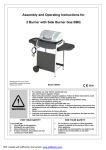
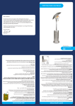
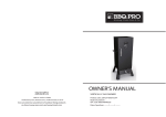
Assembly & User Instructions
Mirage 38,200Btu
Heat Focusing Patio Heater
These instructions are for your safety. Please read them
thoroughly before use and retain them for future reference
DANGER:
If you smell gas:
1. Shut off gas to the appliance.
2. Extinguish any open flame.
3. If odor continues, keep away from the
appliance and immediately call your gas
supplier or fire department.
WARNING:
Do not store or use gasoline or other
flammable vapors and liquids in the vicinity
of this or any other appliance.
An LP-cylinder not connected for use shall
not be stored in the vicinity of any other
appliance.
WARNING:
For Outdoor Use Only.
WARNING:
Improper installation, adjustment, alteration,
service or maintenance can cause
injury or property damage.
Read the installation, operating and
maintenance instuctions thoroughly before
installing or servicing this equipment.
We provide a Customer Support Service.
If you have any queries please contact us
on [email protected] or tel. (678) 534 2876
or visit our website www.uig.biz
Parts Supplied
Ref
Description
1
Base
Upper & Lower
Cylinder Chamber
2
Supports
A,B and C
Illustration Qty
Ref Description
Illustration Qty
1
7
Lower
Support Pole
1
3
8
Upper
Support Pole
1
ABC
3
Cylinder
Chamber Door
1
9
Lantern
1
4
Cylinder
Chamber Wall
1
10
Parasol Side
Panels
6
5
Cylinder
Chamber Top
1
11
Parasol Top
Panel
1
6
Reflector Handle
1
12
Regulator
1
Page 1
Fixings Supplied
Ref
Description
A M6 Nut
illustration
Qty Ref
Description
illustration
Qty
33
D M8
Washer
3
E M8x10 Bolt
3
B
M6x10 Dome
Head Bolt
27
C
M6x12 Dome
Hex Bolt
19
Before You Start
• Check the contents of the box and make sure you have all the parts and fittings
listed. If not, contact the Factory by email: [email protected]
or the Helpline (678) 534 2876
• When you are ready to start, make sure that you have the right tools at hand,
plenty of space and a clean dry area for assembly.
Assembly
• Please lay out all nuts and bolts and check lengths before assembly. It is
recommended that the carton is cut open and spread out on the floor and used as
a protective surface during assembly. Refer to the assembly diagrams as
necessary.
• Important - while every precaution has been made in the manufacture of this
product, care must be taken during assembly in case sharp edges are present.
Page 2
Assembly step 1
Base x 1
Upper & Lower
Cylinder Chamber
Supports (A,B,C)
M6 Bolt (C)
Fix the cylinder chamber supports. (A,B,C) to corresponding location on the
base with 6 M6 bolts (Ref. C).
Cylinder chamber
supports
Base
Page 3
Assembly step 2
Lower
Support Pole
M6 Nut (A)
M6x12
Dome Hex Bolt (C)
Fix lower support pole to cylinder chamber supports as shown
using 6 M6 bolts (Ref. C) and 6 M6 nuts (Ref. A)
M6x12 Bolt
Cylinder chamber
supports
Page 4
Assembly step 3
Cylinder
Chamber Wall
M6x10 Dome
Head Bolt (B)
M6Nut
(A)
Fit the cylinder chamber wall to the cylinder chamber supports
using 6 dome head bolts (Ref. B) and 6 M6 nuts (Ref. A)
Cylinder Chamber
Wall
Cylinder
Chamber
Supports
Page 5
Assembly step 4
Cylinder
Chamber door
Hang door on hinges. Ensure correct alignment and tighten
bolts securely.
Cylinder
Chamber door
Hinges
Page 6
Assembly step 5
Cylinder
Chamber Top
M6 x 10
Dome Bolt (B)
M6 Nut
(A)
Fit cylinder chamber top onto cylinder chamber support legs
using 3 dome head bolts (Ref. B) and M6 nuts (Ref. A)
Cylinder
Chamber Top
M6x10
Dome Head Bolts
Page 7
M6 Nut
Assembly step 6
M6 x 12
Dome Hex Bolt (C)
Fit upper support pole to lower suport pole using 3 x m6x12
dome hex bolts (Ref.C)
Upper
Support Pole
M6x12 Dome
Hex Bolts
Page 8
Assembly step 7
M6 x 12
Dome Hex Bolt (C)
1. Feed the lantern hose down the support pole and secure lantern to
support pole using 4 M6x12 Dome Hex Bolts. (Ref. C)
1
Lantern
M6x12 Dome
Hex Bolts
Page 9
Assembly step 8
Regulator
Connect the lantern hose to the regulator hose and secure tightly with
adjustable wrenches. Then attach the regulator to the cylinder, turn
clockwise to tighten it securely. Place cylinder in position as shown.
Connect
securely with
adjustable
wrenches
Check for Leak
Your patio heater has been checked at
all factory connections for leakage. To
check the connection at the gas
hose/regulator/cylinder
1. Make leakage solution by mixing
50% water with 50% liquid dish soap.
2. Brush several drops of the solution onto the gas
hose/regulator/cylinder and hose connection
3. Turn on the gas cylinder valve. Inspect the
connections and look for bubbles
4. If no bubbles appear the connection is safe
5. If bubbles appear there is leakage, loosen and
re-tighten this connection. If it still leaks,
please contact customer service on [email protected]
or (678) 534 2876
Screw regulator
onto gas
cylinder
Position
gas cylinder
inside cylinder
chamber
as shown
securing
with chain.
Points for leak testing
Hose / Regulator
Regulator / Cylinder
Note: The Cylinder must be positioned as shown in
the patio heater cylinder chamber to provide vapour
withdrawal.
Page 10
Assembly step 9
Reflector handle
Fitting reflector handle
1
2
R Clip
Retaining Pin
Heat focus
reflector bracket
Remove R clip and
retaining pin
Reflector handle
Fit reflector handle
3
Secure with retaining
pin and R clip.
Page 11
Assembly step 10
Top
Panel
Side
Panels
M8x10
Bolt
(E)
M8
Washer
(D)
Dome
Head Bolt
(B)
M6 Nut
(A)
Remove any protective layer and loosely screw parasol side panels
together overlapping as shown with 18 dome head bolts and nuts (B,A), fix the
top panel to the top of assembled side panels. Tighten all nuts. Fix assembled
parasol onto top of Parabolic Reflector Bracket using 3 M8x10 Bolts (E) and
M8 washers (D).
Top
Panel
Side
Panels
Burner
Head
Lantern
Use the reflector handle to
adjust the degree of reflector tilt.
Page 12
For all appliances:
• The heater, when installed, must be electrically grounded in accordance with local codes or, in the absence
of local codes, with the National Electrical Code, ANSI/NFPA 70, or the Canadian Electrical Code,
CSA C22.1.
• Certain materials or items, when stored under the heater, will be subjected to radiant heat and could be
seriously damaged.
• Inspect the visible portion of the hose before each use of the appliance. When portions of
the hose are located within the confines of the heater post, instructions to inspect the entire hose are
located within the confines of the heater post, instructions shall also include the proper procedure for leak
checking the connections upon re-assembly.
• Children and adults should be alerted to the hazards of high surface temperatures and should stay away to
avoid burns or clothing ignition.
• Young children should be carefully supervised when they are in the area of the heater.
• Clothing or other flammable materials should not be hung from the heater, or placed on or near the heater.
• Any guard or other protective device removed for servicing the heater must be replaced prior to operating
the heater.
• Installation and repair should be done by a qualified service person. The heater should be inspected
before use and at least annually by a qualified service person.
More frequent cleaning may be required as necessary. It is imperative that control compartment, burners
and circulating air passageways of the heater be kept clean.
• Keep the appliance area clear and free from combustible materials, gasoline and other flammable
vapors and liquids.
• Do not obstruct the flow of combustion and ventilation air.
• Keeping the ventilation opening(s) of the cylinder enclosure free and clear from debris.
• Clean the appliance, including special surfaces, with recommended cleaning agents, if necessary.
An appliance may be installed with shelter no more inclusive than:
a. With walls on all sides, but with no overhead cover.
b. Within a partial enclosure which includes an overhead cover and no more than two side walls. These side
walls may be parallel, as in a breezeway, or right angles to each other.
c. Within a partial enclosure which includes an overhead cover and three side walls, as long as 30 percent or
more of the horizontal periphery of the enclosure is permanently open.
The LP-gas supply cylinder to be used must be:
a. Constructed and marked in accordance with the specifications for LP-gas cylinders of the U.S. Department
of Transportation (DOT); or the Standard for cylinders, Spheres and Tubes for Transportation of Dangerous
Goods and Commission, CAN/CSA-B339, as applicable;
b. Provided with a listed overfilling prevention device; and
c. Provided with a cylinder connection device compatible with the connection for the appliance.
d. 20LP (9kg) cylinder. LPG capacity 4.7 gallons (17.8 litres) Cylinder Dimensions: Height 17.75 inches
(451mm) and width 12.25 inches (311mm)
e. The LP - gas cylinder used must include a collar to protect the cylinder valve.
A cylinder must be stored outdoors in a well-ventilated area out of reach of children. A disconnected cylinder
must have dust caps tightly installed and must not be stored in a building, garage or any enclosed area.
The pressure regulator and hose must be used and any replacement pressure regulator or hose must be
those as specified by the manufacturer.
Do not store spare LP-gas cylinder under or near this appliance.
Never fill the cylinder beyond 80 percent full; and for appliances designed to use a CGA No. 791 Connection:
‘Place the dust cap on the cylinder valve outlet whenever the cylinder is not in use. Only install the type of
dust cap on the cylinder valve that is provided with the cylinder valve.Other types of caps or plugs may result
in leakage of propane.
Page 13
Leak Testing
• To be performed in a well ventilated area.
• Confirm all control knobs are in the off position.
• Open the gas control valve on the bottle or regulator.
• Check the leaks by brushing a solution of 1/2 water and 1/2 soap over the gas
system joints, including all valve connections, hose connections and regulator
connections.
• NEVER USE AN OPEN FLAME to test for leaks at any time.
• If bubbles form over any of the joints, there is a leak.
• Turn off gas supply and retighten all joints.
• Repeat test. If bubbles form again, do not use the patio heater. Please contact
your local gas dealer for assistance or the helpline stated in this manual.
• Leak test annually and whenever the gas bottle is removed or replaced.
Gas and Regulator
• The gas hose must be connected in accordance with these instructions. When installed
correctly all parts of the hose should be contained within the Patio Heater pole and gas
cylinder chamber. No part of hose should be outside of the Patio heater body where it
could be a trip hazard or could be accidently damaged.
This appliance is for propane use only.
• See instructions supplied with regulator for correct use and attachment.
• Gas bottles should never be stored on their side.
• Never store gas bottles indoors.
• This appliance is supplied with a propane regulator which must only be
used for propane gas. NEVER use an adjustable regulator with this appliance.
• Please consult your gas dealer for the most suitable gas bottles for your regulator.
Siting Instructions
• This appliance is for OUTDOOR USE ONLY and should be placed in a well
ventilated area.
• A well ventilated area must have a minimum of 30% of its surface area open.
(Surface area is defined as the total surface of the walls surface.)
• The sides of the appliance should NEVER be closer than 40 inches (1m) from any
combustible surface.
• Keep this appliance away from any flammable materials!
• Important - Make sure the gas bottle is placed level within the base.
• Should you need to change the gas bottle, confirm the gas supply is turned off at
the regulator or bottle / cylinder valve, and there are no sources of ignition
(cigarettes, open flame, sparks, etc.) near before proceeding.
• For additional safety if required, fix heater securely through the holes in base to a
sound surface (fixings not supplied).
• Inspect the gas hose to ensure it is free from any twisting or tension. The hose
should hang freely with no bends, folds, or kinks that could obstruct free flow of
gas. Always inspect the hose for cuts, cracks, or excessive wear before use. If the
hose is damaged, it must be replaced with hose suitable for use with LPG and
meet the national standards for the country of use.
Connecting to the cylinder
• Confirm all control knobs are in the off position.
• Connect the regulator to the gas bottle according to your regulator and bottle
dealers instructions.
Page 14
Use Instructions
Before proceeding make sure you understand the warnings section of this manual.
Lighting instructions:
• Turn on gas supply at cylinder.
• Push dial in and turn to position
.
• While dial is held pressed in at position , press spark button repeatedly to ignite the burner.
• Hold dial in for at least 10 seconds to ensure heater stays lit.
• If burner does not light after holding dial in for 20 seconds wait 5 minutes and try again.
Do not continuously hold the dial in as you may cause a build up of gas.
• In windy conditions shield from wind to ensure easy lighting and hold dial in for at least 20
seconds to ensure heater stays lit.
• Turn control dial to high or low flame position as required.
• Correct operation of the burner is indicated by a predominantly blue quiet flame.
If the piezo sparker fails you can light your patio heater using a match.
To light Patio Heater with match:
1. Place lit match through the gap below the burner mesh and wind guard.
2. Turn the control dial to the
position. After burner igniteskeep control dial held
in for 10 seconds to ensure burner stays lit and then release.
3. If the burner does not light after holding the control dial in for 20 seconds with the lit
match in position, remove the match, turn the control dial to the off position, wait 5 minutes and
then repeat.
To Turn Off:
• Push dial in and turn to position
.
• Turn the gas off and disconnect at the cylinder when not in use.
Flame Characteristic
The flame pattern at the burner mesh should be visually checked whenever the heater
is operated. Normally the burner flame is blue with yellow flame at the top.
The Burner mesh will become red hot.
If flames extend beyond the surface of the burner mesh, or the phenomena of
flame lift or light back, or black spot is accumulating on the burner mesh or reflector,
the heater should be turned off immediately. The heater should not be operated again
until the unit is serviced or repaired.
Yellow Tip
Primary blue
flame
Reflector
Burner mesh
Care and Maintenance
• Regularly clean your patio heater between uses and especially after extended periods of storage.
• Ensure the heater control is turned fully to the off position. the gas supply is shut off at the regulator
or bottle / cylinder valve, and the heater and its components are sufficiently cool before cleaning.
• Never douse the heater with water when its surfaces are hot.
• We recommend that servicing of this appliance should be performed either after every 100
hours of use or annually, which ever is achieved soonest.
Fixings
All screws and bolts, etc, should be checked and tightened on a regular basis.
Storage
• Do not leave the patio heater exposed to outside weather conditions or stored in damp
moist conditions.
• To save space during long-term storage, the reflector can be removed. Take care to ensure
the shape of the reflector is not damaged or deformed, as this will affect performance.
Page 15
• When using the heater after extended periods of storage, re-attach the reflector.
The heater should never be operated without the reflector in place.
• If the heater is to be stored indoors, the gas bottle must be disconnected and left
outside. in a dry, well-ventilated area,away from any sources of heat or ignition.
• Do not let children tamper with the bottle.
Service
If your heater needs maintenance or is not working properly, please contact your local
authorized agent for service. It is a necessity to contact an authorized source for
replacement of parts and/or servicing. This work must be carried out by a qualified gas
technician. Spare parts may be obtained by contacting our spare parts department by
email: [email protected]
WARNINGS
• This product is for OUTDOOR USE ONLY
• NEVER use indoors, in an enclosed area or below ground level.
• This appliance is intended for use with LPG bottled gas only.
• This appliance has been supplied with a PROPANE REGULATOR (only use with Propane gas).
• NEVER use an adjustable regulator with this appliance.
• This appliance features a flame failure and tilt device. In the event of a wind blowing the flame out
or the unit being tipped over, the gas supply will be cut off from the cylinder. In this event, the knobs
should be set to off and you should wait 5 minutes before re-lighting.
• Failure to read and follow these instructions could result in serious injury or damage to property.
• This product will become hot when in use – take care when touching.
• Keep children and pets at a safe distance from the unit when in use.
• DO NOT move this product when in use.
• Any modification of this appliance may be dangerous.
• DO NOT use heater where the reflector is within 40 inches (1m) of any flammable structure or surface.
• NEVER operate the heater with the top half covered (burner head, reflector, etc.)
• DO NOT leave this product unattended when in use.
• Always keep the cylinder level and vertical when positioning inside the base.
• ONLY use this appliance on a flat LEVEL non flammable surface or ground. Positioning, ensure the
unit is a minimum of 40 inches (1m) from flammable items or structure from all sides and above.
• Always leak test the unit before use, annually, or after storage, when parts are replaced/serviced or if
the gas cylinder is removed or replaced.
• When storing the appliance or gas cylinder, ensure they are away from flammable materials or liquids.
• Regularly check that the regulator seal and hose is fitted and that it is in good condition. Replace
parts if necessary.
• Always follow the care and maintenance instructions – regularly maintain your appliance.
• Always replace worn parts – do not use the appliance if a leak, wear, or damage is found.
• DO NOT store or cover the appliance until fully cooled.
• DO NOT obstruct the ventilation holes of the cylinder housing.
• Always shut off the valve at the gas cylinder or the regulator before moving the appliance.
• In the event of high winds particular attention must be taken. Store the unit away or ensure it is at a
safe distance from other items in the event that the unit is blown over.
• Only use with gazebo’s specifically designed to be used with patio heaters.
• Ensure the heater is at a safe distance from glass and PVC doors and windows to stop damage from
any heat build up.
• Read the warnings and instructions use before operation.
Warning: Do not leave the heat focusing reflector of the
patio heater in the tilt position during rain or windy
conditions or when the patio heater is not in use or
unattended.
Always position the heat focusing reflector in the full
down position when not in use or during windy or rainy
conditions.
Page 16
CAUTION
• It is normal for the heater to smoke during the first few minutes of use.
• Regularly clean your patio heater after every use.
• If you smell gas – turn off the appliance and extinguish all flames. If the odour continues, immediately
contact your gas supplier.
• In the event of an uncontrollable fire, immediately disconnect the gas cylinder moving it away from fire
and contact
the fire services. DO NOT PUT YOURSELF AT RISK!
• Ensure aerosols are not used near this unit when in use.
• Ensure all packaging and plastic bags are disposed of safely.
Technical Data
Overall Height:
86.6'' approx.
Overall Weight:
77lbs
Overall Width:
34''
Heater Heat Input(∑Qn):
38,200 Btu/h
Heater Gas Consumption:
2.0 Lbs per hour
Heater Injector Size:
0.07”
Setting Pressure:
11” per W.C
Regulator Outlet Pressure:
11” per W.C
Standard
ANSI Z83.26a-2008 • CSA 2.37a-2008
Gas Fired Outdoor infrared Patio heaters
Gas Supply Pressure
Max.250 PSI, MIN.5 PSI
Specifications are subject to change without prior notice.
Universal Innovations,
Shall be used only in a well ventilated space
Kilcoole Ind. Est.,
and shall not be used in a building, garage or
Kilcoole,
any other enclosed area. Maybe installed in
Co. Wicklow,
shelter no more inclusive than:
Ireland.
40”(1M)
40”(1M)
–With walls on all sides but with no overhead
cover.
– Within a partial enclosure which includes an
overhead cover and no more than two side
walls. These side walls may be parallel, as in a
breezeway, or at right angles to each other.
– Within a partial enclosure which includes an
overhead cover and three side walls, as long
as 30% or more of the horizontal periphery of
the enclosure is permanently open.
Warranty
Keep these instructions for future reference.The patio heater has been manufactured under the highest standards of
quality and workmanship. We warrant to the original consumer purchaser that all aspects of this product will be free of
defects in material and workmanship for 1 year from the date of purchase. A replacement for any defective part will be
supplied free of charge for installation by the consumer. Defects or damage caused by the use of other genuine parts
are not covered by this warranty. This warranty shall be effective from the date of purchase as shown in the
purchaser’s receipt.
This warranty is valid for the original customer only and excludes product damage due to shipment or failure which
results from alteration, product abuse or product misuse whether performed by a contractor, service company, or
consumer. We will not be responsible for labor charges and/or damage incurred in installation, repair or replacement,
nor for incidental or consequential damage.
Contact: [email protected] Tel: (678) 534 2876
Page 17