1
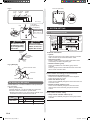
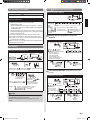
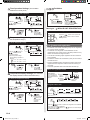
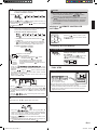
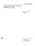
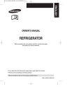
VRF SYSTEM
GROUP REMOTE CONTROLLER
(WIRED TYPE)
UTY-CGG
English
*
INSTALLATION MANUAL
For authorized service personnel only.
Contents
1. SAFETY PRECAUTIONS.............................................. 2
2. ACCESSORIES............................................................. 3
3. ELECTRICAL REQUIREMENT...................................... 3
4. SELECTING AN INSTALLATION LOCATION
4.1. Dimensions................................................................3
4.2. Name of parts............................................................3
5. INSTALLING THE REMOTE CONTROLLER
5.1. Flow of installation.....................................................4
5.2. Wiring.........................................................................4
5.3. Installation.............................................................. 5
5.4. Setting the DIP switch............................................ 6
6. SYSTEM SETTING
6.1. Explanation of terms............................................... 6
6.2. Turning on the power.............................................. 7
6.3. Setting.................................................................... 7
6.4. Remote controller settings................................. 7
6.5. Indoor unit registration........................................ 8
7. ERROR CODE DISPLAY............................................. 10
PART NO. 9374707072-05
9374707072-05_IM_en.indd 1
28/1/2554 16:00:34
1. SAFETY PRECAUTIONS
•• The “SAFETY PRECAUTIONS” indicated in the manual
contain important information pertaining to your safety.
Be sure to observe them.
•• For details of the operation methods, refer to the operating
manual.
•• Request the user to keep the manual on hand for future
use, such as for relocating or repairing the unit.
WARNING
This mark indicates procedures which, if
improperly performed, might lead to the
death or serious injury of the user.
•• Perform electrical work by an authorized service
personnel in accordance with the installation manual
and the electrical wiring regulations or implementation
regulations of the country. Also do not install this unit by
yourself. Improper electric work will cause electric shock
or a fire.
•• Perform installation work in accordance with the
installation manual. Request an authorized service
personnel to perform installation work. Do not install this
unit by yourself. Improper installation will cause injury,
electric shock, fire, etc.
•• In the event of a malfunction (burning smell, etc.),
immediately stop operation, turn off the electrical breaker,
and consult authorized service personnel.
•• Do not operate this unit when your hands are wet.
Touching the unit with wet hands will cause an electric
shock.
•• If children may approach the unit, take preventive
measures so that they cannot reach the unit.
This mark indicates procedures which,
if improperly performed, might possibly
CAUTION result in personal harm to the user or
damage to property.
•• Pay abundant care when transporting this unit because it
is a precision device. Improper transportation will cause
trouble.
•• Do not touch the switches with sharp objects. Doing so
will cause injury, trouble, or electric shock.
•• Do not expose this unit directly to water. Doing so will
cause trouble, electric shock, or heating.
•• Do not set vessels containing a liquid on this unit. Doing
so will cause heating, fire, or electric shock.
•• Dispose of the packing materials safely. Tear and dispose
of the plastic packing bags so that children cannot play
with them. There is the danger of suffocation if children
play with the original plastic bags.
•• Install a leakage circuit breaker to power supply cable
in accordance with the related laws and regulations and
electric company standards.
•• Use a power source exclusively for this unit. Never share
the power source with other electrical equipment. Doing
so will cause fire and electric shock.
Do not install the unit in the following areas:
•• Do not install the unit near a source of heat, steam, or
flammable gas.
•• Area filled with mineral oil or containing a large amount of
splashed oil or steam, such as a kitchen. It will deteriorate
plastic parts, causing the parts to fall or the unit to leak
water.
•• Area that generates substances that adversely affect the
equipment, such as sulfuric gas, chlorine gas, acid, or
alkali. It will cause the copper pipes and brazed joints to
corrode, which can cause refrigerant leakage.
•• Area containing equipment that generates
electromagnetic interference. It will cause the control
system to malfunction, preventing the unit from operating
normally.
•• Area that can cause combustible gas to leak, contains
suspended carbon fibers or flammable dust, or volatile
inflammables such as paint thinner or gasoline. If gas
leaks and settles around the unit, it can cause a fire.
•• Do not use the unit for special purposes, such as storing
food, raising animals, growing plants, or preserving
precision devices or art objects. It can degrade the quality
of the preserved or stored objects.
•• Install the unit in a well-ventilated place avoiding rains
and direct sunlight.
En-2
9374707072-05_IM_en.indd 2
28/1/2554 16:00:34
4.2. Name of parts
2. ACCESSORIES
The following installation parts are supplied. Use them as
required.
Name and Shape
Installation manual
Q’ty
●●With cover open
Application
This manual
Display panel
15
1
7
1
8
Instruction book
for operation
Operating manual
Label
4
10
3
11
4
1
9
2
12
5
Use this for writing the
names of the indoor units
that have been registered.
6
13
* The display is the same with the cover open or closed.
●●With cover closed
For installing the remote
controller
Screw
(M4 × 16 mm)
2
Binder
1
14
For remote controller and
remote controller cable
binding
Use of this product requires a special convertor and remote
controller cable.
These are provided as service parts, so please contact
authorized service personnel.
●●Display panel
16
17
18
19
20
21
23
22
3. ELECTRICAL REQUIREMENT
24
When connecting the Group remote controller and the
Convertor, use the following wiring.
Use
Remote
controller cable
Size
0.33 mm2
Wire type
22AWG
Polar 3 core,
Twisted pair
Remarks
Use shield
cable.
We recommend that you purchase our service parts for the
remote controller cable. Contact service personnel to
purchase this.
4. SELECTING AN INSTALLATION
LOCATION
4.1. Dimensions
Unit : mm (in.)
9
(11/32)
4.5 (3/16)
4.5
(3/16)
63.5 (2-1/2)
4.5 (3/16)
45.3
(1-25/32)
120 (4-3/4)
23
(29/32)
Hole
83.5 (3-9/32)
18
(23/32)
12.5
(1/2)
120 (4-3/4)
15.3
(5/8)
30
33.5
(1-3/16) (1-5/16)
6
(1/4)
Hole × 2
Hole × 3
25
26
27
” (All Timer Button)
1“ ” (Timer Mode/Delete Button)
2“ ” (Day Button)
3“ ”, “ ” (Set Time Button)
4“ ” (Program/Clock
5“ Adjust Button)
” (Enter Button)
6“ ” (All ON Button)
7“ ” (All OFF Button)
8“ ” (Start/Stop Button)
9“ ” (Select Button)
0“ a“ ” (Fan Control Button)
”, “ ” (Set Temperature Button)
b“ ” (Mode Button)
c“ d(ON/OFF Button)
eOperation Lamp
fDay Display
gSetting Display
hTransmission Display
iOperation Lock Display
jTemperature Display
kON/OFF Display
lTimer and Clock Display
mFan Speed Display
nRemote Controller Address Display
oTimer Mode Display
pIndoor Unit Operation Indicators
qOperation Mode Display
En-3
9374707072-05_IM_en.indd 3
28/1/2554 16:00:36
5. INSTALLING THE REMOTE
CONTROLLER
5.1. Flow of installation
The following is the flow of the installation of Group remote
controller.
• INSTALLATION
Wiring
Installation
• SETTING
•••••••• Refer to page 4
•••••••• Refer to page 5
Setting
the DIP switch
•••••••• Refer to page 6
Turning on
the power
•••••••• Refer to page 7
Setting
•••••••• Refer to page 7
Remote controller
settings
•••••••• Refer to page 7
Indoor unit
registration
• Setting the Group
Remote Controller Address
• Time Format Settings
• Timer Operation Settings
• Temperature Range Settings
• Temperature Display Settings
•••••••• Refer to page 8
5.2. Wiring
WARNING
•• Before starting installation work, turn off the power of this
unit and the connection destination. Do not turn on the
power again until installation is completed. Otherwise, it
will cause electric shock or fire.
•• Use the accessories or specified power cable and
connection cables. Do not modify power cable and
connection cables other than those specified, do not use
extension cords, and do not use independent branch
wiring. The allowable current will be exceeded and cause
electric shock or fire.
•• Install the connection cables securely to the terminal
block. Confirm that external force is not applied to the
wire. Use connection cables made of the specified wire.
If intermediate connection or insertion fixing are imperfect,
it will cause electric shock, fire, etc.
•• When connecting the power cable and transmission
cable, layout the wiring so that the cover of this unit is
securely fixed. If the cover is imperfectly fixed, it may
cause fire or overheating of the terminals.
•• Perform ground work positively. Do not connect the
ground wire to a telephone ground wire, water pipe, or
conductor rod.
•• Always fasten the outside covering of the connection cord
with the cord clamp. (If the insulator is chafed, electric
leakage may occur.)
•• When performing cable wiring work, be sure that it does
not touch the user. Doing so will cause injury or electric
shock.
•• If any cable is damaged, do not repair or modify it
yourself. Improper work will cause electric shock or fire.
CAUTION
•• Do not wire the remote controller cables and the
transmission cable together with or parallel to the
connection cable, transmission cables, and power supply
cables of the indoor and outdoor units. It may cause
erroneous operation.
•• When performing wiring work, be careful not to damage
the cable or injure yourself. Also, connect the connectors
securely. Loose connectors will cause trouble, heating,
fire, or electric shock.
•• Install the indoor and outdoor units, power cable, signal
cable and remote control cable 1 m away from television
and radio to avoid distorted images and noise.
•• Perform wiring so that water does not enter this unit along
the external wiring. Always install a trap to the wiring
or take other countermeasures. Otherwise it will cause
trouble or electric shock or fire.
•• Confirm the name of each unit and name of each terminal
block of the unit and connect the wiring in accordance
with the directions given in the manual so that there is no
incorrect wiring. Incorrect wiring will damage the electric
parts and cause smoke and fire.
•• When installing the connection cable near a source of
electromagnetic waves, use shielded cable. Otherwise, a
breakdown or malfunction could result.
En-4
9374707072-05_IM_en.indd 4
28/1/2554 16:00:37
(1)When connecting 1 Group remote controller
Convertor
Y1 Y2 Y3
When there is
ground cable
Remote
controller
cable
1 2 3
Group remote controller
•• Total remote controller cable length: MAX. 100 m (328 ft.)
Convertor
A+B+C+D+E+F
100m (328ft)
Remote controller cable
A
B
C
D
E
F
Group remote controller
(2)When multiple Group remote controllers are connected
•• A maximum of 4 Group remote controllers can be
connected with 1 Convertor.
•• Use of a terminal box is recommended when a junction
is made in the wiring.
Convertor
Y1 Y2 Y3
Remote
controller Terminal box
cable
Convertor
Y1 Y2 Y3
Remote controller cable
Terminal box
Group remote controller
Group remote controller
When connecting the group remote controllers to the
converter terminals, observe the following precautions.
•• Do not connect more than 4 remote control cables to
1 convertor.
•• Do not connect more than 1 remote control cable using the
same screw.
5.3. Installation
WARNING
•• Always use the accessories and specified installation
work parts. Check the state of the installation parts. Not
using the specified parts will cause units to fall off, water
leakage, electric shock, fire, etc.
CAUTION
•• Do not set the DIP switch or rotary switch of this unit
except as specified in this installation manual or the
instruction manual supplied with the air conditioner.
Setting the switches other than specified will cause an
accident or trouble.
•• Use an insulated screwdriver to set the DIP switches.
•• Before opening the case of this unit, completely discharge
static electricity charged on you body. Not doing so will
cause trouble.
•• Do not touch the circuit board and circuit board parts
directly with your hands. Otherwise, injury or electric
shock could result.
•• Tightening the mounting screws too tight will damage the
case of this unit.
•• Be careful so that the front cover does not fall after the
front cover screws are removed. Otherwise, injury could
result.
Open the operation panel on the front of the remote
controller, remove the 2 screws indicated in Fig. 1 and then,
remove the front case of the remote controller.
NOTES
When open the remote controller, remove the connector
from the front case. The cables may break if the connector
is not removed and the front case hangs down.
When installing the front case, connect the connector to the
front case. When removing and connecting the connector,
be careful not to break the cables. Be careful to insert the
connector completely.
(1)Pass the remote controller cable through the hole in the
rear case and connect the remote controller cable to the
remote controller terminal block specified in Fig. 2.
(2)Wrap the connector and remote controller cables with vinyl
tape or some other type of insulation as shown in Fig. 2.
(3)Clamp the remote controller cable sheath with the binder
as shown in Fig. 2.
(4)Cut off the excess binder.
(5)Install the rear case to the wall, box, etc., with 2 screws
(M4 × 16mm).
Fix the 2 screws in either horizontal or vertical position.
(Fig. 3)
Fig. 1
Front case (back side)
Rear case
•• Install at a place that can withstand the weight of the unit
and install positively so that the unit will not topple or fall.
•• When installing this unit, make sure that there are no
children nearby. Otherwise, injury or electric shock could
result.
•• After installing this unit, perform the test run to confirm
that the unit is operating properly. Then, explain the
operation of this unit to the customer.
Screws
Connector (CN1)
En-5
9374707072-05_IM_en.indd 5
28/1/2554 16:00:38
Fig. 2
Front case (back side)
1. 12V
(Red)
2. Signal
(White)
3. COM
(Black)
OFF
7
7
1
2
7
(9/32) (9/32) (9/32)
Unit : mm (in.)
1. 12V (Red)
2. Signal (White)
3. COM (Black)
Hole
Binder
DIP Switch
=
Tightening torque
0.8 to 1.2N • m
(8 to 12 kgf • cm)
Binder
CAUTION
Be careful to avoid
breaking the cable
by over-tightening
the binder.
ON
6. SYSTEM SETTING
6.1. Explanation of terms
System
CAUTION
When connecting
the remote controller
cables, do not overtighten the screws.
Remote
controller
group
Refrigerant
system
Refrigerant
pipe
Group remote
controller
Convertor
Indoor
unit
Wireless
Wired
remote controller remote controller
Outdoor unit
Transmission cable Controller cable
Wrap this
portion.
Controller related items
•• System:
This is all of the indoor units, outdoor units and controller
units connected by the same transmission cable.
•• Refrigerant system:
This is a system composed of indoor and outdoor units
connected by the same refrigerant pipe.
•• Remote Controller group:
This is the smallest unit controlled by group remote
controller.
This is a group of indoor units that have been connected
with a remote controller cable.
Insulation
Group remote
controller
Fig. 3 [Example]
Remote controller cable
Connector
Indoor / Outdoor unit setting (on the circuit board)
•• Refrigerant circuit address (0~99):
This is the ID individually assigned to each refrigerant
system and is used for control.
•• Indoor unit address (0~63):
This is the ID individually assigned to each indoor unit and
is used for control.
•• Remote controller address (0~15):
This is the ID individually assigned to the indoor units
forming each remote controller group and is used for
control.
Box
Rear case
Screws
5.4. Setting the DIP switch
Set DIP switch No. 1 to ON to enable the memory backup of
time information.
•• Memory backup setting
If the DIP switch No. 1 is not set to ON, the current time
information will be lost if there is a power failure.
*Registered information, such as that for the internal unit, is
not erased even if the DIP switch is turned off.
NO.
DIP switch
1
2
Switch state
OFF
Invalidity
Fixed at OFF
ON
Validity
(
Group remote controller setting
•• Group remote controller address (0~3):
This is the ID individually assigned to each group remote
controller.
Factory setting)
En-6
9374707072-05_IM_en.indd 6
28/1/2554 16:00:38
6.2. Turning on the power
6.4.
Remote controller settings
Remote Controller Settings
CAUTION
Initial Screen
•• Recheck the wiring. Incorrect wiring will cause trouble.
Turning on the power
Once the installation and wiring has been completed, use
the following procedure to turn on the power.
1. Install the front case.
*When installing the front case, connect the connector
to the front case (in 5. INSTALLING THE REMOTE
CONTROLLER).
2. Check the indoor and outdoor unit wiring and circuit
board switch settings, and then turn on the power of the
indoor and outdoor units.
(1) Turning on the power for all connected indoor units.
(2) Turning on the power for all connected outdoor units.
(3) Turning on the power for all connected convertor of
group remote controllers.
Wait for 1 minute or more after turning on the power before
performing the next section.
Remote Controller
Settings
●● To select the setting
DAY
Settings
:Setting the Group remote controller address → Page 7
:Time Format Settings → Page 7
:Temperature Range Settings → Page 8
:Timer Operation Settings → Page 8
:Temperature Display Settings → Page 8
, ,
: Forbidden → Page 8
Press the “ ”
button to select the
item to be set.
Setting the Group Remote Controller Address
To set the Group remote controller address
1 Decrement
Check that it is
Increment
.
6.3. Setting
Group remote controller address
Press the “ ” button or
“ ” button to set the
Group remote controller address.
* For each convertor,
make the settings in
order starting with
“00” according to the
number of Group remote
controllers connected.
Switching to the Settings Screen
Initial Screen
Flashing
Error code
(Refer to page 10.)
Flashing
Turn on
the power
2
1
Settings
Hold down the “ ” button and “ ” button simultaneously
for 2 seconds or more to start the Settings.
2
●● To complete Settings
If the indoor unit
is not registered,
01 and 00 will not
be displayed.
Press the “ ” button or “ ”
button to select the item to be set.
Settings : Remote controller settings → Page 7
: Indoor unit registration → Page 8
: Forbidden
,
,
,
,
,
NOTES
When there is a display other than the initial screen, it is
b possible that an error has occurred.
Please consult authorized service personnel in such
cases.
DAY
Press the
“ ”
button to move
“ Time Format
Settings”.
Time Format Settings (This switches the time format.)
To switch the time format
”
Hold down the “ ” button
button and “ simultaneously for
2 seconds or more to
complete the settings.
3
Press the
“ ”
button. Check
that
and
flash for
2 seconds.
1
Decrement Increment
Check that it is
Press the “ ” button or
” button to set the time
“ format setting.
.
Time format Setting
: 24 Hour Clock Display
: 12 Hour Clock Display 1
: 12 Hour Clock Display 2
2
Press the
“ ”
button. Check
that
and
flash for
2 seconds.
3
DAY
Press the
“ ”
button to move
to “ Timer
Operation
Settings.”
En-7
9374707072-05_IM_en.indd 7
28/1/2554 16:00:41
Time Operation Settings (This enables/
disables the weekly timer.)
1
Check that it is
2
.
Time operation setting
Press the “ ” button or
” button to set the
“ timer operation.
Enabled
3
Press the
“ ”
button. Check
that
and
flash for
2 seconds.
Forbidden
,
To move to the following settings
To enable/disable timer operation
Decrement Increment
,
DAY
Disabled
Press the
“ ”
button to
move to “
Temperature
Range Settings.”
1
DAY
●●
Forbidden
Press the “ ”
button to move to “
Time Format Setting.”
Moving to “
INDOOR UNIT REGISTRATION”
To move to indoor unit registration
Press the “ ” button once or press the
“ ” button 7 times to move to indoor
unit registration.
Temperature Range Settings (This changes ●● ,
Forbidden
Press the “ ”
button to move to “
Setting the Group remote
controller address.”
the temperature range.)
To set the temperature range
1
Decrement Increment
Check that it is
.
Temperature range setting
” button or
Press the “ ” button to set the
“ temperature range.
●● The temperature range
set for heating operation is
different.
: 10 °C – 30 °C (48 °F – 88 °F)
: 16 °C – 30 °C (60 °F – 88 °F)
2
3
Press the
“ ”
button. Check
that
and
flash for
2 seconds.
DAY
Press the
“ ”
button to
move to “
Temperature
Display Settings.”
Temperature Display Settings (This switches the display between Celsius and Fahrenheit.)
To switch the temperature display
1
Decrement Increment
Check that it is
.
6.5.
Indoor unit registration
•• A maximum of 8 remote controller groups can be registered
for a Group remote controller.
•• A maximum of 2 refrigerant circuit addresses can be
registered for each group remote controller (maximum of 4)
that is connected to a single convertor.
•• The remote controller groups registered can be monitored
and controlled.
•• Confirm the number set and location (room) for each indoor
unit with the user.
•• Perform registration after connecting the indoor units to be
registered to the respective outdoors units and turning on
the power.
•• Cannot be operated within 4 minutes after the start up.
Indoor unit registration screen
1
Initial Screen
See Explanation of 2 Refrigerant
circuit
terms on page 6 for
explanations of each address
address.
4 Remote
controller
address
3
Registration
position
Indoor unit
address
To register indoor units
Press the “ ” button or
” button to set the
“ temperature display.
2
Press the
“ ”
button. Check
that
and
flash for
2 seconds.
Temperature display setting
Celsius
3
DAY
1 ●● Registration position selection
Fahrenheit
Press the
“ ”
button three
times to move to
“ Setting the
Group remote
controller
address.”
Press the “ indoor unit
” button to select the position for registering the
2 ●● Refrigerant circuit address selection
DAY
Press the “ ” button to select the refrigerant circuit address
for the indoor unit being registered.
” button or “ ” button to scroll through
• Hold down the “ the addresses quickly.
En-8
9374707072-05_IM_en.indd 8
28/1/2554 16:00:43
a remote controller group made up of a single
3-1 When
indoor unit is registered, select the indoor unit address.
●● Indoor unit address selection
Decrement Increment
Press the “ ” button or “ ” button to select the indoor unit
address for the indoor unit being registered.
” button or “ ” button to scroll through
• Hold down the “ the addresses quickly.
a remote controller group made up of multiple
3-2 When
indoor units is registered, the remote controller address
and the indoor unit address are selected.
NOTES
(1)Be careful not to end the settings or switch the
” button.
indoor unit before pressing the “ Otherwise, the changed settings will be lost.
(2)If
is displayed during the registration of an indoor
unit, the Group remote controller address, refrigerant
circuit address, or indoor unit address may incorrect.
Check again.
Moving to “
SETTINGS”
REMOTE CONTROLLER
To set the remote controller
●● Remote controller address selection
Press the “ ” button 7 times or press
” button once to move to remote
the “ controller settings.
•• Please set Remote controller address start from “ ”
to “ ” in turn.
•• An indoor unit, of which Remote controller address is
“ ”, is automatically set to “Master unit” in a Remote
controller group consisting of multiple indoor units.
●● Indoor unit address selection
Completing All of the Settings
Decrement Increment
To complete Settings
•• When the remote controller
settings and indoor unit settings
are complete
Refrigerant circuit address
Indoor unit address
ex.: Refrigerant circuit address “
controller address “ ”
Remote
controller
address
Hold down again the “ ” button and
” button simultaneously for
“ 2 seconds or more to complete Settings.
”, remote
* The refrigerant circuit address is the same
as the address for the indoor unit set first
(remote controller address “ ”) and cannot be
changed.
1. Press the “ ” button
to select the remote controller address of the indoor unit being
registered.
” button or “ ” button to select the indoor
2. Press the “ unit address of the indoor units in the same remote controller
group that is being registered.
3. Repeat steps 1 and 2 to register all the indoor units in this
remote controller group.
4
FINAL STEP
To apply the label
Flashing
Press the “ ” button to register the selected indoor unit.
,
Check that the refrigerant circuit address, indoor unit address,
and registration is completed when
stops flashing (flashes for
4 minutes). After the start up for 4 minutes, indoor unit cannot be
registered.
” button during this time to cancel
• Press the “ the registration.
Label (Accessories)
84 × 21 (3-9/32 × 13/16)
Write the name of the indoor unit or the room where it is installed on
the label, and apply it to the Group remote controller.
• Consult the customer about the names to be written on the label.
• Explain to the customer about the indoor units that have been registered to each button.
5
Repeat steps from 1 to 4 to register other indoor units.
●●To delete the registered settings
1. Press the “ ” button during steps 2 to 3
reset the contents of the registration. (If the currently displayed
indoor unit is part of a remote controller group with multiple
units, only the settings for this indoor unit are reset.)
” button to delete the contents of the
2. Press the “ registration.
3. Please delete Remote controller address with the exception of
“ ” before delete Remote controller address “ ”.
En-9
9374707072-05_IM_en.indd 9
28/1/2554 16:00:45
7. ERROR CODE DISPLAY
The air conditioning system must be inspected if “E ✽ : ✽✽ ”
(error code) appears on the Timer and Clock Display, or the
operation lamp is flashing.
The following explains the meaning of each of the error codes.
Model code
Error code
Ex. Error code display
Model code
:
:
:
:
Outdoor unit
Indoor unit
Group remote controller
Convertor
For details on the error displays
for the indoor and outdoor units,
refer to the applicable Installation
Manual.
Error code table of Controller and Convertor
Error Code
12
14
15
26
28
C1
C4
CA
Contents
Remote controller communication error
Network communication error
Scan error
Address setting error
Other setting error
Main PCB error
Group remote controller hardware error
EEPROM error
NOTES
When “
” is displayed on the time display, it means
that the priority is given to the bus. In this case, the
remote controller is not operative.
In case “ ” is indicated, it means under maintenance.
When the indoor unit registration is performed by the
System Controller, Touch Panel Controller, etc., “ ” may
be displayed up to 15 minutes after the completion of
maintenance.
En-10
9374707072-05_IM_en.indd 10
28/1/2554 16:00:45