Transcript
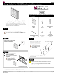
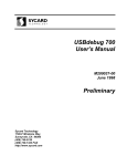
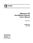
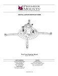
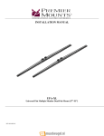
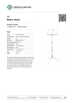
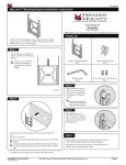
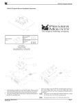
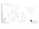
UNI-EMP UNI-EMP Equipment Management Plate Installation Instructions Introduction The UNI-EMP Equipment Management Plate fits perfectly inside the integrated GearBox™ of Premier Mounts’ line of universal short throw projector wall mounts and digital signage mounts. Use it to compactly organize and secure the Premier Mounts’ compact power amplifier and/or additional A/V equipment and wiring as needed. 3130 East Miraloma Avenue, Anaheim, CA 92806 USA USA and Canada Phone: 1.800.368.9700 Fax: 1.800.832.4888 Lock-It™ security screws are included for enhanced security. [email protected] Step 1 Projector mount shown is for example purposes only. Parts List Zip Ties (Qty 12) Remove the side doors and electronic and electrical components from inside the GearBox™. UNI-EMP Equipment Management Plate (Qty 1) M4 x 8mm Lock-It™ Security Screw (Qty 4) M5 Security Allen Wrench (Qty 1) Step 3 These instructions assume the GearBox™ is attached to the wall. See installation instructions for the mount if needed. Remove the side doors from the GearBox™. the compact power amplifier and/or other electronic and electrical ®® Remove components from inside the GearBox™. Are you installing Premier Mounts’ compact power amplifier? If Yes, continue to If No, go to Step 2 Step 3 your electronic Place components onto the UNI-EMP. the electronic components ®® Align so that the weight is distributed as evenly as possible. the zip ties through the ¯¯ Run mounting slots on the UNI-EMP, underneath the UNI-EMP and up through the mounting slots on the other side of the electronic components. the zip ties down and cut °° Tighten off any excess zip tie. electrical wiring to the ±± Attach electronic components. Step 4 Step 2 Depending on space, you may attach equipment and/or wiring to the back of the UNI-EMP. Small screws and flat washers may also be used to fasten the electronic components. Back of the UNI-EMP the UNI-EMP inside at Place the center of the GearBox™. 4-40 x ¼” Phillips flathead screws You can insert the UNI-EMP with either side facing the front the mount depending on your installation needs (Figure 1). Inside the Mount or four (4) M4 x 8mm Lock®® Use It™ security screws to attach the UNI-EMP to the inside bottom of the GearBox™ (Figure 2). Front of the UNI-EMP Four UNI-EMP screw holes should be accessible through the GearBox™ center screw holes. Figure 1 Bottom View of the UNI-EMP Compact Power Amplifier Use two (2) 4-40 x ¼” Phillips flathead screws to attach the compact power amplifier to the UNI-EMP (see drawing). The amp can be installed on either side of the UNI-EMP. Make sure you can later access the amp’s line and mic gain controls using a #1 flat blade screwdriver through both the diagonal slots of the GearBox™ and the circular slots of the UNI-EMP. Installation Instructions 9533-019-001-00 Insert M4 x 8mm Lock-It™ security screws Step 5 Re-attach the side doors of the GearBox™. Visit Premier Mounts website at http://www.mounts.com Figure 2