1
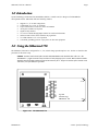
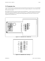
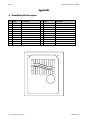
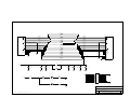
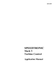
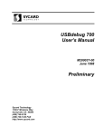
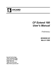
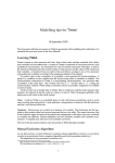
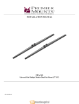
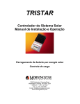
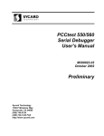
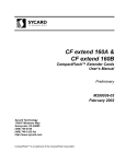
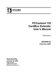
SMextend 750 SmartMedia Extender User’s Manual Preliminary M200042-00 July 1998 Sycard Technology 1180-F Miraloma Way Sunnyvale, CA 94086 (408) 749-0130 (408) 749-1323 FAX http://www.sycard.com SMextend 750 User’s Manual Page 1 1.0 Introduction Sycard Technology's SMextend 750 SmartMedia (SSFDC) extender card is a debug tool for SmartMedia development and test. SMextend offers the following features: • • • • • • • • • Supports 3.3, 5V or dual voltage hosts Configurable for 3.3V or 5V operation 4 layer construction to insure low noise environment All 22 pins available as test points Signals clearly marked Vcc can be isolated through jumper blocks for current measurements Surface mount resistors can be added to any signal line Vcc LEDs indicate 3.3V or 5V operation Convenient grounding posts for scope probes or other test equipment 2.0 Using the SMextend 750 The SMextend 750 must be configured for 3.3, 5.0, or dual voltage operation prior to use. Section 2.1 describes the procedure for first time setup. Caution: Caution Insertion and removal of the extender and SmartMedia card should be done with care. The SmartMedia’s fragile connectors may be broken or bent if improper force is used. Both card and extender should be inserted straight without any lateral movement or force. Proper care and use of the extender card will insure years of trouble free operation. GND Vcc VCC CE# RE# R/B# OP LVD JP2 D7 D6 D5 D4 JP3 VCC GND CLE ALE WE# WP# D0 D1 D2 D3 GND GND 3.3V Sycard Technology SMextend 750 5V JP4 GND VCC 5V LED EN Figure 2.0-1 The SMextend 750 M200042-00 1998 Sycard Technology Page 2 SMextend 750 User’s Manual 2.1 Preparing the SMextend 750 for use As shipped from the factory the SMextend 750 is configured with voltage keys disabled. In this condition, the SMextend may not be accepted into many SmartMedia sockets. The SmartMedia standard defines two voltage keys, one for 3.3V and one for 5V. 3.3V only cards have a cutout corner adjacent to pin 22 of the connector. 5V only cards have a cutout adjacent to pin 12. Cards that can operate at both 3.3V and 5V have both cutouts. The following section describes how to configure the SMextend for the desired operating voltage. 2.1.1 Removing the voltage key. The 3V key should be removed if the card is to be used in a 3.3V host. The 5V key should be removed for 5V hosts. The voltage key can be removed with a small pair of pliers or a wire cutter. The SMextend 750 PCB is scored along the proper cut marks. After the user removes the keys, it may be necessary to clean the freshly cut edge of the board with a small file. Some sockets may not accept the SMextend 750 if these edges are not smooth. Note: Note Once removed, the voltage keys cannot be reattached. 2.2 Using the SMextend Use of the SMextend 750 is fairly straightforward. The SMextend is inserted into the host socket with the connector pattern in the correct orientation. The SmartMedia card is then inserted, with the connector pattern facing down, into SMextend 750’s socket. Caution: Caution The SMextend socket is keyed to accept both 3.3V and 5V SmartMedia cards. This configuration could allow a 3.3V only card to be plugged into a 5V host causing damage to either the card or the host. The user should verify compatibility by first trying to inserting the SmartMedia card into the host prior to using the extender card. 2.3 Test points All 22-pins of the interface are available to probe through clearly marked headers. The headers are standard 0.1” dual row headers with 0.025” posts designed to accept a wide variety of test probes and cable assemblies. 2.4 Power Indicators Two LED power indicators display the status of the socket’s Vcc. The PWR LED indicates that power is applied to the board. When both the PWR LED and the 5V LED are lit, a Vcc of greater than approximately 3.5V is present. When only the PWR LED is lit, the Vcc is at a level of less than 3.5V. Note: Note The power LEDs are designed to indicate the presence of power on the Vcc supply pins. The LEDs do not provide an accurate measurement of Vcc. Use a voltmeter to determine the actual operating voltage. In some low power applications, the current drawn by the power LEDs (10-20mA) may cause problems. The SMextend is capable of disabling the LED voltage indication by removing the jumper labeled LED EN at JP4. 2.5 Current Measurements The Vcc power bus may be isolated from the SmartMedia Card socket through two jumper blocks labeled JP2 and JP3. Both jumpers must be removed to isolate the power. A current meter can be inserted to measure card current consumption. Caution: Caution Care must be taken to insure that the current measuring device is inserted before turning on power to the host socket. Improper power sequencing may cause a damaging latchup condition. 1998 Sycard Technology M200042-00 SMextend 750 User’s Manual Page 3 2.6 Termination Area An area with SMT resistors is located between the test points and the card connector allows access to all SmartMedia signals. A series of surface mount pads allows the user to isolate a signal by cutting a trace. The user may also add series resistors to any signal. When shipped from the factory, the resistor pads are shorted with PCB traces. In order to insert series resistor, these traces must be cut prior to soldering the resistor to the board. Figure 2.3-1 illustrate the termination areas located on the back of the SMextend board. Use this guide when making modifications to the board, since the silk-screen designations may be difficult to read. 3V 22 12 1 11 R14 CLE CE# R13 R15 ALE RE# R12 R16 WE# R/B# OP R11 R18 WP# R10 R17 D0 LVD R9 R1 D1 D7 R8 R2 D2 D6 R7 R3 D3 D5 R6 D4 R5 5V Figure 2.6-1 Termination Area - Solder Solder Side R14 CLE CE# R13 R15 ALE RE# R12 R16 WE# R/B# R11 R18 WP# OP R10 R17 D0 LVD R9 R1 D1 D7 R8 R2 D2 D6 R7 R3 D3 D5 R6 D4 R5 Figure 2.6-2 Termination Area - Close-up M200042-00 1998 Sycard Technology Page 4 SMextend 750 User’s Manual Appendix A. SmartMedia Pin Description Pin 1 2 3 4 5 6 7 8 9 10 11 Name Vss CLE ALE WE# WP# D0 D1 D2 D3 Vss Vss Description Ground Command Latch Enable Address Latch Enable Write Enable Write Protect Address/Data Bit 0 Address/Data Bit 1 Address/Data Bit 2 Address/Data Bit 3 Ground Ground / Card Detect Pin 12 13 14 15 16 17 18 19 20 21 22 Name Vcc D4 D5 D6 D7 LVD GND R/B# RE# CE# Vcc Description Power Address/Data Bit 4 Address/Data Bit 5 Address/Data Bit 6 Address/Data Bit 7 Low Voltage Detect Ground Ready / Busy# Read Enable Card Enable Power 5V 1998 Sycard Technology 3V 1 11 22 12 M200042-00 SMextend 750 User’s Manual Page 5 B. SMextend 750 Schematic M200042-00 1998 Sycard Technology P1 CLE ALE WE WP IO0 IO1 IO2 IO3 CD IO4 2 3 4 5 6 7 8 9 11 13 CLE ALE WE# WP# AD0 AD1 AD2 AD3 IO5 IO6 IO7 LVD OP R/B RE CE VCC VCC GND GND 14 15 16 17 18 19 20 21 12 22 1 10 AD5 AD6 AD7 LVD OP R/B# RE# CE# AD4 R14 0 R15 0 R16 0 R18 0 R17 0 R1 0 R2 0 R3 0 AD4R 2 3 4 5 6 7 8 9 11 13 R5 0 R6 0 R7 0 AD5R AD6R AD7R LVDR OPR R/BR# RER# CER# 14 15 16 17 18 19 20 21 IO5 IO6 IO7 LVD OP R/B RE CE R8 0 R9 0 R10 0 23 24 25 26 3VSW1 3VSW2 5VSW1 5VSW2 R11 0 R12 0 12 22 1 10 VCC VCC GND GND R13 0 VCC SSFDC J1 CLE ALE WE WP IO0 IO1 IO2 IO3 CD IO4 CLER ALER WER# WPR# AD0R AD1R AD2R AD3R VCC1 SSFDC CONN OP and CD# are optional power pins. JP2 VCC1 VCC JUMPER C1 0.1uF C3 0.1uF C4 0.1uF JP3 C5 0.1uF C6 0.1uF C2 0.1uF C8 0.1uF JUMPER VCC 5V LED JP4 D1 D2 R20 RED LED 110 VCC JUMPER 1N5226 3.3V Zener SOT23 VCC LED VCC D3 R19 YELLOW LED 330 CE# RE# R/B# OP LVD AD7 AD6 AD5 AD4 JP1 1 2 3 4 5 6 7 8 9 10 11 12 13 14 15 16 17 18 19 20 21 22 HEADER 11X2 CLE ALE WE# WP# AD0 AD1 AD2 AD3 Sycard Technology Title File = ORCAD31\SSFDC\SSFDC1.S31 SSFDC EXTENDER Size Document Number B 140031 Date: May 22, 1998 Sheet 1 of REV A 1