1
INSTALLATION
MANUAL
Installation Manual
Rooftop Package Units
Installationshandbuch
Kompaktanlage Für Dachmontage
Deutsch
Manuel D’installation
Conditionneurs D’air En Toiture
Français
Installatiehandboek
Compactsysteem Voor Dakmontage
Manual De Instalación
Unidades Del Conjunto Del Tejado
Manuale Di Installazione
Unità A Pacchetto Per Installazione Sul Tetto
Model:
UATYQ250MCY1
UATYQ350MCY1
UATYQ450MCY1
UATYQ550MCY1
UATYQ600MCY1
UATYQ700MCY1
English
Manual De Instalação
Unidades De Conjuntos De Telhado
Руководство По Установке
Компактные Установки Для Кондиционирования
Воздуха, Монтируемые На Крыше Здания
Instrukcja instalacji
Urządzenia dachowe (typu „rooftop”)
Kurulum kılavuzu
Çatı Tipi Ambalaj Üniteleri
Installationsmanual
Paketenheter för Takovansidor
Nederlands
Español
Italiano
Português
Русский
Polski
Türkçe
Svenska
IM-5RTBR-0710(0)-DAIKIN (DENV)
Part No.: R08019035377
IM-5RTBR-0710(0) COVER EN.indd 1
8/17/10 2:17:32 PM
ENGLISH
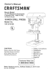
OUTLINE AND DIMENSIONS
Model: UATYQ250
Original Instruction
All dimensions are in mm
437
786
850
437
1275
544
379
513
85
2063
22
SUPPLY AIR
45
779
51
2181
214
DRAIN PIPE Ø 1"
872
98
154
398
405
RETURN
AIR
1052
369
180
117
788
97
FOR HORIZONTAL DISCHARGE
171
779
Back view of the unit:
1638
1660
384
VERTICAL
SUPPLY
AIR
133
537
1150
513
VERTICAL
RETURN
AIR
171
408
2131
FOR VERTICAL DISCHARGE
CENTER OF GRAVITY
1
IM-5RTBR-0710(0)-EN.indd 1
8/18/10 4:54:03 PM
Model: UATYQ250 WITH ECONOMIZER OPTION
437
786
437
All dimensions are in mm
544
379
513
85
2063
180
117
808
22
191
369
RETURN AIR
398
1052
779
405
SUPPLY AIR
51
872
2181
154
214
DRAIN PIPE ø 1"
98
OUTDOOR AIR
788
FOR HORIZONTAL DISCHARGE
1638
779
384
1660
513
VERTICAL
RETURN AIR
VERTICAL
SUPPLY
AIR
133
223
537
1150
672
277
Back view of the unit:
522
OUTDOOR AIR
97
171
171
408
2131
FOR VERTICAL DISCHARGE
2
IM-5RTBR-0710(0)-EN.indd 2
8/18/10 4:54:08 PM
ENGLISH
Model: UATYQ350
All dimensions are in mm
2180
342
1546
1000
342
1410
651
544
614
2113
136
22
630
SUPPLY AIR
405
58
168
213
395
RETURN
AIR
DRAIN PIPE ø 1"
1161
2230
99
250
207
265
1070
FOR HORIZONTAL DISCHARGE
630
187
164
Back view of the unit:
2209
1028
VERTICAL
SUPPLY
AIR
280
538
CONTROL
BOX
613
614
VERTICAL
RETURN
AIR
164
407
FOR VERTICAL DISCHARGE
CENTER OF GRAVITY
3
IM-5RTBR-0710(0)-EN.indd 3
8/18/10 4:54:10 PM
Model: UATYQ350 WITH ECONOMIZER OPTION
All dimensions are in mm
342
1546
342
2180
223
614
136
2113
22
651
207
544
630
405
250
265
709
58
2230
99
DRAIN PIPE ø 1"
1161
OUTDOOR AIR
168
RETURN AIR
213
395
SUPPLY AIR
1069
FOR HORIZONTAL DISCHARGE
164
630
187
OUTDOOR AIR
Back view of the unit:
2209
613
614
VERTICAL
RETURN AIR
VERTICAL
SUPPLY AIR
280
175
538
CONTROL
BOX
1028
710
166
562
164
407
FOR VERTICAL DISCHARGE
4
IM-5RTBR-0710(0)-EN.indd 4
8/18/10 4:54:14 PM
ENGLISH
Model: UATYQ450
All dimensions are in mm
2180
342
1546
1000
342
1385
544
651
614
136
2113
22
58
DRAIN PIPE ø 1"
1161
2230
99
168
264
395
RETURN
AIR
630
SUPPLY AIR
405
328
235
265
1069
164
630
187
FOR HORIZONTAL DISCHARGE
Back view of the unit:
2209
1130
VERTICAL
SUPPLY
AIR
280
538
CONTROL
BOX
613
614
VERTICAL
RETURN
AIR
164
407
FOR VERTICAL DISCHARGE
CENTER OF GRAVITY
5
IM-5RTBR-0710(0)-EN.indd 5
8/18/10 4:54:17 PM
Model: UATYQ450 WITH ECONOMIZER OPTION
All dimensions are in mm
342
1546
342
2180
223
544
651
614
2113
136
58
630
405
328
22
235
265
709
2230
99
DRAIN PIPE ø 1"
1161
OUTDOOR AIR
168
RETURN AIR
264
395
SUPPLY AIR
1069
FOR HORIZONTAL DISCHARGE
164
630
187
OUTDOOR AIR
Back view of the unit:
2209
613
614
VERTICAL
RETURN AIR
VERTICAL
SUPPLY
AIR
280
237
538
CONTROL
BOX
1130
710
207
562
164
407
FOR VERTICAL DISCHARGE
6
IM-5RTBR-0710(0)-EN.indd 6
8/18/10 4:54:21 PM
ENGLISH
Model: UATYQ550/600/700
All dimensions are in mm
2739
342
1547
1000
342
1735
586
558
610
2670
187
23
268
48
B
509
RETURN
AIR
2789
C
DRAIN PIPE ø 1"
99
168
405
SUPPLY AIR
1162
1069
FOR HORIZONTAL DISCHARGE
770
201
172
Back view of the unit:
2209
610
VERTICAL
RETURN
AIR
VERTICAL
SUPPLY AIR
281
581
A
560
CONTROL
BOX
179
509
FOR VERTICAL DISCHARGE
Model (UATYQ)
550
600
700
A
1048
1302
1454
B
770
770
1176
C
182
322
182
CENTER OF GRAVITY
7
IM-5RTBR-0710(0)-EN.indd 7
8/18/10 4:54:24 PM
Model: UATYQ550 WITH ECONOMIZER OPTION
All dimensions are in mm
342
1547
342
2739
269
586
558
610
2670
187
23
96
134
268
806
770
509
48
2789
99
DRAIN PIPE ø 1"
1161
OUTDOOR AIR
182
RETURN AIR
168
405
SUPPLY AIR
1069
172
770
OUTDOOR AIR
201
FOR HORIZONTAL DISCHARGE
Back view of the unit:
2209
560
610
VERTICAL
RETURN AIR
VERTICAL
SUPPLY
AIR
281
149
581
771
CONTROL
BOX
1048
128
607
179
509
FOR VERTICAL DISCHARGE
8
IM-5RTBR-0710(0)-EN.indd 8
8/18/10 4:54:28 PM
ENGLISH
Model: UATYQ600 WITH ECONOMIZER OPTION
All dimensions are in mm
342
1547
342
2739
269
610
187
2670
23
558
387
586
210
268
770
OUTDOOR AIR
1069
172
Back view of the unit:
2209
187
560
610
VERTICAL
RETURN AIR
581
VERTICAL
SUPPLY
AIR
281
CONTROL
BOX
1302
771
770
OUTDOOR AIR
201
FOR HORIZONTAL DISCHARGE
607
2789
99
RETURN AIR
168
SUPPLY AIR
322
405
509
48
DRAIN PIPE ø 1"
1161
344
806
179
509
FOR VERTICAL DISCHARGE
9
IM-5RTBR-0710(0)-EN.indd 9
8/18/10 4:54:29 PM
Model: UATYQ700 WITH ECONOMIZER OPTION
All dimensions are in mm
342
1547
342
2739
102
558
610
2670
187
23
586
539
96
268
1140
1176
48
405
509
SUPPLY AIR
OUTDOOR AIR
2789
1069
172
FOR HORIZONTAL DISCHARGE
Back view of the unit:
OUTDOOR AIR
201
2209
770
216
693
99
168
DRAIN PIPE ø 1"
1161
182
RETURN AIR
560
VERTICAL
SUPPLY
AIR
581
1454
CONTROL
BOX
281
315
923
610
VERTICAL
RETURN AIR
179
509
FOR VERTICAL DISCHARGE
10
IM-5RTBR-0710(0)-EN.indd 10
8/18/10 4:54:30 PM
ENGLISH
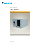
REFRIGERANT CIRCUIT DIAGRAM
Model: UATYQ 250, 350, 450, 550, 600 & 700
No Item Description
1
Compressor
Cooling Operation
Heating Operation
4
2
High Pressure Switch
3
Access Valve
4
4 - Ways Valve
5
Filter Drier
6
Electronic Expansion Valve
7
Strainer
8
Accumulator
9
Low Pressure Switch
10
Solenoid Valve
11
Bypass Capillary Tube
12
Indoor Heat Exchanger
13
Outdoor Heat Exchanger
14
Check Valve 1
15
Check Valve 2
16
Compensator
17
Capillary Tube
3
3
13
12
2
9
1
8
10
11
14
17
16
6
5
Note:
7
15
7
(a) UATYQ350, 450, 550, 600 & 700 consists of 2 circuits in the system.
(b) Item no. 15 & 16 are applicable for UATYQ350 only.
(c) Item no. 17 is applicable for UATYQ700 only.
11
IM-5RTBR-0710(0)-EN.indd 11
8/18/10 4:54:31 PM
INSTALLATION MANUAL
This manual provides the procedures of installation to ensure a safe and good standard of operation for the air
conditioner unit.
Special adjustment may be necessary to suit local requirements.
Before using your air conditioner, please read this instruction manual carefully and keep it for future reference.
This appliance is intended to be used by expert or trained users in shops, in light industry and on farms, or for
commercial use by lay persons.
SAFETY PRECAUTIONS
IMPORTANT
Important information
regarding the
refrigerant used
This product contains
fluorinated greenhouse
gases covered by the
Kyoto Protocol. Do not
vent gases into the
atmosphere.
Refrigerant type:
R410A
GWP (1) value:
1975
WARNING
n Installation and maintenance should be performed by qualified persons who are familiar
with local code and regulation, and experienced with this type of appliance.
n All field wiring must be installed in accordance with the national wiring regulation.
n Ensure that the rated voltage of the unit corresponds to that of the name plate before
commencing wiring work according to the wiring diagram.
n The unit must be GROUNDED to prevent possible hazard due to insulation failure.
n All electrical wiring must not touch the refrigerant piping, or any moving parts of the
fan motors.
n Confirm that the unit has been switched OFF before installing or servicing the unit.
n Disconnect from the main power supply before servicing the air conditioner unit.
n DO NOT pull out the power cord when the power is ON. This may cause serious electrical
shocks which may result in fire hazards.
n Keep the air-conditioner units, power cable and transmission wiring, at least 1m from TVs
and radios, to prevent distorted pictures and static. (Depending on the type and source
of the electrical waves, static may be heard even when more than 1m away).
(1)
GWP =
global warming potential
The refrigerant quantity
is indicated on the unit
name plate. Periodical
inspections for
refrigerant leaks may
be required depending
on European or local
legislation. Please
contact your local dealer
for more information.
Disposal Requirement:
Dismantling of the
unit, treatment of the
refrigerant, oil and other
parts must be done in
accordance with the
applicable legislation.
CAUTION
Please take note of the following important points when installing.
n Do not install the unit where leakage of flammable gas may occur.
If gas leaks and accumulates around the unit, it may cause fire ignition.
n Ensure that drainage piping is connected properly.
If the drainage piping is not connected properly, it may cause water leakage.
n Do not overcharge the unit.
This unit is factory pre-charged.
Overcharge will cause over-current or damage to the compressor.
n Ensure that the unit’s panel is closed after service or installation.
Unsecured panels will cause the unit to operate noisily.
n Sharp edges and coil surfaces are potential locations which may cause injury
hazards.
Avoid from being in contact with these places.
n Before turning off the power supply, set the remote controller’s ON/OFF switch to
the “OFF” position to prevent the nuisance tripping of the unit. If this is not done, the
unit’s fans will start turning automatically when power resumes, posing a hazard to
service personnel or the user.
n Do not operate any heating apparatus too close to the air conditioner unit.
n Do not use joined and twisted wires for incoming power supply.
12
IM-5RTBR-0710(0)-EN.indd 12
8/18/10 4:54:31 PM
A
ENGLISH
INSTALLATION OF THE UNIT
Location For Installation
l Install the unit in such way that air discharged by the unit cannot be drawn in again (as in the case of short circuit of
discharge air). Allow sufficient space for maintenance around the unit.
l When two or more units are installed in a location, they must be positioned such that one unit will not be taking the
discharge air from another unit.
l Ensure that there is no obstruction of air flow into or out of the unit. Remove obstacles which block air intake or air
discharge.
l The location must be well ventilated, so that the unit can draw and distribute plenty of air.
l The unit is recommended to install in:– A place capable of bearing the weight of the unit and isolating noise and vibration.
– A place where has adequate drainage.
– A place where the unit will not be buried in snow.
– A place where air inlet and outlet ports are not exposed to strong wind.
– A place where the air discharge and operating sound level will not annoy the neighbours.
– The location where it is not accessible by general public.
ü To install the unit with economizer kit, follow the recommendations given in part (B) (iii) under chapter “OPTIONAL
ACCESSORY” in this manual.
CAUTION
Do not install the unit at altitude over 2000m.
B
Duct Construction
l This unit are equipped with supply and return air openings. Duct connection to the unit should be made with duct
flanges and secured directly to the air openings with flexible duct connectors to avoid normal noise transmission.
l To prevent air leakage, all duct seams should be sealed.
l Ducts in the spaces that not air-conditioned must be insulated.
l Ducts exposed to the outside must be weather proofed.
l Ducts that entering building through the roof, the entering should be sealed with weather stripping to prevent rain,
sand, dust etc., from entering the building.
l Correct size of filter must be installed at the return air duct.
13
IM-5RTBR-0710(0)-EN.indd 13
8/18/10 4:54:32 PM
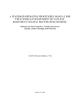
Unit Support (For down throw unit only)
C
l The figure shows the use of the roof curb for mounting
these units.
l The curb should be sealed and fixed to the roof by
weather stripping. A suggested means of sealing the
unit and roof curb as shown in the right.
l Recommended roof curb dimension is shown below.
Unit
Seal with tar
Roof curb
Roof deck
P
Q
SECTION X-X
C
A
D
E
F
G
41.5
I
H
Y
X
Z
Z
J
L
K
B
R
X
Y
M
SECTION Y-Y
25
N
O
52
SECTION Z-Z
Model
(UATYQ)
A
B
C
D
E
F
G
H
I
J
K
L
M
N
O
P
Q
R
250
350/450
550/600/700
355
1506
840
315
315
0
314
0
607
322
540
0
300
141
1784
300
481
1469
355
2081
700
410
410
0
287
131
600
544
682
42
300
141
1908
300
477
1998
355
2081
840
625
462
190
248
131
646
495
676
51
300
141
2365
300
590
1998
Note: All dimensions are in mm
14
IM-5RTBR-0710(0)-EN.indd 14
8/18/10 4:54:32 PM
Unit Lifting
l Holes at 4 corners of the unit base are used for unit
lifting purpose.
l The spreader bar shall be slightly wider than the
unit width.
l The insulation should be added at 4 corners of the
chain to prevent the damage of the panel when
lifting.
ENGLISH
D
Lifting beam
Chain
Spreader
bar
ü Unit shown in diagram is UATYQ250.
ü Other models will follow the same method in lifting.
Drain Piping
B
The drain piping should have a drain trap.
C
l A 1" MPT condensate drain fitting is provided. The
drain pipe can be led out at the front side.
l The drain pipe must be provided with a trap on the
outside of the unit and also installed at an incline
for proper drainage, as shown in the right.
l To prevent condensate formation and leakage,
provide the drain pipe with insulation to safeguard
against sweating.
l Upon completion of piping work, check that there is
no leakage and that the water drains off properly.
A
E
Lifting
holes for
shackle
(4 corners)
A
B
C
≥
≥
≥
70mm
2C
2 X ESP
Drain piping
Drain trap The drain pipe should
extend below this level.
ü ESP = External Static Pressure
Drain trap for condensate
15
IM-5RTBR-0710(0)-EN.indd 15
8/18/10 4:54:33 PM
Space Required Around Unit
F
Electrical control
circuit service
1200
Condenser
air inlet
Condenser
air outlet
3000
Blower & motor
service
1200
Refer diagram below for the space required around the unit. Note that:l All dimensions shown are in mm.
l All space value shown are minimum clearance required for the unit.
l Unit shown in the diagram is UATYQ250. Other models shall follow the same clearance.
Evaporator coil
service
1200
Air filter
service
Compressor service
Electrical control
circuit service
1200
Condenser
air inlet
Condenser
air outlet
3000
Blower & motor
service
1200
Additional space or clearance is required when economizer kit is installed. Whenever the unit is equipped with
economizer kit, the space required around the unit with economizer kit shall follow the diagram below:-
Air filter
service
Evaporator coil
& economizer
kit service
1000
Air filter for economizer
kit service
Compressor service
X : No obstacles and no accumulation of snow or
water shall be allowed in this area.
1200
X
Fresh air
inlet
16
IM-5RTBR-0710(0)-EN.indd 16
8/18/10 4:54:37 PM
ENGLISH
Unit Conversion
G
In the case of converting standard unit to downthrow unit, follow the steps as stated below:
UATYQ250, 350, 450, 550, 600 & 700
1
2
ÑÑÑ
ÇÇÇ
Remove screws
at both sides
Detached
blower
Remove the
Remove the Pulley Belt
side panel
Detached the
blower support
For UATYQ350, 450, 550, 600 & 700
For UATYQ250:
The two side plates are screwed
on the blower support as shown
4
ÉÉÉ
3
The two downflow structure
are screwed to blower
Cover the
horizontal supply
opening with the
blower support
that detached
from the blower
and screw tightly.
Refer Note 2.
Install back the pulley
belt. Adjust the belt
tension by moving the
motor base.
Remove the side
Cover the horizontal
panel at return side
return opening with the
cover and screw tightly. Unscrew the vertical return
Refer Note 2.
cover from the base panel
Turn the blower to face bottom.
Screw at both sides.
Lastly, install back the side panel.
Install back the pulley belt. Adjust the belt tension. Lastly, install back the side panel. Refer Note 1.
For downthrow conversion, belt length need to be changed.
For unit with standard pulley, belt length = a mm
Shaft to shaft distance for downthrow, C-C = b mm
a
b
UATYQ250
1382
375
UATYQ350
1357
388
UATYQ450
1250
375
UATYQ550
1382
445
UATYQ600
1382
445
UATYQ700
1382
435
Sealant such like gasket (field supply) shall be placed in between the metal cover and flange. Besides that, weatherproof silicone shall be applied on all the joints, screw holes and gaps to ensure water-tight condition.
Refer Engineering Data Book for blower curve and technical data of variable pitch pulley.
17
IM-5RTBR-0710(0)-EN.indd 17
8/18/10 4:54:43 PM
PHYSICAL DATA
Heat Pump (R410A)
Model
UATYQ250
UATYQ350
UATYQ450
Refrigerant
UATYQ550
UATYQ600
UATYQ700
R410A
Refrigerant charge
Evaporator air flow
External static pressure
kg
6.1
5.8/5.8
7.2/7.2
8.7/8.7
10.4/10.4
11.6/11.6
CFM
3300
4300
5650
6700
7300
8300
L/S
1557
2029
2667
3162
3445
3917
mmAq
15
21
Pa
147
206
Condenser air flow
CFM
8230
6000/6000
6050/6050
6450/6450
10100/10100
10600/10600
L/S
3884
2831/2831
2855/2855
3044/3044
4767/4767
5003/5003
Scroll/2
Scroll/2
1497 x 495 x 4
1497 x 595 x 4
Control
Wired Rooftop Controller
Control wire length (Standard/Max) : Size
m : mm
2
15 / 100 : 3
Compressor (Type/Quantity)
Scroll/1
Scroll/2
Scroll/2
880 x 467 x 4
1126 x 385 x 4
1126 x 435 x 4
Air filter (Type/Quantity)
Scroll/2
Washable Saranet/2
Air filter dimension (Length x Width x Thickness)
mm
1497 x 392 x 4
ELECTRICAL DATA
Heat Pump (R410A)
UATYQ250
Model
Power supply
UATYQ350
V/Ph/Hz
UATYQ450
UATYQ550
UATYQ600
UATYQ700
380-415/3N~/50
Max continuous current (Comp)
A
26
17/17
19/19
26/26
28/28
29/29
Full load current (FLA, Comp)
A
21
12/12
15/15
21/21
22/22
25/25
Locked rotor current (LRA, Comp)
A
111
74/74
101/101
111/111
118/118
118/118
The equipment fulfils the requirements in EN 61000-3-11 and is subject to conditional connection to the mains. It may
be connected in consultation with the supply authority. The equipment may only be connected to a mains supply with
a system impedance of less than the value stated in table below. The system impedance in the interface point may be
obtained from the supply authority.
Model
Maximum impedance (Zmax), ohm
UATYQ250
0.22
UATYQ350
0.23
UATYQ450
0.21
UATYQ550
0.21
UATYQ600
0.21
UATYQ700
0.21
If the mains supply has a higher system impedance, short voltage dips may appear when the equipment is started or
during operation. This may influence or disturb the operation of other apparatuses, e.g. flickering lamps, especially those
connected to the same supply mains.
18
IM-5RTBR-0710(0)-EN.indd 18
8/18/10 4:54:44 PM
ENGLISH
WIRE CONNECTION
l All electrical work must be carried out by qualified electrician and accordance with local supply requirement and
associate regulation.
Method for connecting electric wire
Before connecting the wire, consult the electric power company of jurisdiction.
1. The entire wiring diagram of unit
a
b PE
c
g
f
d
e
a
Power supply
b
Main switch/fuse
(field supply)
c
Power supply wiring for unit
d
Unit
e
Remote control
f
Connection wiring for unit &
remote controller
g
Earth
2. Wiring connection to unit
Route the power supply wires and control wire through the knockout holes or cable holes in the unit.
Remove the service panels and connect the units power supply wires to terminal block inside the control box, as
shown.
Make use of push releasable cable ties which are located at the bottom of control box to hold the power supply wires
properly.
While installing the circuit breaker onto the unit, make sure that the screws do not damage the components (e.g. coil)
inside the unit.
The switch box also can be installed without attaching to the unit.
The knockout holes are only available in UATYQ250; UATYQ350, UATYQ450, UATYQ550, UATYQ600 & UATYQ700 comes
with a power cable hole.
UATYQ250
UATYQ350, 450, 550, 600 & 700
CONTROL
BOX
Terminal block
CONTROL
BOX
Recommended
switch box position
Power cable (seal off the knockout
holes after installation)
Control wire
Wiring Example And Selection Of Circuit Breaker
Power cable
Breaker
Model
(mm2)
capacity (A)
UATYQ250
4
32
UATYQ350
6
40
UATYQ450
10
40
UATYQ550
10
50
UATYQ600
16
63
UATYQ700
25
80
Power cable
Control wire
Over current
protection switch (A)
32
40
40
50
63
80
Terminal block
Earth cable
(mm2)
4
6
10
10
16
25
A main switch or other means for disconnection, having a contact separation in all poles, must be incorporated in fixed
wiring in accordance with local and national legislation.
ü The unit is to be wired directly from an electrical distribution board either by a circuit breaker (preferred) or HRC fuse.
ü Fix the power supply wiring to control module. Connect control wiring to control terminal block through the control
box’s hole.
ü Earth wiring must be connected.
ü The power supply cord must be equivalent to H07RN-F which is the minimum requirement, and to be used in protective
tube.
ü There must be an all pole disconnection in the supply mains with a contact separation of at least 3mm.
19
IM-5RTBR-0710(0)-EN.indd 19
8/18/10 4:54:45 PM
WARNING
n Before working in this unit, isolate it from the power supply.
n Electrical wiring to this unit and the remote controller shall be installed in accordance with the appropriate requirement of
the local wiring code.
Observe the notes mentioned below when wiring to the terminal
block. Precautions to be taken for power supply wiring.
(Use a round crimp-style terminal for connection to the terminal
block. In case it cannot be used due to unavoidable reasons, be sure
to observe the following instruction.)
Round crimpstyle terminal
Stranded wire
CAUTION
When connecting the connection wires to the terminal block using a single core wire, be sure to perform curling.
Problems with the work may cause heat and fires.
Strip wire end
to this point.
Good
Excessive strip length
may cause electrical
shock or leakage.
Wrong
Stripping wire at terminal block
ü Pull the wire and make sure that it does not disconnect. Then fix the wire in place with a wire stop.
20
IM-5RTBR-0710(0)-EN.indd 20
8/18/10 4:54:46 PM
A
ENGLISH
Arrangement of terminal blocks and components for controller are shown as below:
Control Module UATYQ250
9
1
No. Item Description
5
6
8
2
11
7
10
B
4
1
Controller Main Board
2
EXV Controller Board
3
Capacitor
4
Contactor
5
Phase Protector
6
Relay
7
Terminal Block
8
Fuse
9
Transformer
10
Terminal Block Cover
11
Economizer Controller Board
3
7
Control Module UATYQ350/450/550
6
9
8
5
1
2
7
10
7
4
(Bottom Layer)
C
4
3
11
(Top Layer)
Control Module UATYQ600/700
8
9
5
1
11
6
2
4
7
10
4
7
Item 11 (Economizer Controller Board) shall be used together with the economizer kit which is provided separately as
the accessory.
21
IM-5RTBR-0710(0)-EN.indd 21
8/30/10 8:16:24 AM
OPERATING RANGE
Ensure the operating temperature is within the allowable range, as stated in diagram below:
Cooling
Heating
CAUTION
43
Outdoor WB temperature (°C)
Outdoor DB temperature (°C)
52
50
40
30
20
10
0
-10
10
19 20
14
23
30
Indoor WB temperature (°C)
The use of the air conditioner outside the range
of working temperature and humidity can
result in serious failure.
20
18
10
0
Refer Operating Range for unit with
economizer option in part (E) (vi) in chapter
“OPTIONAL ACCESSORY”.
-10
-15
-20
10
15
20
27
30
Indoor DB temperature (°C)
DB = Dry Bulb
WB = Wet Bulb
CONTROL OPERATION GUIDE
The unit is equipped with a controller main board, and a wired remote controller is connected to the controller main
board.
All the setting in the unit is preset by the manufacturer. It is not recommended to change the setting unless necessary
or mentioned below.
a) Remote Controller Location
The remote controller is located on a metal bracket behind the service panel. It is packed together with installation
manual.
UATYQ250
UATYQ350, 450, 550, 600 & 700
Remove
panel
CONTROL
BOX
CONTROL
BOX
b) LED Display (Controller Main Board)
The LED will blink when power up the unit.
c) LCD Display (Remote Controller)
During normal operations, the LCD displays compressor on/off status, mode, set temperature and so on. Refer to
Operating Manual for the details of operation guide. The LCD will display the main screen upon power-up. When
malfunctioning occur, a pop-up message will appear on the LCD with backlight blinking and ‘beep’ sound.
d) Optional Configurations
The controller main board can be used as the interface for thermostat control and BMS system.
(i) Thermostat control (TB_THM-I)
ü To use this control, set Dip Switch Setting: SW1-ON (default is OFF).
ON
ü Follow the method below for thermostat control inputs:
G
0
1
X
X
X
X
Y1
0
0
1
1
0
0
Y2
0
0
0
1
X
X
W1
0
0
X
X
1
1
W2
0
0
X
X
0
1
Mode
Cool
Cool
Cool
Heatpump/Heater
Heatpump/Heater
Operation
Unit off
Indoor fan on
1 stage compressor
2 stage compressor
1 stage compressor
2 stage compressor
OFF
Remark: X = Don’t care.
22
IM-5RTBR-0710(0)-EN.indd 22
8/30/10 8:16:29 AM
Input
G
Y1
Y2
W1
W2
ENGLISH
ü Refer table below for installation recommendations:
Rated voltage
Rated current
Wire size
24V AC
5mA
AWG18~22
ü When the controller main board is configured as thermostat control, the remote controller is used for monitoring
purpose only.
ü Unit needs to be restarted (power off and on) whenever dip switch setting is changed.
(ii) BMS control (TB_BMS-I)
ü To use this control, set Dip Switch Setting: SW3 - ON (default is OFF) and panel parameter G8 to ‘1’ (default is ‘0’).
ON
ü G8 = Control Type
0 = Panel
1 = BMS
2 = DEC
ü For TB_BMS-I, there are 3 control inputs:
unit on/off ; operating mode (cool-0/heat-1); and set point (4~20mA).
ü Refer below table for installation recommendations:
Input TB_BMS-I
On/Off
Operating mode
Cool/Heat set point
Rated voltage
24V AC
24V AC
-
Rated current
5mA
5mA
4~20mA
OFF
1 2
3 4 5 6
7 8
Wire size
AWG18~22
ü When the controller main board is configured as BMS control, the remote controller is used for monitoring
purpose only.
ü Unit needs to be restarted (power off and on) whenever dip switch setting is changed.
(iii) Dry contact output (TB_BMS-O)
ü For TB_BMS-O, there are 4 monitoring outputs: error alarm; output1; output2; and defrost signal.
ü Refer table below for installation recommendations:
Input TB_BMS-O
Alarm output (AL)
Output1 (O1)
Output2 (O2)
Defrost signal (DFRT)
Rated voltage
230V AC/125V AC/30V DC
230V AC/125V AC/30V DC
230V AC/125V AC/30V DC
230V AC/125V AC/30V DC
Rated current (A)
1/3/3
2/3/3
3/3/3
4/3/3
Wire size
AWG18~22
ü The output signals will vary depending on the configuration of controller main board, whether it is thermostat
control or BMS control.
(1) For thermostat control, the outputs are indicated as shown in the table below.
G
0
1
X
X
X
X
X
X
Thermostat input
(SW1-ON)
Y1
Y2
W1
0
0
0
0
0
0
1
0
X
1
1
X
0
X
1
0
X
1
X
X
X
X
X
X
W2
0
0
X
X
0
1
X
X
ERROR
DEFROST
Alarm output
Output1
Output2
X
X
X
X
X
X
1
X
X
X
X
X
X
X
X
1
(AL)
X
X
X
X
X
X
1
X
(O1)
0
0
1
1
1
1
X
X
(O2)
0
1
0
0
1
1
X
X
Defrost
signal
(DFRT)
X
X
X
X
X
X
X
1
Remark: X = Don’t care.
(2) For BMS control, the outputs are indicated as shown in the table below.
ON/OFF
0
0
1
1
X
X
BMS input
(SW3-ON)
OPERATING
MODE
0
1
0
1
X
X
COOL/HEAT
SET POINT
X
X
X
X
X
X
ERROR
DEFROST
X
X
X
X
1
X
X
X
X
X
X
1
Alarm
output
Output1
Output2
Defrost
signal
(AL)
X
X
X
X
1
X
(O1)
0
0
1
1
X
X
(O2)
0
1
0
1
X
X
(DFRT)
X
X
X
X
X
1
Remark: X = Don’t care.
23
IM-5RTBR-0710(0)-EN.indd 23
8/30/10 8:16:31 AM
The diagram below shows the position for terminal blocks in the controller main board which are used for
thermostat control and BMS system. Beside that, the output pins for auxilliary electrical heater are shown as well.
Thermostat control
inputs
(G, Y1, Y2, W1, W2)
Thermostat Control (TB_THM-l)
Alarm
output
(AL)
Output
1 (O1)
Output
2 (O2)
Defrost
signal
(DFRT)
Supply
Voltage
24V AC
Connect to
third party
controller
Dry Contact Outputs (TB_BMS-O)
Heater Output (HTR1 and HTR2)
Connect to
heater
contactor
Connect to
BMS
System
Connect to
heater
contactor
Unit Cool/ Cool/
on/ Heat Heat
off mode set
select point
BMS System (TB_BMS-l)
Controller Main Board
(iv) Auxilliary Electrical Heater Output (HTR1 and HTR2)
ü There are two output pins (HTR1 and HTR2) on controller main board, which are used to energize the heater
contactor. The contactor must be selected accordingly to avoid any safety issue(s).
ü The heater shall be installed in accordance with local and national legislation. It must comply with EN60335-2-40.
ü Thermal fuse(s) shall be installed on the heater to eliminate any danger or damage on the heater/unit. This is
especially critical when there is any malfunction happen to controller main board or blower.
ü The heater shall be in a safe location, whereby no risk of damage could be happen on the unit.
ü Use non-flammable duct for the unit that is installed with heater
ü Use different power supply for electrical heater and install a circuit breaker for each of the heater.
ü Maximum temperature in the unit must not exceed 60°C. Temperature measurement shall be taken during the
installation or commisioning in order to ensure the temperature not exceed this value.
ü Select the proper safety device or thermal protector accordingly.
ü The heater shall never be installed inside the unit. The recommended location for the heater is inside the supply
duct, whereby the distance of the heater is sufficient to ensure the temperature inside the unit does not exceed
60°C.
(v) Economizer control
ü Ensure the economizer kit has been incorporated with rooftop unit before activate the economizer function in
the controller main board. Else, error will occur.
ü To activate economizer function, set Dip Switch Setting: SW4 - ON (default is OFF) in the controller main board
and panel parameter G6 to ‘1’ (default is ‘0’).
ON
G6 = Economizer control
OFF
0 = disable
1 2 3 4 5 6 7 8
1 = enable.
ü In economizer controller board, there are 4 dip switches and 3 shunt jumpers which provide flexible selection
based on different requirements:
– Dip Switch 1: Minimum fresh air opening setting in heating mode, where by the selection of different pins will
give different opening setting. SW1: 5%, SW2: 10%, SW3: 15%, SW4: 20%, SW5: 25%, SW6/7/8:
no function, Default: 0% (no selection, all OFF).
– Dip Switch 2: Minimum fresh air opening setting in cooling mode, where by the selection of different pins will
give different opening setting. SW1: 0%, SW2: 5%, SW3: 15%, SW4: 20%, SW5: 25%, SW6/7/8:
no function, Default: 10% (no selection, all OFF).
– Dip Switch 3: CO2 PPM level threshold value selection, where by the selection of different pins will give
different value setting. SW1: 25%, SW2: 50%, SW3: 75%, SW4: 100%, Default: 0% (no selection,
all OFF).
– Dip Switch 4: Type of operation, which include the following selection:SW1: OFF = Differential temperature operation (default), ON = No function at this moment.
SW2: OFF = Economizer mode (default), ON = Fresh air mode.
SW3: OFF = Overcooled protection is not activated (default), ON = Overcooled protection is
activated.
24
IM-5RTBR-0710(0)-EN.indd 24
8/30/10 8:16:31 AM
Fresh air opening (%)
0 (default)
10
20
30
40
50
70
85
JP1
OFF
OFF
OFF
OFF
ON
ON
ON
ON
JP2
OFF
OFF
ON
ON
OFF
OFF
ON
ON
ENGLISH
Shunt jumper 1, 2 and 3: Minimum fresh air opening setting in fan mode, where by the selection of different
pins will give different opening setting. Let name the shunt jumper 1 = JP1, shunt jumper 2 = JP2 and shunt
jumper 3 = JP3; refer the table below for different fresh air opening selection:JP3
OFF
ON
OFF
ON
OFF
ON
OFF
ON
Legend: OFF = Short pin 2 and pin 3
ON = Short pin 1 and pin 2
CAUTION
Dip Switch 1, 2 and 3 allow only 1 pin selection. Multiple pins selection will cause error and the operation will go back to
default setting. While Dip Switch 4 allow multiple pins selection.
Location of dip switches and shunt jumpers
in the economizer controller board:
Shunt jumper 2
Indication on the economizer controller board:
Indication for the means of selection for shunt
jumper 1, 2 and 3.
Shunt jumper 3
Shunt jumper 1
Dip Switch 3
Dip Switch 1
Dip Switch 2
Indication for the
means of selection
for Dip Switch 1.
Indication for the
means of selection
for Dip Switch 3.
Indication for the
means of selection
for Dip Switch 2.
Indication for the
means of selection
for Dip Switch 4.
Dip Switch 4
ü There are two LEDs in economizer controller board, which are green LED and red LED. Green LED will blink when
economizer controller board is powered-up. Red LED will blink when error(s) occur. Refer the table below for
error codes and their meaning:Error
Code
F0
F1
F2
F3
F4
F5
F6
F7
F8
F9
FA
Fault
Fresh air actuator faulty/ malfunction
Return air actuator faulty/ malfunction
Communication error
CO2 sensor short
CO2 sensor open
Fresh air RH sensor short
Fresh air RH sensor open
Return air RH sensor short
Return air RH sensor open
Activation of actuator protection
Multiple pins selection in Dip Switch 1, 2 or 3
The error codes will be shown on the seven segment
display on the economizer controller board.
Seven segment display
When error(s) occur and the faults persist, please call your authorized local dealer/ serviceman for
troubleshooting. However, all the errors occur in economizer controller board will not affect the normal
operation of rooftop unit.
25
IM-5RTBR-0710(0)-EN.indd 25
8/30/10 8:16:32 AM
SERVICE AND MAINTENANCE
SERVICE OF THE FILTER
ü Remove any dust adhering to the filter by using a vacuum cleaner or wash in lukewarm water (below 40°C) with neutral
cleaning detergent.
ü Rinse the filter well and dry before placing it back onto the unit.
ü Do not use gasoline, volatite substances or chemicals to clean the filter.
ü Clean the filter at least once every 2 weeks. Or more frequently if necessary.
Filter Position
The filters are mounted in front of the indoor heat exchanger.
Unit shown in the diagram is UATYQ250. Other models shall follow the same method.
Remove filter cover for filter service.
Alternatively, remove side panel for filter service.
For unit which is installed together with economizer kit, there is one additional filter which is mounted at the bottom
side of rain hood. Unit shown in the diagram is UATYQ250 + economizer kit (field installed). Other models shall follow
the same method.
Rain hood (field installed)
Remove filter cover on the rain hood for filter
service.
CAUTION
Ensure the filter is placed properly and the filter cover is
fastened with screws tightly after the service to avoid water
leaking. If necessary, weather-proof sealant shall be applied
in order to ensure water-proof finishing on the filter cover
and rain hood.
VACUUMING AND CHARGING
The rooftop package units are factory pre-charged with sufficient refrigerant. However, there may be a need for
charge recovery during service and maintenance works. Therefore, some precautions must be taken to ensure
optimum and trouble-free system operation:
(i) The system should be throughly vacuumed to ensure no incompressible gas and moisture in the system.
(ii) Use a vacuum pump for R410A exclusively. Using the same vacuum pump for different refrigerants may damage
the vacuum pump or the unit.
(iii) The refrigerant should never be released directly into the environment.
(iv) When charging R410A, ensure that only liquid is being withdrawn from the cylinder or can.
Dip-pipe
Invert cylinder
without dip-pipe
Liquid
withdrawal
26
IM-5RTBR-0710(0)-EN.indd 26
8/30/10 8:16:33 AM
CAUTION
ENGLISH
Normally, the R410A cylinder or can is being equipped with a dip-pipe for liquid withdrawal. However, if the dippipe is not available, invert the cylinder or can so as to withdraw liquid from the valve at the bottom.
n R410A must be charged as liquid. Usually R410A cylinder is equipped with a dip-pipe for liquid withdrawal. If there is no dippipe, the cylinder should be inverted so as to withdraw liquid R410A from the valve.
n Do not top-up when servicing leak, as this will reduce the unit performance. Vacuum the unit thoroughly and then charge the
unit with fresh R410A according to the amount recommended in the specification.
TROUBLESHOOTING
For any enquiries on spare part please contact your authorized dealer. If any malfunction of the air-conditioner
unit is noted, check the following fault conditions and causes for some simple troubleshooting tips.
Problem
Unit does not run.
Causes
l Power failure.
l Fuse blown or circuit breaker
tripped.
l Power supply wiring phase incorrect.
Action
l Press the [ON/OFF] after
power restore.
l Replace fuse or reset
circuit breaker.
l Modify the wiring phase.
Compressor does not
operate in 3 min after
unit has started.
l Protection against frequent starting.
l Wait for 3 min for the
compressor to start.
Air flow is low.
l Filter is filled with dust and dirt.
l There are some obstacles at the air
inlet or outlet of the units.
l Clean the filter.
l Remove obstacles.
Compressor operate
continuously.
l Dirty air filter.
l Temperature setting is too low (for
cooling).
l Temperature setting is too high (for
heating).
l Clean the air filter.
No cool air delivered
during cooling cycle,
or no hot air delivered
during heating cycle.
l Temperature setting is too high (for
cooling).
l Temperature setting is too low (for
heating).
l Set the temperature
lower.
l Set the temperature
higher.
On heating cycle, no air
delivered (UATYQ250).
Or, the delivered air
is not warm enough
(UATYQ350/450/550/
600/700).
l Unit is in defrosting cycle.
l Wait for a while.
(It will be resumed after
defrosting.)
l Reset the temperature.
If the fault persists, please call your authorized local dealer/serviceman.
27
IM-5RTBR-0710(0)-EN.indd 27
8/17/10 2:26:04 PM
OPTIONAL ACCESSORY
ECONOMIZER KIT
A
Introduction
Economizer kit is an accessory provided by the factory, but requires field installation. Economizer kit is compatible for R410A
rooftop models. If you are unsure whether this kit can be used with your particular unit, please contact authorized service
division. The economizer kit allows outside air to be mixed with return air for ‘free’ cooling if the outdoor air temperature is
suitable. Economizer cooling can be used alone or in conjunction with mechanical cooling. Beside that, the economizer
kit can be used as well to provide ventilation air thus can improve indoor air quality. It is vital to do a correct selection on
economizer kit, refer the table below for kit selection guideline:
No.
Rooftop Unit
1
2
3
4
5
6
UATYQ250
UATYQ350
UATYQ450
UATYQ550
UATYQ600
UATYQ700
Economizer kit which is compatible with
rooftop unit
ECONO250
ECONO350
ECONO450
ECONO550
ECONO600
ECONO700
Wrong selection may cause the kit is unable to be assembled with the rooftop unit.
B
(i)
Preinstallation Checking
The Contents of Economizer Kit
Before installation, it is recommended to check the contents of the economizer kit after removing the packaging.
The kit includes the following components:
No.
1
2
3
4
5
6
7
Item Description
Belimo actuator, LF24-SR
Side panel with outdoor air damper
Hood, top panel
Hood, center panel
Hood, bottom panel
Hood, side panel left
Hood, side panel right
Quantity
(set)
2
1
1
1
1
1
1
No.
8
9
10
11
12
13
14
Item Description
Filter cover
Filter
Support bracket, return air damper
Return air damper
Support bracket, down throw
Screw, M5x16
Screw, M4x12
Quantity
(set)
1
1
1
1
1
55
4
Contact authorized service division if accessory is damaged or incomplete.
(ii)
Unit Clearance
Provide sufficient space for air flow, servicing and wiring after the kit is mounted on the unit. There shall be no
obstruction of air flow in this space. Refer to part (F) under chapter “INSTALLATION OF THE UNIT” in this manual. Fail
to do so may cause low air flow or unit malfunction.
28
IM-5RTBR-0710(0)-EN.indd 28
8/30/10 8:16:34 AM
Location for installation
Follow the recommendations given in part (A) under chapter “INSTALLATION OF THE UNIT” in this manual. In
addition, there is a need to consider the installation condition around the kit whereby:
ü The clearance of the rain hood from the floor shall always have no snow nor water accumulation.
ü The fresh air inlet does not face prevailing wind direction.
ü The outdoor air shall be always clean and no odor, complies with the limit of concentration for several
contaminants set by local standards, and does not exceed the threshold limit value (TLV) for toxicity specified
by local standards.
(iv)
Damper Function
Check the two dampers in the economizer kit, which are item 2 and item 11 by turning the shaft of damper +90°
and -90° (fully opened to fully closed or vice versa). The damper turning shall be smooth and easy. Any damages
or abnormalities shall inform to authorized service division.
C
(i)
(ii)
(iii)
(iv)
(v)
(vi)
D
(i)
ENGLISH
(iii)
Tools And Materials Required For Installation
Electric screwdriver with assorted sockets
Electric driller with assorted sockets
Small flat blade screwdriver
Cutter
Philip type screwdriver
Measurement tape or ruler
(vii)
(viii)
(ix)
(x)
(xi)
(xii)
Adjustable spanner (small size)
Crowbar and hammer
Weather-proof sealant (such as silicone)
Gasket
Safety lockout tag
Cable tie
Installation Guidelines
Side return (horizontal) application
STEP 1
– Disconnect power supply to the unit and install a safety lockout tag before installation, commisioning or service
of the economizer unit. Prepare all the tools required as mentioned above.
STEP 2
- Unpack the wooden crate of economizer kit by using crowbar and hammer. Then, remove the polybags containing
loose parts and fasteners by using cutter. Perform preinstallation checking as mentioned above.
STEP 3
- Attach support bracket, return air damper (item 10) to return air damper (item 11) by using screw M5x16 (item
13) provided in the kit.
Screw item 10 to
item 11
Item 11
Item 10
STEP 4
- Mount 1pc Belimo actuator, LF24-SR (item 1) labelled with ‘RA’ to return air damper (item 11). Align and insert
the hole of actuator to the shaft of the damper.
CAUTION 1
The default setting for return air damper (item 11) shall be fully opened. Ensure this damper is in ‘fully opened’ position
before mounting it to the actuator. Failed to do so will cause errors during the unit operation.
CAUTION 2
The surface of actuator which is facing upward/ outside shall be labelled with ‘L’ symbol to ensure the rotation of actuator
modulation in clockwise direction. Failed to do so will cause errors during the operation of unit with economizer
function.
29
IM-5RTBR-0710(0)-EN.indd 29
8/30/10 8:16:36 AM
There are 2pcs of Belimo actuator, LF24-SR (item 1) in economizer kit which come together with carton boxes.
Open the boxes and recognize the label on the wire. The actuator used in step 4 is the one with label ‘RA’.
OR
2pcs of item 1 in
carton boxes.
-
Recognize the label on the wire. One of them
is indicated with ‘RA’, while the other is ‘OA’.
Then, fastens 1pc screw M4x12 (item 14) on the support bracket of the damper. Do not fully insert the screw
thread, but only insert up to 2/3 of the screw thread. Mount the actuator to the support bracket by bringing the
support bracket closer to the shaft of damper. The function of screw M4x12 is to lock the actuator from slipperry
during modulation.
Next, put the clamp into the shaft and lock the actuator with circlip. Fasten the nuts of clamp tightly by using
adjustable spanner. Noted that clamp and circlip come together with actuator as the standard parts, you may
find these parts inside the actuator box.
Circlip
2pcs of Nuts
(screw tightly)
Labelled
with 'L'
symbol
Clamp
Details view for clamp
and circlip
Circlip
Clamp
Item 1 (with label 'RA')
Item 10 and item 11,
which are already
assembled in Step 3.
Top view for damper
12
110
Ø3
45
b) Insert screw
M4x12, then bring
the support bracket
closer to the shaft
of damper. Note:
support bracket is
located on the top
of damper.
12
a) Mount the actuator
to the shaft of damper,
then lock with circlip and
clamp.
Detail view for actuator
90
-
Open the box.
Support bracket 150
Fasten M4x16 screw on this hole, do
not fully insert the screw thread, but
insert only 2/3 of the thread.
STEP 5
- Remove side panel. Then, detach 4pcs metal bracket on front panel. Install the return air damper (item 11) +
support bracket, return air damper (item 10) + Belimo actuator, LF24-SR (item 1) which are already assembled
in step 3 and step 4 into front panel of the unit by using the same screw holes. Use screw M5x16 (item 13) for
fastening purpose.
CAUTION
Extend the return air sensor which is located inside the unit (on top of return air opening) to the outside area of the unit.
This can be done by routing the sensor through small holes on support bracket, return air damper (item 10). The sensor
is then located properly inside the return air duct by using the cable ties (field supply). Failing to do so may affect the
performance of the unit and cause thermal discomfort to the users.
Detach metal brackets
on front panel.
Front panel of
the unit
Item 1
Remove side panel
Item 10 +
item 11
Use any three holes below on item 10 to route
the return air sensor to the outside of the unit.
Front panel of
the unit
Mount item 1+ item10 +
item 11 into front panel.
Front view of item 10
30
IM-5RTBR-0710(0)-EN.indd 30
8/30/10 8:16:36 AM
ENGLISH
STEP 6
- Mount 1pc Belimo actuator, LF24-SR (item 1) labelled with ‘OA’ to the side panel with outdoor air damper (item
2). Align and insert the hole of actuator to the shaft of the damper.
CAUTION 1
The default setting for outdoor air damper (item 2) shall be fully closed. Ensure this damper is in ‘fully closed’ position
before mount the actuator. Fail to do so will cause errors during the unit normal operation.
CAUTION 2
The surface of actuator which is facing upward/ outside shall be labelled with ‘R’ symbol to ensure the rotation of actuator
modulation in counter clockwise direction. Fail to do so will cause errors during the operation of unit with economizer
function.
There are 2pcs of Belimo actuator, LF24-SR (item 1) in economizer kit which come together with carton boxes.
Open the boxes and recognize the label on the wire. The actuator used in step 6 is the one with label ‘OA’.
OR
2pcs of item 1 in
carton boxes.
-
Recognize the label on the wire. One of them
is indicated with ‘RA’, while the other is ‘OA’.
Then, fastens 1pc screw M4x12 (item 14) on the support bracket of the damper. Do not fully insert the screw
thread, but only insert up to 2/3 of the screw thread. Mount the actuator to the support bracket by bringing the
support bracket closer to the shaft of damper. The function of screw M4x12 is to lock the actuator from slipperry
during modulation.
Next, put the clamp into the shaft and lock the actuator with circlip. Fasten the nuts of clamp tightly by using
adjustable spanner. Noted that clamp and circlip come together with actuator as the standard parts, you may
find these parts inside the actuator box.
Circlip
2pcs of Nuts
(screw tightly)
Labelled
with ‘R’
symbol
Clamp
b) Insert screw
M4x12, then bring
the support bracket
closer to the shaft
of damper. Note:
support bracket is
located on the top of
damper.
Item 2
Detail view for actuator
Item 1 (with label ‘OA’)
Top view for damper
12
110
Ø3
90
Circlip
Clamp
a) Mount the actuator
to the shaft of damper,
then lock with circlip and
clamp.
12
Details view for clamp
and circlip
150
45
-
Open the box.
Support bracket
Fasten M4x16 screw on this hole, do
not fully insert the screw thread, but
insert only 2/3 of the thread.
31
IM-5RTBR-0710(0)-EN.indd 31
8/30/10 8:16:41 AM
STEP 7
- Connect Belimo actuator, LF24-SR (item 1) with label ‘RA’, which is now located at the assembly damper on the
front panel to terminal block with label ‘RA’ inside the junction box.
- There are four wires on the actuator with different colours (black, red, green and white colours). Connect the
wires as below:
Black colour wire - connect to first pole of
terminal block with label ‘GND’.
Red colour wire - connect to second pole of
terminal block with label
Sticker wiring
‘+24V’.
diagram on
Green colour wire - connect to third pole of
the front cover
terminal block with label ‘DCV’.
of junction
White colour wire - connect to fourth pole of
box
terminal block with label ‘FB’.
(You may refer to sticker wiring diagram which is
located on the front cover of junction box.)
TB RA
FB
RED
BLACK
WHITE
RED
GREEN
BLACK
TB OD
GND +24V DCV
WHITE
TO PCB3 (ECO)
CN_C02
TO PCB3 (ECO)
CN_ACT_OD
WHITE
RED
GREEN
BLACK
TO PCB3 (ECO)
CN_ACT_RA
TB C02
GND +24V DCV
ACTUATOR RA
FB
GND +24V
ACTUATOR OD
FB
C02 SENSOR
CAUTION
Wrong wiring connection may cause the malfunction on actuator or economizer controller board or both. Tie the wires
with releasable cable ties under the junction box.
-
Then, connect Belimo actuator, LF24-SR (item 1) with label ‘OA’, which is now located at the assembly damper
on the side panel to terminal block with label ‘OA’ inside the same junction box. Follow the same method used
for wiring connection between actuator ‘RA’ and terminal block ‘RA’. Next, attach the side panel to the unit. You
may need to do proper arrangement on the actuator wires by using cable ties (field supply) before attach the
side panel to the unit.
Label ‘RA’
Label ‘OA’
Terminal
block with
label ‘RA’
- to be
connected
with
actuator
with label
‘RA’.
Junction
box
Terminal block with label ‘OA’ - to be
connected with actuator with label ‘OA’.
Side panel in standard
unit which is removed in
step 5.
Side panel comes with
economizer kit which is
assembled with actuator in step
6. Attach this panel to the unit.
Detail view of junction box
STEP 8
- To build the rain hood, install the loose parts (metal parts) to the side panel. Before that, place the gasket (field
supply) on the side panel for sealing purpose.
- Then, follow the installation sequence below to build the rain hood:
Gasket
Item 2
Item 6
Item 7
Item 3
Side panel with outdoor
air damper (item 2) which
is assembled to the unit
in step 7.
Item 4
Item 5
Item 9
Item 8
Sealant
Item 3
Item 7
Item 4
Item 5
Item 9
Item 6
Item 8
-
It is recommended to seal off all the joints and gaps with weather-proof sealant (such as silicone, field supplied
item) in order to ensure a water-proof finishing on the rain hood.
32
IM-5RTBR-0710(0)-EN.indd 32
8/30/10 8:16:43 AM
ENGLISH
STEP 9
- Finally, you may see the unit with economizer kit as shown in the diagram below:
Rooftop
unit
Rain hood
Return air
damper
Unit shown in the diagrams from step 1 to step 9 are UATYQ350. Other models shall follow the same method.
(ii)
Down return (vertical) application
STEP 1
- Disconnect power supply to the unit and install a safety lockout tag before installation, commisioning or service
of the economizer unit. Prepare all the tools required as mentioned above.
STEP 2
- Unpack the wooden crate of economizer kit by using crowbar and hammer. Then, remove the polybags containing
loose parts and fasteners by using cutter. Perform preinstallation checking as mentioned above.
STEP 3
- Attach support bracket, down throw (item 12) to return air damper (item 11) by using screw M5x16 (item 13)
provided in the kit.
Screw item 12
to item 11.
Item 12
Item 11
STEP 4
- Mount 1pc Belimo actuator, LF24-SR (item 1) to return air damper (item 11). Align and insert the hole of actuator
to the shaft of the damper.
CAUTION 1
The default setting for return air damper (item 11) shall be fully opened. Ensure this damper is in ‘fully opened’ position
before mount the actuator. Fail to do so will cause errors during the unit normal operation.
33
IM-5RTBR-0710(0)-EN.indd 33
8/30/10 8:16:44 AM
CAUTION 2
The surface of actuator which is facing upward/ outside shall be labelled with ‘L’ symbol to ensure the rotation of
actuator modulation in clockwise direction. Fail to do so will cause errors during the operation of unit with economizer
function.
There are 2pcs of Belimo actuator, LF24-SR (item 1) in economizer kit which come together with carton boxes.
Open the boxes and recognize the label on the wire. The actuator used in step 4 is the one with label ‘RA’.
OR
2pcs of item 1 in
carton boxes.
Then, fastens 1pc screw M4x12 (item 14) on the support bracket of the damper. Do not fully insert the screw
thread, but only insert up to 2/3 of the screw thread. Mount the actuator to the support bracket by bringing the
support bracket closer to the shaft of damper. The function of screw M4x12 is to lock the actuator from slipperry
during modulation.
Next, put the clamp into the shaft and lock the actuator with circlip. Fasten the nuts of clamp tightly by using
adjustable spanner. Noted that clamp and circlip come together with actuator as the standard parts, you may
find these parts inside the actuator box.
Clamp
2pcs of Nuts
(screw tightly)
Labelled
with ‘L’
symbol
Details view for clamp
and circlip
Detail view for actuator
Circlip
Clamp
a) Mount the actuator
to the shaft of damper,
then lock with circlip and
clamp.
Item 11 and item 12,
which are already
assembled in step 3.
Item 1 (with label ‘RA’)
b) Insert screw
M4x12, then bring
the support bracket
closer to the shaft
of damper. Note:
support bracket is
located on the top of
damper.
Top view for damper
12
110
Ø3
90
Circlip
45
-
Recognize the label on the wire. One of them
is indicated with ‘RA’, while the other is ‘OA’.
12
-
Open the box.
150
Support bracket
Fasten M4x16 screw on this hole, do not
fully insert the screw thread, but insert
only 2/3 of the thread.
STEP 5
- Remove side panel. Conduct unit conversion from standard unit to downthrow unit by following the steps stated
in part (G) under chapter “INSTALLATION OF THE UNIT” in this manual.
- Then, install the return air damper (item 11) + support bracket, down throw (item 12) + Belimo actuator, LF24SR (item 1) which are already assembled in step 3 and step 4 into indoor base panel of the unit by using screw
M5x16 (item 13).
CAUTION
Extend the return air sensor which is located inside the unit (on top of return air opening) to the outside area of the
unit. This can be done by routing the sensor through small holes on support bracket, down throw (item 12). The sensor
is then located properly inside the return air duct by using the cable ties (field supply). Failing to do so may affect the
performance of the unit and cause thermal discomfort to the users.
34
IM-5RTBR-0710(0)-EN.indd 34
8/30/10 8:16:46 AM
Mount item 1+ item11 +
item 12 into indoor base
panel.
Item 11
Item 1
ENGLISH
Conduct unit conversion.
Then, mount item 1+ item 11 + item 12 into indoor base panel as shown below:
Item 12
Remove side
panel
Use any three holes below on item 12 to route
the return air sensor to the outside of the unit.
Indoor base panel
of the unit
Front view of item 12
STEP 6
- Mount 1pc Belimo actuator, LF24-SR (item 1) to the side panel with outdoor air damper (item 2). Align and insert
the hole of actuator to the shaft of the damper.
CAUTION 1
The default setting for outdoor air damper (item 2) shall be fully closed. Ensure this damper is in ‘fully closed’ position
before mount the actuator. Fail to do so will cause errors during the unit normal operation.
CAUTION 2
The surface of actuator which is facing upward/ outside shall be labelled with ‘R’ symbol to ensure the rotation of actuator
modulation in counter clockwise direction. Fail to do so will cause errors during the operation of unit with economizer
function.
There are 2pcs of Belimo actuator, LF24-SR (item 1) in economizer kit which come together with carton boxes.
Open the boxes and recognize the label on the wire. The actuator used in step 6 is the one with label ‘OA’.
OR
2pcs of item 1 in
carton boxes.
-
-
Open the box.
Recognize the label on the wire. One of them
is indicated with ‘RA’, while the other is ‘OA’.
Then, fastens 1pc screw M4x12 (item 14) on the support bracket of the damper. Do not fully insert the screw
thread, but only insert up to 2/3 of the screw thread. Mount the actuator to the support bracket by bringing the
support bracket closer to the shaft of damper. The function of screw M4x12 is to lock the actuator from slipperry
during modulation.
Next, put the clamp into the shaft and lock the actuator with circlip. Fasten the nuts of clamp tightly by using
adjustable spanner. Noted that clamp and circlip come together with actuator as the standard parts, you may
find these parts inside the actuator box.
35
IM-5RTBR-0710(0)-EN.indd 35
8/30/10 8:16:47 AM
Clamp
2pcs of Nuts
(screw tightly)
Details view for clamp
and circlip
Labelled
with ‘R’
symbol
Detail view for actuator
Circlip
Clamp
a) Mount the actuator
to the shaft of damper,
then lock with circlip and
clamp.
Item 1 (with label ‘OA’)
Top view for damper
12
110
Ø3
12
b) Insert screw
M4x12, then bring
the support bracket
closer to the shaft
of damper. Note:
support bracket is
located on the top of
damper.
Item 2
45
90
Circlip
150
Support bracket
Fasten M4x16 screw on this hole, do
not fully insert the screw thread, but
insert only 2/3 of the thread.
STEP 7
- Connect Belimo actuator, LF24-SR (item 1) with label ‘RA’, which is now located at the assembly damper on the
indoor base panel to terminal block with label ‘RA’ inside the junction box.
- There are four wires on the actuator with different colours (black, red, green and white colours). Connect the
wires as below:
Black colour wire - connect to first pole of
terminal block with label ‘GND’.
Red colour wire - connect to second pole of
terminal block with label
Sticker wiring
‘+24V’.
diagram on
Green colour wire - connect to third pole of
the front cover
terminal block with label ‘DCV’.
of junction
White colour wire - connect to fourth pole of
box
terminal block with label ‘FB’.
(You may refer to sticker wiring diagram which is
located on the front cover of junction box.)
TB RA
FB
ACTUATOR RA
RED
BLACK
WHITE
RED
GREEN
BLACK
TB OD
GND +24V DCV
WHITE
TO PCB3 (ECO)
CN_C02
TO PCB3 (ECO)
CN_ACT_OD
WHITE
RED
GREEN
BLACK
TO PCB3 (ECO)
CN_ACT_RA
TB C02
GND +24V DCV
FB
ACTUATOR OD
GND +24V
FB
C02 SENSOR
CAUTION
Wrong wiring connection may cause the malfunction on actuator or economizer controller board or both. Tie the wires
with releasable cable ties under the junction box.
-
Then, connect Belimo actuator, LF24-SR (item 1) with label ‘OA’, which is now located at the assembly damper
on the side panel to terminal block with label ‘OA’ inside the same junction box. Follow the same method used
for wiring connection between actuator ‘RA’ and terminal block ‘RA’. Next, attach the side panel to the unit. You
may need to do proper arrangement on the actuator wires by using cable ties (field supply) before attach the
side panel to the unit.
Label ‘RA’
Junction
box
Label ‘OA’
Terminal
block with
label ‘RA’
- to be
connected
with actuator
with label
‘RA’
Terminal block with label ‘OA’ - to be
connected with actuator with label ‘OA’.
Side panel comes with
Side panel in standard
unit which is removed in economizer kit box which is
assembled with actuator in
step 5.
step 6. Attach this panel to
the unit.
Detail view of junction box
36
IM-5RTBR-0710(0)-EN.indd 36
8/30/10 8:16:52 AM
ENGLISH
STEP 8
- To build the rain hood, install the loose parts (metal parts) to the side panel. Before that, place the gasket (field
supply) on the side panel for sealing purpose.
- Then, follow the installation sequence below to build the rain hood:
Gasket
Item 2
Item 6
Item 7
Item 3
Item 4
Item 5
Item 9
Item 8
Sealant
Item 3
Side panel with outdoor
air damper (item 2) which
is assembled to the unit
in step 7.
Item 7
Item 4
Item 5
Item 9
Item 6
Item 8
-
It is recommended to seal off all the joints and gaps with weather-proof sealant (such as silicone, field supplied
item) in order to ensure a water-proof finishing on the rain hood.
STEP 9
- Finally, you may see the unit with economizer kit as shown in the diagram below:
- When roof curb is required for down throw application, refer to the recommendation in part (C) under chapter
“INSTALLATION OF THE UNIT” in this manual.
Metal cover
(blower
support) for
horizontal
return
Rooftop
unit
Rain hood
Metal cover for
horizontal return
Unit shown in the diagrams from step 1 to step 9 are UATYQ350. Other models shall follow the same method.
37
IM-5RTBR-0710(0)-EN.indd 37
8/30/10 8:16:53 AM
E
Commissioning
(i)
Airflow Resistance
Airflow resistance refers to pressure drop caused by the economizer kit. Before installation, it is recommended to check
the pressure drop table which is provided in Engineering Data Book in order to do a correct design selection.
(ii) Performance Adjustment
Performance of the unit will derate when the unit operates with fresh air mode, it depends on user’s selection. Before
installation, it is recommended to check the correction factor table which is provided in Engineering Data Book in
order to do a correct design selection.
(iii) Mode Selection
Generally, the kit provides two mode selection, which are Economizer Mode and Fresh Air Mode.
- Economizer Mode: Provide ‘free’ cooling when the outdoor air temperature is suitable. It can used alone or in
conjunction with mechanical cooling.
- Fresh Air Mode: Provide minimum fresh air that is necessary for ventilation or local requirements.
Refer to hardware setting guideline provided in part (D) (v) under chapter “CONTROL OPERATION GUIDE” in this
manual for mode selection.
(iv) Minimum Fresh Air Selection
The kit provides minimum fresh air selection from 0~25% for both cool and heat mode. While the economizer mode
& fan mode can provide up to maximum 85% of fresh air.
(v)
Refer to hardware setting guideline provided in part (D) (v) under chapter “CONTROL OPERATION GUIDE” in this
manual for minimum fresh air selection.
Overcooled Protection Feature
Thermal discomfort may happen during the cold ambient due to the outdoor air damper opening. This situation
can be avoided when the overcooled protection feature is activated.
Refer to hardware setting guideline provided in part (D) (v) under chapter “CONTROL OPERATION GUIDE” in this
manual for the activation of overcooled protection setting.
(vi) Operating Range
The applicable operating range for unit with economizer feature same like normal unit. Refer to chapter “OPERATING
RANGE” in this manual.
However, the restriction of fresh air opening will occur in high ambient or low ambient in order to ensure the reliability
of the unit. Refer to Engineering Data Book for detail information.
CAUTION
The performance will be reduced at high ambient or low ambient, refer item (E)(ii).
(vii) Optional Air Filter
There is a 2" filter slot inside the unit. Optional filter (field supplied) is recommended as the second layer filtration
since outdoor air damper opening may bring in dust and dirt.
F
Service And Maintenance
(i)
Service of the filter
Airflow resistance may increase when the filter becomes dirty. Thus, clean the filter regularly with at least once
every 2 weeks. Air filter in rain hood which is exposed to outdoor environment may have chance to be damaged by
vermins or animals. Replace the air filter when it is damaged.
(ii) Service of the indoor compartment
Outdoor air damper opening may still bring in dust and dirt as hood filter cannot fully filter the dirt particles. Thus,
indoor compartment must be cleaned as well during the service of filter.
(iii) Service of the damper
Wipe the dirty damper, especially outdoor air damper which is exposed to the environment all the time.
Refer to chapter “SERVICE AND MAINTENANCE” in this manual.
38
IM-5RTBR-0710(0)-EN.indd 38
8/30/10 8:16:55 AM
Demand Ventilation Control
- One technique to reduce energy consumption while maintain adequate air quality is demand controlled ventilation.
Instead of setting at a fixed air replacement rate, carbon dioxide sensor (CO2 sensor) is used to control the rate
dynamically, based on the emissions of actual building occupants.
- CO2 sensor is an optional component supplied in field. Refer to the information below for the recommendation of CO2
sensor selection:
(i)
Type: Duct-mounted type
(ii) Power input: 24 VDC, 50Hz
(iii) Operating temperature range: 0 ~ 52°C
(iv) Ambient temperature range: -15 ~ 52ºC
(v) Measuring range: 0 ~ 5000 PPM (depends on the application)
(vi) Output voltage: 2 ~ 10 VDC
(vii) Wire size: AWG18
(viii) Maximum allowable current: 7A
(ix) Compliance standards: To follow local and national regulations
- The economizer controller comes with a build-in software which is ready with the integration of CO2 sensor. It is activated
only in economizer mode. User is allowed to choose the different threshold value selection via Dip switch 3. Refer to
hardware setting guideline provided in part (D) (v) under chapter “CONTROL OPERATION GUIDE” in this manual for CO2
PPM level threshold value selection.
For example: To use a CO2 sensor with measuring range from 0 ~ 5000 PPM with the threshold value at 1250PPM, user
needs to do the following steps:Step 1: Enable SW4 in the only Dip Switch in controller main board to ON position (default factory
setting is in OFF position).
Step 2: Enable panel parameter G6 (economizer control) in remote controller to ‘1’ (ON) position (default
factory setting is in ‘0’ (OFF) position).
Step 3: Ensure SW2 in Dip Switch 4 (Economizer controller board) is in OFF position (default factory
setting is in OFF position).
Step 4: Enable SW1 in Dip Switch 3 (Economizer controller board) to ON position (default factory setting
is in OFF position).
{ SW1 in Dip Switch 3 = 25%, by calculation means 25% of 5000 PPM or equivalent to 1250
PPM }.
- If the selected CO2 sensor is exposed to outdoor environment, it is recommended to cover the sensor with a box for
water-proof purpose as well as to avoid the direct accessible to the ‘LIVE’ part when sensor is turned ON.
- Then, connect the wire from CO2 sensor to the junction box in the indoor compartment of the unit. There are three
wires on CO2 sensor. Connect the wires as below:
TB RA
ACTUATOR RA
FB
RED
BLACK
WHITE
RED
GREEN
BLACK
TB OD
GND +24V DCV
WHITE
TO PCB3 (ECO)
CN_C02
TO PCB3 (ECO)
CN_ACT_OD
WHITE
RED
GREEN
TO PCB3 (ECO)
CN_ACT_RA
BLACK
System ground wire - connect to first pole of terminal block
with label ‘GND’.
+24VDC live wire - connect to second pole of terminal block
with label ‘+24V’.
Output/ feedback signal wire - connect to third pole of
terminal block with label ‘FB’.
(You may refer to sticker wiring diagram which is located on
the front cover of junction box.)
Sticker wiring
diagram on
the front cover
of junction
box
TB C02
GND +24V DCV
ENGLISH
G
FB
ACTUATOR OD
GND +24V
FB
C02 SENSOR
CAUTION
Wrong wiring connection may cause the malfunction on
CO2 sensor or economizer controller board or both. Tie the
wires with releasable cable ties under the junction box.
Label ‘RA’
Label ‘OA’
Label ‘CO2’
Terminal block with label ‘CO2’ - to be
connected with CO2 sensor.
Junction
box
Detail view of junction box
39
IM-5RTBR-0710(0)-EN.indd 39
8/30/10 8:16:55 AM
H
(i)
Others
Limitation Of Economizer Kit In Thermostat Control
Thermostat control is used with third party controller and thus the setting temperature of specific application cannot
be known. For this case, it is recommended to use remote controller to set the required setting temperature before
the hardware setting for thermostat control is conducted.
Refer to hardware setting guideline provided in part (D) (v) under chapter “CONTROL OPERATION GUIDE” in this
manual for mode selection.
(ii)
Necessary For Pressure Relief
Presence of fresh air may cause higher pressure to the room and discomfort to the users. When necessary, it is
recommended to install a pressure relief damper in the return duct.
40
IM-5RTBR-0710(0)-EN.indd 40
8/30/10 8:16:56 AM
Head office:
Umeda Center Bldg., 2-4-12, Nakazaki-Nishi,
Kita-ku, Osaka, 530-8323 Japan
Zandvoordestraat 300, B-8400 Oostende, Belgium
Tokyo office:
JR Shinagawa East Bldg., 2-18-1, Konan,
Minato-ku, Tokyo, 108-0075 Japan
http://www.daikin.com/global/
IM-5RTBR-0710(0) COVER EN.indd 5
8/17/10 2:17:39 PM