1
INSTALLATION
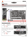
A1
A2
B C
D
E
F
G
H
I
J
K
L
M
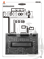
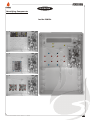
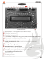
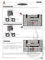
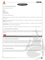
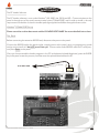
JUNIOR MAIN BOARD
N
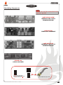
A Loop connections. A1 corresponds to Loop 1 and A2 to Loop 2
B Conventional sounder circuit 1
Conventional sounder circuit 2
5 pin connector for RS485, Fibre-optic or TCP/IP (LAN) connection with repeater panel
5 pin connector for multiplexed zone LEDs or relays
Auxiliary change-over relay output 1(Activated by any fire present on the system, disabled by front button)
Auxiliary change-over relay output 2
Fault NC relay contact
(Activated by any fire present on the system, disabled by front button)
(Activated by any fault present on the system, opens on fault)
Remote Evacuation or Class Change.
Remote disablement of selected detectors
9 way D-type connector for upload/download interface (LOADER software required)
24V auxiliary power supply output for powering external devices.
Max 300mA power limited and monitored
System power input
24V battery connection
INSTALLATION & COMMISSIONING MANUAL - REVISION 1.0 - 19.FEB.2007
18